
Bedienungsanleitung
Operation Manual
Innovation,
die bewegt!
6
DC
=
AC
~
5096
H0 Fußgängerampel, 4 Stück
H0 Pedestrian signal, 4 pieces
1.
Wichtige Hinweise / Important information
... 2
2. Einleitung / Introduction............................... 2
3. Einbau / Mounting ........................................ 3
4. Anschluss / Connection............................... 3
5. Betrieb / Operation ...................................... 4
6.
Fehlersuche und Abhilfe / Trouble-shooting...
5
7. Gewährleistung / Warranty.......................... 5
8. Technische Daten / Technical data.............. 5

2
DE EN
1. Wichtige Hinweise
Bitte lesen Sie vor der ersten Anwendung des Produktes
bzw. dessen Einbau diese Bedienungsanleitung auf-
merksam durch. Bewahren Sie diese auf, sie ist Teil des
Produktes.
1.1 Sicherheitshinweise
Vorsicht:
Verletzungsgefahr!
Aufgrund der detaillierten Abbildung des Originals bzw.
der vorgesehenen Verwendung kann das Produkt Spit-
zen, Kanten und abbruchgefährdete Teile aufweisen. Für
die Montage sind Werkzeuge nötig.
Stromschlaggefahr!
Die Anschlussdrähte niemals in eine Steckdose einfüh-
ren! Verwendetes Versorgungsgerät (Transformator,
Netzteil) regelmäßig auf Schäden überprüfen. Bei Schä-
den am Versorgungsgerät dieses keinesfalls benutzen!
Stromquellen unbedingt so absichern, dass es bei einem
Kurzschluss nicht zum Kabelbrand kommen kann.
1.2 Das Produkt richtig verwenden
Dieses Produkt ist bestimmt:
- Zum Einbau in Modelleisenbahnanlagen und Dioramen.
- Ausschließlich zum Anschluss an die Steuerelektronik
der Ampel Art. 5094/5095.
- Zum Betrieb in trockenen Räumen.
Jeder darüber hinausgehende Gebrauch gilt als nicht be-
stimmungsgemäß. Für daraus resultierende Schäden haftet
der Hersteller nicht.
1.3 Packungsinhalt überprüfen
Kontrollieren Sie den Lieferumfang auf Vollständigkeit:
- 4 Fußgängerampeln
- 4 Halteringe
- Anleitung
- Etikettenbogen
2. Einleitung
Fußgängerampeln im Stil der Epochen III – VI. Dieses
Set besteht aus 4 Fußgängerampeln mit je einer ro-
ten und grünen LED. Sie dienen zum Absichern von
Fußgängerüberwegen an Kreuzungen. Vorbildgetreuer
Messingmast mit Steckfuß für eine besonders einfache
Montage. Wartungsfrei dank LED-Beleuchtung. Die Fuß-
gängerampeln können nur in Verbindung mit der Am-
pel Art. 5094/5095 betrieben werden. Die Ansteuerung
erfolgt über die in Art. 5094/5095 enthaltene Elektronik.
Für eine Kreuzung (2 Straßen) werden 2x Art. 5094/5095
und 1x Art. 5096 benötigt.
1. Important information
Please read this manual completely and attentively before
using the product for the first time. Keep this manual. It is
part of the product.
1.1 Safety instructions
Caution:
Risk of injury!
Due to the detailed reproduction of the original and the
intended use, this product can have peaks, edges and
breakable parts. Tools are required for installation.
Electrical hazard!
Never put the connecting wires into a power socket!
Regularly examine the transformer for damage. In case
of any damage, do not use the transformer.
The power sources must be protected to avoid the risk
of burning cables.
1.2 Using the product for its correct purpose
This product is intended:
- For installation in model train layouts and dioramas.
- Only for connection to the electronic control module of
item 5094/5095
- For operation in dry rooms only.
Using the product for any other purpose is not approved
and is considered inappropriate. The manufacturer is not
responsible for any damage resulting from the improper
use of this product.
1.3 Checking the package contents
Check the contents of the package for completeness:
- 4 Pedestrian signals
- 4 Retaining rings
- Manual
- Decal
2. Introduction
Pedestrian signal for epochs III – VI. The set contains
4 pedestrian lights, with red and green LEDs, used for
pedestrian crosswalks. Prototypical brass mast with
base socket for easy mounting. Maintenance free by LED
lighting. The pedestrian signals are only usable with
traffic lights item 5094/5095, which contains the nec-
essary electronic control module. For a full two-street
intersection 2 x item 5094/5095 and 1 x item 5096 are
required.

3
3. Einbau
Achtung:
Artikel enthält abbruchgefährdete Kleinteile, Ampel beim
Einstecken nur am unteren Teil des Mastes anfassen. Mast
und Steckfuß sind nicht fest miteinander verbunden.
Abb. 1 Abb. 2
Ø 4 mm
Fig. 1 Fig. 2
3. Mounting
Please note:
Item contains breakable parts. When inserting, touch the
traffic light only at the lower part of the mast. Mast and
base socket are not tightly connected.
Mount the traffic lights as described below:
1. Drill a 4 mm hole at the appropriate position on your
layout (see fig. 1).
2. First insert the base with the wire leads into the hole
(see fig. 2).
3. Insert the mast of the traffic lights into the base, which
causes the latter to be firmly fastened in the hole. In
case the base does not fit firmly in the hole, slide the
retaining ring onto the base from below.
4. Make sure there is a short loop (about 2 – 3 cm) below
the base to enable you to remove the mast from the
base and put it sideways on the layout, should this
become necessary for maintenance reasons.
Attention: Do not exert any undue force to the very thin
wires from the mast to the connecting points of the wiring
leads. Carefully bend the wires preferably only once in
order to avoid any wire breakage.
4. Connection
Caution:
Resistors at the cables are needed for proper function of
the lamp. Never cut them off! Never cover resistors with
insulation material, because they have to be cooled by
surrounding air!
Connect the pedestrian signal to the electronic control
modules of item 5094/5095 (2x) as shown in fig. 3. Con-
nect the electronic control modules as described in the
manual of item 5094/5095 to a transformer, e. g. Viess-
mann item 5200. Finally connect the blue cable of the
second electronics to the blue input of the first electronics.
Montieren Sie die Ampel wie folgt:
1. Bohren Sie an der Montagestelle ein Loch mit einem
Durchmesser von 4 mm (Abb. 1).
2. Stecken Sie zuerst den Steckfuß mit den Anschlusska-
beln durch die Bohrung (Abb. 2).
3. Stecken Sie den Mast der Ampel in den Steckfuß,
wodurch dieser in der Bohrung festklemmt. Falls der
Steckfuß nicht genügend Halt findet, schieben Sie den
Haltering von unten auf den Steckfuß.
4. Lassen Sie beim Anschließen der Kabel unterhalb der
Ampel eine Schleife von ca. 2 – 3 cm Länge, damit Sie
die Ampel bei eventuellen Arbeiten aus der Montage-
bohrung ziehen können.
Achtung: Wegen der sehr dünnen Drähte zwischen dem
Ampelmast und den Verbindungsstellen zu den Anschluss-
litzen darf auf keinen Fall Zug auf die Anschlussleitungen
ausgeübt werden. Das Umbiegen der Drähte muss vor-
sichtig geschehen und sollte nicht mehrfach erfolgen, um
Drahtbruch zu vermeiden.
4. Anschluss
Vorsicht:
Widerstände an den Enden der Anschlussdrähte sind für
die Funktion erforderlich. Keinesfalls entfernen! Wider-
stände nicht mit Isolationsmaterial umhüllen, da sonst
keine ausreichende Kühlung möglich ist!
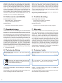
Schließen Sie die Fußgängerampeln wie in Abb. 3 gezeigt
an die Steuerelektroniken von Art. 5094/5095 (2x) an.
Schließen Sie die Steuerelektroniken wie in der Anleitung
von Art. 5094/5095 beschrieben an einen Transformator
an, z. B. Viessmann Art. 5200. Das blaue Kabel der zwei-
ten Elektronik verbinden Sie mit dem blauen Eingang der
ersten Elektronik.

4
Sekundär
0-10-16 V~
16 V
Primär
230 V~
Gefertigt nach
VDE 0570
EN 61558
Lichttransformator
5200
Nur für trockene Räume
Primär 230 V 50 - 60 Hz
Sekundär max. 3,25 A52 VA
ta 25°CIP 40
10 V
0 V
5. Betrieb
Die unterschiedlichen Betriebsarten entnehmen Sie der
Anleitung zu Art. 5094/5095.
Für die Schaltungen der verschiedenen Betriebsarten be-
nötigen Sie nur die Kabel der ersten Elektronik. Die Kabel
der zweiten Elektronik bleiben dabei stets wie in Abb. 3
gezeigt mit der ersten Elektronik verbunden.
5. Betrieb
You will find the different operating modes in the instruc-
tions of item 5094/5095.
For the circuits of the different operating modes you only
need the cables of the first electronics. The cables of the
second electronics remain connected to the first electron-
ics as shown in fig. 3.
Abb. 3 Fig. 3
z. B. / e. g.
5200
1
1
1
1
22
2
2
2
1
z. B. / e. g.
48261
blau / blue
blau / blue
gelb / yellow
braun / brown
rot / red
gelb /
yellow
grün / green
Eine Marke von Viessmann

5
Hinweis: Falls Sie einen Art. 5095 der ersten Generation
besitzen, unterscheiden sich die Etiketten der Steuerelek-
tronik von den in dieser Anleitung gezeigten. In diesem Fall
kleben Sie die beiliegenden Etiketten auf die Steuerelek-
tronik. Dort sind die Eingänge für die Fußgängerampeln
markiert. Das Etikett mit dem blauen Dreieck kleben Sie
über das alte Etikett mit dem blauen Kreis, das Etikett mit
dem schwarzen Kreis entsprechend über die andere Seite.
Technisch unterscheiden sich die Elektroniken nicht, es
handelt sich nur um erweiterte Markierungen.
6. Fehlersuche und Abhilfe
Ampel funktioniert nicht
- Steuerkabel nicht angeschlossen?
- Polung bei DC-Betrieb falsch?
Abläufe falsch
- Anschlüsse der Ampel falsch gesteckt?
7. Gewährleistung
Jeder Artikel wurde vor Auslieferung auf volle Funktionalität
geprüft. Der Gewährleistungszeitraum beträgt 2 Jahre ab
Kaufdatum. Tritt in dieser Zeit ein Fehler auf und Sie finden
die Fehlerursache nicht, nehmen Sie bitte Kontakt mit uns
auf ([email protected]).Senden Sie uns
den Artikel zur Kontrolle bzw. Reparatur bitte erst nach
Rücksprache zu. Wird nach Überprüfung des Artikels ein
Herstell- oder Materialfehler festgestellt, wird er kostenlos
instandgesetzt oder ausgetauscht. Von der Gewährleistung
und Haftung ausgeschlossen sind Beschädigungen des
Artikels sowie Folgeschäden, die durch unsachgemäße
Behandlung, Nichtbeachten der Bedienungsanleitung, nicht
bestimmungsgemäßen Gebrauch, eigenmächtigen Eingriff,
bauliche Veränderungen, Gewalteinwirkung, Überhitzung
u. ä. verursacht werden.
8. Technische Daten
Ausschließlich zum Anschluss an die Steuerelektronik
von Art. 5094/5095.
Höhe: 4,1 cm
Hint: If you have an item 5095 of the first generation, the
decal of the electronic control module is different to the
decal shown in this manual. In this case glue the attached
decals to the control module. The inputs for the pedestrian
signals are marked. Stick the decals with the blue triangle
over the decal with the blue circle, the decal with the black
circle across the other side.
Technically, the electronics do not have any differences,
they are only extended markings.
6. Trouble-shooting
Traffic light does not work
- Control wire not properly connected
?
- Wrong polarity in DC mode?
Wrong sequences
- Connections to the traffic lights wrongly plugged?
7. Warranty
Each model is tested as to its full functionality prior to de-
livery. The warranty period is 2 years starting on the date
of purchase. Should a fault occur during this period please
contact our service department (service@viessmann-
modell.com). Please send the item to the Viessmann ser-
vice department for check and repair only after consulta-
tion. If we find a material or production fault to be the cause
of the failure the item will be repaired free of charge or
replaced. Expressively excluded from any warranty claims
and liability are damages of the item and consequential
damages due to inappropriate handling, disregarding the
instructions of this manual, inappropriate use of the model,
unauthorized disassembling, construction modifications
and use of force, overheating and similar.
8. Technical data
Only for connection to the electronic control module of
item 5094/5095.
Height: 4.1 cm
Änderungen vorbehalten. Keine Haftung für Druckfehler
und Irrtümer.
Die aktuelle Version der Anleitung finden Sie auf der Viess-
mann Homepage unter der Artikelnummer.
Subject to change without prior notice. No liability for
mistakes and printing errors.
You will find the latest version of the manual on the Viess-
mann website using the item number.
Entsorgen Sie dieses Produkt nicht über den
(unsortierten) Hausmüll, sondern führen Sie
es der Wiederverwertung zu.
Do not dispose of this product through (unsorted)
domestic waste, supply it to recycling instead.

Modellbauartikel, kein Spielzeug! Nicht geeignet für
Kinder unter 14 Jahren! Anleitung aufbewahren!
Model building item, not a toy! Not suitable for children
under the age of 14 years! Keep these instructions!
Ce n’est pas un jouet! Ne convient pas aux enfants de moi-
ns de 14 ans! Conservez cette notice d’instructions!
Não é um brinquedo! Não aconselhável para menores de
14 anos! Conservar o manual de instruções!
Modelbouwartikel, geen speelgoed! Niet geschikt voor
kinderen onder 14 jaar! Gebruiksaanwijzing bewaren!
Articolo di modellismo, non è un giocattolo! Non adatto
a bambini al di sotto dei 14 anni! Conservare istruzioni per
l’uso!
Artículo para modelismo ¡No es un juguete! No
recomendado para menores de 14 años! Conserva las
instrucciones de servicio!
DE
EN
FR
NL
IT
ES
PT
Made in Europe
Viessmann
Modelltec
hnik GmbH
Bahnhofstraße 2a
D - 35116 Hatzfeld-Reddighausen
+49 6452 9340-0
www.viessmann-modell.de
6
96345
Stand 03/fa
11/2021
Ho/Kf
Notizen Notes
-
 1
1
-
 2
2
-
 3
3
-
 4
4
-
 5
5
-
 6
6


