Bresser 7000026000000 Bedienungsanleitung
- Kategorie
- Wecker
- Typ
- Bedienungsanleitung

Weather Station · Wetterstation ·
Thermo Hygro Quadro Neo C
EN Instruction manual
DE Bedienungsanleitung

DE
Besuchen Sie unsere Website über den folgenden QR Code oder Weblink um weitere Informationen
zu diesem Produkt oder die verfügbaren Übersetzungen dieser Anleitung zu finden.
EN
Visit our website via the following QR Code or web link to find further information on this product or
the available translations of these instructions.
FR
Si vous souhaitez obtenir plus d’informations concernant ce produit ou rechercher ce mode d’emploi en
d’autres langues, rendez-vous sur notre site Internet en utilisant le code QR ou le lien correspondant.
NL
Bezoek onze internetpagina via de volgende QR-code of weblink, voor meer informatie over dit
product of de beschikbare vertalingen van deze gebruiksaanwijzing.
ES
¿Desearía recibir unas instrucciones de uso completas sobre este producto en un idioma determinado?
Entonces visite nuestra página web utilizando el siguiente enlace (código QR) para ver las versiones
disponibles.
IT
Desidera ricevere informazioni esaustive su questo prodotto in una lingua specifica? Venga a visitare
il nostro sito Web al seguente link (codice QR Code) per conoscere le versioni disponibili.
www.bresser.de/P7000026000000
www.bresser.de/warranty_terms
GARANTIE · WARRANTY · GARANTÍA · GARANZIA
RECYCLAGE (TRIMAN/FRANCE)


4 / 44
1 Imprint
Bresser GmbH
Gutenbergstr. 2
46414 Rhede
Germany
www.bresser.de
For any warranty claims or service inquiries, please refer to
the information on "Warranty" and "Service" in this docu-
mentation. We ask for your understanding that unsolicited
returns cannot be processed.
Errors and technical changes excepted.
© 2023 Bresser GmbH
All rights reserved.
The reproduction of this documentation - even in extracts -
in any form (e.g. photocopy, print, etc.) as well as the use
and distribution by means of electronic systems (e.g. image
file, website, etc.) without the prior written permission of
the manufacturer is prohibited.
The designations and brand names of the respective com-
panies used in this documentation are generally protected
by trade, trademark and/or patent law in Germany, the
European Union and/or other countries.
2 Validity note
This documentation is valid for the products with the follow-
ing article numbers:
7000026000000
Manual version: 0823
Manual designation:
Manual_7000026000000_Thermo-Hygro-Quadro-Neo-C_en-
de_BRESSER_v082023a
Always provide information when requesting service.

5 / 44
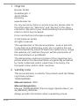
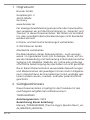
3 About this Instruction Manual
NOTICE
These operating instructions are to be considered a
component of the device.
Read the safety instructions and the instruction manual
carefully before using this device.
Keep these instruction manual in a safe place for future ref-
erence. If the device is sold or passed on, the instruction
manual must be passed on to any subsequent owner/user
of the product.

6 / 44
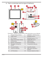
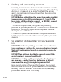
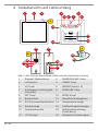
4 Parts overview and scope of delivery
CH1
CH
3 2 1
°C/°F
AAA/LR03
AAA/LR03
+
+
12
20
19
15
4
6
5
8
9
11
7
16
14
17
21
18
12
B
3
A
13
22
23
C
10
Illustration1: All parts of base station (top) and wireless sensor (bottom)
1 Display* (base station) 2 [SNOOZE / LIGHT] button
3 Light sensor 4 [DOWN] buttons
5 [UP ] button 6 [ROOM] buttons (1-3)
7 Wall mount (base station) 8 PRESSURE button
9 [SET] button 10 [RESET] knob
11 Battery compartment 12 Stand (foldable)
13 DC power connection
socket
14 Temperature display
15 Channel display 16 Humidity display
17 Function indicator 18 Wall mount (wireless
sensor)
19 [°C/°F] button 20 Channel selection slider

7 / 44
21 Battery compartment (wire-
less sensor)
22 Mains plug
23 DC barrel connector *For more information, see the
chapter "Display ads"
Delivery content Base station (A), wireless sensor (3 pcs.)
(B), power adapter (C)
Also required (not included):
9 pcs. Mignon batteries (1.5V, type AAA/LR03), small Phillips
screwdriver
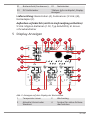
5 Screen display
13
26
2
5
6
4
7
8
9
10
12
13
14
15
16
17
19
18
22
23
24
11
25
21
20
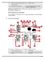
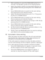
Illustration2: Indications on the display of the base station
1 Indoor temperature 2 Weekday
3 Current time or alarm
time
4 Symbol for active snooze
function

8 / 44
5 Symbol for enabled alarm 6 Symbol for active time zone
setting
7 Radio clock signal recep-
tion icon
8 Symbol for active daylight
saving time
9 History of hours 10 Barometric pressure
11 AM/PM display in 12-hour
mode
12 Current date
13 Weather trend graphic 14 Outdoor temperature
(wireless sensor)
15 Outdoor humidity (wire-
less sensor)
16 Room description (for
sensor location)
17 Climate Indicator 18 Symbol for MAX or MIN
value info
19 Battery status (wireless
sensor)
20 Trend arrows
21 Symbol for connection to
the wireless sensor
22 Channel of the radio sensor
23 Symbol for cold forecast /
cold warning
24 Indoor humidity (in %)
25 Battery status (base sta-
tion)
26 Symbol for the indoor dis-
play
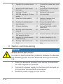
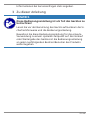
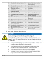
6 Before commissioning
NOTICE
Avoid connection faults!
In order to avoid connection problems between the devices,
the following points must be observed during commission-
ing.
1. Place the base unit (receiver) and sensor (transmitter)
as close together as possible.
2. Connect the power supply to the base unit and wait un-
til the indoor temperature is displayed.
3. Establish power supply for the sensor.

9 / 44
4. Set up/operate the base unit and sensor within the ef-
fective transmission range.
5. Make sure that the base unit and the radio sensor are
set to the same channel.
When changing the batteries, always remove the batteries
from both the base unit and the sensor and reinsert them in
the correct order so that the radio link can be re-estab-
lished. If one of the two devices is operated via a mains
power connection, the power connection must also be
briefly disconnected for this device when the batteries are
changed. If, for example, only the batteries in the sensor
are replaced, the signal may subsequently not be received
at all or not be received correctly.
Note that the actual range depends on the respective con-
struction materials used for the buildings as well as the re-
spective position of the base unit and the outdoor sensor.
External influences (various radio transmitters and other
sources of interference) can greatly reduce the possible
range. In such cases, we recommend finding other locations
for both the base unit and the outdoor sensor. Sometimes
moving the sensor by just a few centimeters is enough!
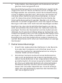
7 Battery level indicator
1. When the level of the batteries in the base station or in
the wireless sensor reaches a critical level, the battery
level symbol appears in the appropriate area on the
display.
2. When replacing one set of batteries, always remove the
batteries from the other part of the unit and reinsert
them in the correct order (see chapter "Setting up
power supply"). Replace the batteries to be changed in
the corresponding part of the device with a completely
new set with full capacity. This ensures that the connec-
tion between the devices will be reestablished again
correctly.

10 / 44
8 Finding and connecting a sensor
Normally, the connection between the base station and the
sensor is established automatically. However, after a battery
change or in the event of a connection fault, the sensor
search can be triggered manually and thus the connection
re-established.
NOTICE!Before establishing the connection, make sure that
the sensors are set to different channels (1, 2 and 3). The
base station will then display channel 1 as ROOM1, channel
2 as ROOM2 and channel 3 as ROOM3.
1. In normal display mode, long press the [ROOM1],
[ROOM2] or [ROOM3] button for 2-3 seconds to activate the
reception of the sensor signal for the displayed channel.
The signal icon will flash.
2. The signal symbol flashes until the reception is success-
ful. If no signal is received within 5 minutes, the symbol dis-
appears.
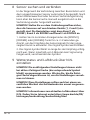
9 Set weather status and air pressure above
n.n.
NOTICE!The following settings cannot be made when the
time signal search is active (the corresponding icon flashes).
Wait until the time signal search is completed to make the
settings.
NOTICE!These settings should also be made again if the
device location is changed significantly.
NOTICE!Information on the current value for the air pres-
sure above n.n. can be found on the Internet at https://
www.radar-live.com/p/atmospheric-pressure.html
For a correct display of the weather forecast, the current
weather status and the air pressure above n.n. must be set
correctly. The first weather forecast will be displayed ap-
proximately 6 hours after the set-up.

11 / 44
1. After switching on, press the PRESSURE button for 3
seconds. The weather symbol on the display flashes.
2. Select the graphic symbol corresponding with the cur-
rent weather status by pressing the UP or DOWN but-
ton.
3. Press PRESSURE button to switch to the next setting.
The temperature unit indicators flash.
4. Select the desired temperature unit (°C or °F) by press-
ing the UP or DOWN button.
5. Press PRESSURE button to switch to the next setting.
The air pressure unit indicator flashes.
6. Select the desired air pressure unit (inHg or mbh Pa) by
pressing the UP or DOWN button.
7. Press PRESSURE button to switch to the next setting.
The air pressure value indicator flashes.
8. Set the current value for the air pressure above n.n. by
pressing the UP or DOWNbutton.
9. Finally, press the PRESSURE button to save the settings
and return to the normal display mode.
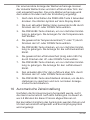
10 Automatic time setting
After the power has been restored, the unit automatically
searches for the radio signal. It takes approximately 3-8
minutes for this process to be completed.
If the radio signal is received correctly, the date and time
are set automatically and the reception symbol is displayed.
If no radio signal has been received, proceed as follows:
1. Press the DOWN button for approx. 2 seconds to initi-
ate the reception of the radio signal again.
2. Press the DOWN button once again for approx. 2
seconds to stop the reception of the radio signal.

12 / 44
3. If still no radio signal is received, the time must be set
manually.
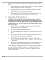
11 Manual time setting
NOTICE!A manual time setting cannot be made when the
time signal search is active (the corresponding symbol
flashes). Wait until the time signal search is completed to
make the manual time setting.
1. Press the SET button for approx. 3 seconds to enter the
time setting mode.
2. Digits to be set are flashing.
3. Press UP or DOWN button to change the value.
4. Press the SET button to confirm and switch to the next
setting.
5. Settings sequence: Hours > Minutes > 12/24 hour mode
> Year > Month > Day > Time zone > Language
6. Finally, press the SET button to save the settings and
exit settings mode.
*The language setting refers to the days of the week as well
as to the room names. Available languages: English, Ger-
man, French, Spanish, Italian, Danish, Swedish
12 Time zone setting
The time zone is set as part of the manual time setting. You
can also find more detailed information in the chapter
"Manual time setting".
1. Press the SET button for approx. 3 seconds to enter the
time setting mode.
2. Press the SET button several times until the display
shows the setting for the time offset (the factory setting
is '00').
3. Press UP or DOWN button to select the desired time de-
viation in hours (-23 up to +23 hours).

13 / 44
4. Press the SET button for approx. 3 seconds to confirm
the selected time deviation.
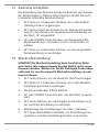
13 Alarm setting
NOTICE!The alarm setting cannot be made when the time
signal search is active (the corresponding symbol flashes).
Wait until the time signal search is completed to set the
manual alarm.
1. Press the SET button to display the alarm time (ALM).
2. Press the SET button for about 3 seconds to enter the
alarm time settings mode.
3. Digits to be set are flashing.
4. Press UP or DOWN button to change the value.
5. Press the SET button to confirm and switch to the next
setting.
6. Settings sequence: Hours > Minutes
7. Finally, press the SET button to save the settings and
exit settings mode.
Enable/disable the alarm
8. In normal display mode, press the SET button to display
the currently set alarm time. The alarm time and the
alarm status (ALM/OFF) are displayed.
9. Press the UP or DOWN button to enable the alarm
(ALM). The symbol is displayed on the LCD.
10. Press the UP or DOWN button to disable the alarm. The
symbol is no longer displayed.

14 / 44
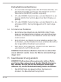
14 Snooze function
1. When the alarm tone sounds, press the SNOOZE/LIGHT
button on the top of the base station to activate the
snooze function. The alarm sounds again after 5
minutes.
2. When the alarm sounds, press any other button to stop
the alarm until the set alarm time is reached again.
3. If no button is pressed, the alarm is automatically
switched off after 2 minutes.
NOTICE!The snooze function can be reactivated up to seven
times before the alarm is automatically stopped.
15 Change room name
NOTICE!The room name cannot be changed when the time
signal search is active (the corresponding icon flashes). Wait
until the time signal search is completed to be able to
change the room name.
1. Press the ROOM button of the desired wireless sensor.
The room name flashes.
2. Press the ROOM button repeatedly to select one of the
5 preset room names. Alternatively, continue with 3. or
wait approx. 5 seconds until the change has been saved
automatically. The display stops flashing.
3. Press the UP button to switch to the entry of a free
room designation. "_" flashes.
4. Press the UP button until the desired input value
flashes. Possible input values: A-Z, 0-9, _ > < / * -
5. Press the ROOM button again to switch to the next in-
put value and enter it as described under 4.
6. Finally, press the ROOM button to save the entry. If no
entry is made within 5 seconds, the settings made up to
this point are automatically saved. In both cases the
display stops flashing and the free input is stored.

15 / 44
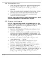
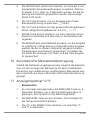
16 Receiving measurements automatically
Once batteries are installed, the base station will display the
measurement readings. Readings from the remote sensor
will be displayed within 3 minutes after powering it on.
17 Display change °C/°F
•Base station
1. In normal display mode, press the PRESSURE button for
about 3 seconds to enter the settings mode. The sym-
bol for the weather situation flashes.
2. Press the PRESSURE button again. The temperature
unit indicators flash.
3. Press the UP or DOWN button to toggle between °C
and °F.
4. To automatically save the setting made, do not make
any further adjustments for about 5 seconds. The base
station automatically switches back to normal display
mode. Alternatively, press the PRESSURE button several
times until the display stops flashing.
•Wireless sensor
Open the battery compartment.
Press the °C/°F button to toggle between °C and °F.
Close the battery compartment again.
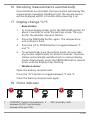
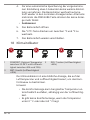
18 Clima indicator
123
1 COMFORT: Optimal (Temperature
between 20-28°C and humidity
between 40% and 70%)
2 DRY: Humidity >65%

16 / 44
3 WET: Humidity <45%
The clima indicator is a pictorial indication based on air tem-
perature and humidity in an attempt to determine comfort
level.
Note:
• Comfort indication can vary under the same temperat-
ure, depending on the humidity.
• There is no comfort indication when temperature is be-
low 0° C (32° F) or over 60° C (140° F)
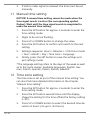
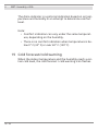
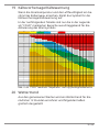
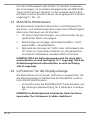
19 Cold forecast/cold warning
When the indoor temperature and the humidity reach a cer-
tain cold level, the cold forecast / cold warning icon flashes.

17 / 44
In the following table, only the areas marked as "COLD" in
the legend are decisive for the activation of the warning
icon.
Cold
Temperature/Humidity 20 22 24 26 27 28 29 30 31 33 35 37 38 40 42 45 47 49 53 55 57 60 63 65 70 73 75 77 79 80 82 85 88 91 95 99
42
41
40
39
38
37
36
35
34
33
32
31
30
29
28
27
26
25
24
23
22
21
20
19
18
17
16
15
14
13
12
11
10
9
8
7
6
5
4
3
2
1
0
Flue Alert Safe Heatstroke Alert Heatstroke Warning Danger
Illustration3: Temperature and humidity areas marked as "COLD".
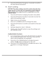
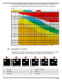
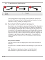
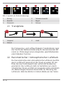
20 Weather Trend
A weather trend for the next 12 hours is calculated from the
measured values and displayed graphically as follows:
123456
Illustration4: Symbols of the weather trend display
1 Sunny 2 Partly Cloudy
3 Cloudy 4 Rainy
5 Stormy 6 Snowy

18 / 44
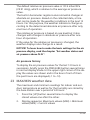
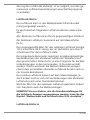
21 Trend arrow indicators
123
1 Rising 2 Steady
3 Falling
The temperature and humidity trend indicator shows the
trends of changes in the forthcoming few minutes. Arrows
indicate a rising, steady or falling trend.
22 Barometric/Atmospheric pressure
Barometric or atmospheric pressure (hereinafter referred to
as "air pressure") is the pressure at any place on earth due
to the weight of the layer of air above it. The air pressure is
in relation to the average pressure and gradually decreases
with increasing altitude. Meteorologists use barometers to
measure the air pressure. Because the weather depends on
changes in air pressure to a large extent, it is possible to
make a weather forecast from the measured air pressure
changes.
Air pressure values
The air pressure can be displayed in the units hPa/mba or
mmHg.
A distinction is made between the following air pressure val-
ues:
Abs: Absolute air pressure at your current location
Rel: Relative air pressure based on sea level (N.N.)

19 / 44
The default relative air pressure value is 1013 mbar/hPa
(29.91 inHg), which is relative to the average air pressure
value.
The built-in barometer registers environmental changes in
absolute air pressure. Based on the collected data, a fore-
cast can be made for the weather conditions in the next 12
hours. For this purpose, the weather indicators change ac-
cording to the determined absolute air pressure after only
one hour of operation.
The relative air pressure is based on sea level but it also
changes with changes in absolute air pressure after one
hour of operation.
If the value for the relative air pressure is changed, the
weather displays also change as a result.
NOTICE!To learn how to make the basic settings for the air
pressure display, read the chapter "Set weather status and
air pressure above N.N.".
Air pressure history
To display the air pressure values for the last 12 hours in
succession, briefly press the PRESSURE button several times
in normal display mode. In the upper right corner of the dis-
play the values are shown and in the box in front of them
the past hours are displayed (-1 to -12).
23 MAX/MIN weather data
The maximum and minimum readings for indoor and out-
door temperature as well as for the humidity are stored by
the base station over a period of 24 hours:
1. Press the [UP] button several times to display the
stored values one after the other.
2. Display sequence: Maximum values (MAX) > Minimum
values (MIN) > Current values

20 / 44
3. While the minimum or maximum values are displayed,
press the [UP] button for approx. 3 seconds to irrevoc-
ably delete the stored maximum/minimum values.
NOTICE!If the recording range for a value is undershot,
'LL.L' is shown in the display. If the recording range is ex-
ceeded, 'HH.H' is shown in the display.
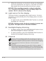
24 Light sensor for the display
The base station is equipped with a light sensor. In mains
operation, it automatically dims the display when it is dark
(night mode).
• In night mode, press SNOOZE/LIGHT button to activate
backlight for 5 seconds.
NOTICE!In battery mode, the device operates in power sav-
ing mode. The light sensor is therefore disabled.
25 Backlight/Display dimming
1. In battery mode, press the SNOOZE/LIGHT button to en-
able the backlight for about 5 seconds.
2. In mains operation, press the SNOOZE/LIGHT button to
disable the backlight (display dimming).
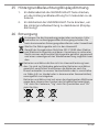
26 Disposal
Dispose of the packaging materials according to its type. In-
formation on proper disposal can be obtained from the muni-
cipal waste disposal service provider or environmental agency.
Do not dispose of electronic devices in the household
garbage!
According to the European Directive 2012/19/EU on Waste
Electrical and Electronic Equipment and its transposition into
national law, used electrical equipment must be collected sep-
arately and recycled in an environmentally sound manner.
Seite laden ...
Seite laden ...
Seite laden ...
Seite laden ...
Seite laden ...
Seite laden ...
Seite laden ...
Seite laden ...
Seite laden ...
Seite laden ...
Seite laden ...
Seite laden ...
Seite laden ...
Seite laden ...
Seite laden ...
Seite laden ...
Seite laden ...
Seite laden ...
Seite laden ...
Seite laden ...
Seite laden ...
Seite laden ...
Seite laden ...
Seite laden ...
-
 1
1
-
 2
2
-
 3
3
-
 4
4
-
 5
5
-
 6
6
-
 7
7
-
 8
8
-
 9
9
-
 10
10
-
 11
11
-
 12
12
-
 13
13
-
 14
14
-
 15
15
-
 16
16
-
 17
17
-
 18
18
-
 19
19
-
 20
20
-
 21
21
-
 22
22
-
 23
23
-
 24
24
-
 25
25
-
 26
26
-
 27
27
-
 28
28
-
 29
29
-
 30
30
-
 31
31
-
 32
32
-
 33
33
-
 34
34
-
 35
35
-
 36
36
-
 37
37
-
 38
38
-
 39
39
-
 40
40
-
 41
41
-
 42
42
-
 43
43
-
 44
44


Bresser 7000026000000 Bedienungsanleitung
- Kategorie
- Wecker
- Typ
- Bedienungsanleitung
in anderen Sprachen
- English: Bresser 7000026000000 Owner's manual
Verwandte Papiere
-
Bresser 7902585 Bedienungsanleitung
-
Bresser 7902580 Bedienungsanleitung
-
-
-
-
Bresser 9080500 - Colour Weather Center 5-in-1 National Geographic Bedienungsanleitung
-
-
-