Cal Spas Portable Spas Bedienungsanleitung
- Typ
- Bedienungsanleitung


LTR20121001, Rev. A
12/30/11

Important Safety Instructions
Basic Spa Information..................1
Preparing for Your New Portable Spa
Planning the Best Location ..............3
Preparing a Good Foundation ............3
230 Volt Electrical Installation ...........4
RCD Wiring Diagram ...................6
6115 and 6215 Circuit Board Connection ..7
8015 Circuit Board Connection...........8
OE9905 P4 Circuit Board Connection ......9
Electrical Installation for 8.5 kW Heater . .10
Filling and Powering Up Your Portable Spa 11
Operating Your Spa
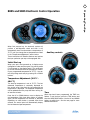
6105 and 6205 Electronic Control Operation 1 2
8005 and 9005 Electronic Control Operation 1 5
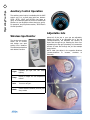
Auxiliary Control Operation ............20
Wireless Spa Monitor .................20
Adjustable Jets ......................20
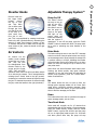
Diverter Knobs.......................21
Air Venturis .........................21
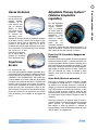
Adjustable Therapy System™ ...........21
Multi-Colored Spa Light Operation.......22
Waterfalls ..........................22
Water Quality Maintenance
Clear Water Plan .....................23
Before You Begin.....................23
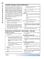
Chemical Safety......................24
Chemical Descriptions.................25
Traditional Chemical Start Up...........26
Bromine Clear Water Plan..............26
Chlorine Clear Water Plan..............27
Ozonator Clear Water Plan .............27
Cal Clarity II Bromine Generator ........28
Maintenance Schedule ................30
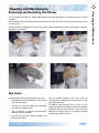
Cleaning and Maintenance
Removing and Reseating the Pillows.....31
Spa Cover...........................31
Draining Your Portable Spa ............32
Winterizing (Cold Climate Draining) .....33
Cleaning the Cover, Shell and Pillows ....33
Cleaning and Replacing the Filter........35
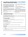
Using the Entertainment System
Operating the CD Player . . . . . . . . . . . . . . . 36
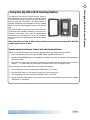
Using the AQ-DM-4 iPod Docking Station .37
Keeping Fit With Your Swim Spa
Using the Exercise Equipment ..........38
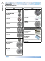
Appendix
Replacement Parts ...................40
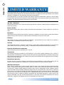
Limited Warranty.....................46
Copyright 2011-2012 Lloyd’s Material Supply, Inc. All rights reserved. Duplication without written
consent is strictly prohibited.
Cal Spas™, Adjustable Therapy System™, ATS™, Cal Premium™, Cal Select™, Cal Stone™,
Ultimate Fitness Spa Series™, and XL Heat Exchanger™ are registered trademarks.
Due to continuous improvement programs, all models, operation, and/or specications are
subject to change without prior notice.
LTR20121001, Rev. A
12/30/11
100-1072
CONTACT INFORMATION
For customer service, please contact
your authorized dealer immediately. If
you need additional information and/
or assistance, please contact:
LMS Customer Service Department
1462 East Ninth Street
Pomona, CA 91766.
Phone: 1-909-623-8781
Fax: 1-909-629-3890

2012 Portable Spa
LTR20121001, Rev. A
Read This First!
www. ca l s p a s . c o m
1
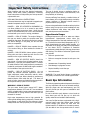
When installing and using this electrical equipment,
always follow basic safety precautions. Following
these instructions will help make your rst spa session
a pleasurable one.
READ AND FOLLOW ALL INSTRUCTIONS
A licensed electrician may be required to upgrade your
standard receptacle and/or circuit breaker.
DANGER -- RISK OF ACCIDENTAL DROWNING: Do
not allow children to be in or around a spa unless
a responsible adult supervises them. Keep the spa
cover on and locked when not in use. See instructions
enclosed with your cover for locking procedures.
DANGER -- RISK OF INJURY: The suction ttings in
this spa are sized to match the specic water ow
created by the pump. Should the need arise to replace
the suction ttings, or the pump, be sure the ow
rates are compatible.
DANGER -- RISK OF INJURY: Never operate the spa
if the suction tting or lter baskets are broken or
missing.
DANGER -- RISK OF INJURY: Never replace a suction
tting with one that is rated less than the ow rate
marked on the original suction tting.
DANGER -- RISK OF ELECTRIC SHOCK: Install the
spa at least 1.5 meters from all metal surfaces. As an
alternative, a spa may be installed within 1.5 meters
of metal surfaces if each metal surface is permanently
bonded by a minimum #8 AWG solid copper conductor
to the outside of the spa’s control box.
DANGER -- RISK OF ELECTRIC SHOCK: Do not
permit any external electrical appliances, such as
lights, telephones, radios, televisions, and etc., within
1.5 meters of the spa. Never attempt to operate any
electrical device from inside the spa. This does not
apply to lights, stereos and televisions that are built in
to the spa as factory options from Cal Spas™.
WARNING – RISK OF INJURY
The spa water should never exceed 40˚C. Water
temperatures between 38˚C and 40˚C are considered
safe for a healthy adult. Lower water temperatures are
recommended for young children and when spa use
exceeds 10 minutes.
High water temperatures have a high potential for
causing fetal damage during pregnancy. Women who
are pregnant, or who think they are pregnant, should
always check with their physician prior to spa usage.
The use of alcohol, drugs or medication before or
during spa use may lead to unconsciousness, with
the possibility of drowning.
Persons suffering from obesity, a medical history of
heart disease, low or high blood pressure, circulatory
system problems or diabetes should consult a
physician before using the spa.
Persons using medications should consult a physician
before using the spa since some medications may
induce drowsiness while others may affect heart
rate, blood pressure and circulation.
Hyperthermia Danger
Prolonged exposure to hot air or water can induce
hyperthermia. Hyperthermia occurs when the
internal temperature of the body reaches a level 2˚C
to 4˚C above the normal body temperature of 37˚C.
While hyperthermia has many health benets, it is
important not to allow your body’s core temperature
to rise above 39.5˚C. Symptoms of excessive
hyperthermia include dizziness, lethargy, drowsiness
and fainting. The effects of excessive hyperthermia
may include:
Failure to perceive heat•
Failure to recognize the need to exit spa or hot •
tub
Unawareness of impending hazard•
Fetal damage in pregnant women•
Physical inability to exit the spa•
Unconsciousness•
WARNING: The use of alcohol, drugs, or medication
can greatly increase the risk of fatal hyperthermia.
Basic Spa Information
The following operating and maintenance instructions
are very important and must be followed carefully.
With the proper care and maintenance, your Cal
Spa will provide you with years of satisfaction and
performance.
Do not be afraid to push buttons or turn knobs to
learn about your new Cal Spa, as it is built with
quality materials and excellent craftsmanship.
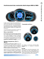
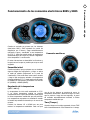
Your new Cal Spa has been engineered with a high-
powered water pump that pushes water through
various therapy jets, which will relax even the
tightest muscles. In addition to the water pressure,
you can add air into the spa water with air venturi
Important Safety Instructions

2012 Portable Spa
LTR20121001, Rev. A
Read This First!
www. c a l s p a s. c o m
2
handles located seat-side that increase the intensity of
your massage.
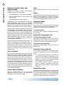
The ltering of this spa is very important. It will
minimize cleaning time and the amount of chemicals
needed to keep your spa water balanced. The two daily
pre-programmed lter cycles of two hours in duration
can be increased to six hour cycles if the need arises.
This can be accomplished through the topside control
panel.
IMPORTANT: Keep the spa covered when not in use!
Covered spas use less electricity while maintaining •
a set temperature.
Covering your spa will protect your spa’s nish •
from the sun’s ultraviolet rays.
You are required to keep the spa covered to •
maintain warranty coverage.
Covering your spa helps prevent children from •
drowning in the spa.
Your new Cal Spa comes equipped with an electric
heater. Following the directions listed below will ensure
the most efcient operation:
NOTE: This method is only for spa usage under two
hours a week.
Keep the spa’s operating temperature 3˚C below •
the desired usage temperature when not in use.
One or two hours before use, set the temperature
to the desired temperature.
If the spa usage exceeds two hours a week, the •
set temperature should remain at the desired
usage temperature.
The air venturis should be used sparingly. When •
open, water temperature drops quite rapidly and
can also dissipate chemicals.
Allowing the water temperature to lower more than
6˚C below the desired usage temperature and
reheating it prior to usage will cause the heater to
operate longer than it normally would maintaining
the desired temperature. Doing this will increase your
operating cost and makes your heater work more than
necessary.
The lter needs to be cleaned or changed on a regular
basis. This process takes only a few minutes and
the result is increased water clarity and equipment
longevity.
Water level is very important to the operation of your
spa. If the water level is too low or too high, your spa
will not operate properly. The water level should be to
the middle of the skimmer area when the spa is not
being used.
We recommend that your spa water be changed every
4 to 6 months. You may nd the need to change your
spa water more frequently with heavy use. When
empty, your spa should be cleaned with a non-abrasive
cleaner and then rinsed thoroughly.
See the section “Cleaning and Maintaining Your Spa”
for instructions on draining your spa.
When lling your spa, always ll through the skimmer
lter canister. Use only regular tap water.
WARNING: DO NOT USE SOFT WATER.

2012 Portable Spa
LTR20121001, Rev. A
Preparing for Your New Portable Spa
www. c a l s p a s. c o m
3
Most cities and counties require permits for exterior construction and electrical circuits. In addition, some
communities have codes requiring residential barriers such as fencing and/or self-closing gates on property to
prevent unsupervised access to the property by children. Your dealer can provide information on which permits
may be required and how to obtain them prior to the delivery of your Cal Spa™.
where the bather’s can clean their feet before entering
your spa. You may also consider keeping a small water-
lled basin nearby for bathers to rinse their feet before
enter your spa.
Allow For Service Access
Make sure the spa is positioned so that access to the
equipment compartment and all side panels will not
be blocked.
Many people choose to install a decorative structure
around their spa. If you are installing your spa with
any type of structure on the outside, such as a gazebo,
remember to allow access for service. It is always best
to design special installations so that the spa can still
be moved, or lifted off the ground.
Preparing a Good Foundation
Your spa needs a solid and level foundation. The area
that it sits on must be able to support the weight of the
spa and the occupants who use it. If the foundation
is inadequate, it may shift or settle after the spa is in
place, causing stress that could damage your spa shell
or nish.
Damage caused by inadequate or improper foundation
support is not covered by the warranty. It is the
responsibility of the spa owner to provide a proper
foundation for the spa. We strongly recommended
that you have a qualied, licensed contractor prepare
the foundation for your spa.
Place the spa on a level foundation (preferably a 10
cm concrete slab). If you are installing the spa indoors,
pay close attention to the ooring beneath it. Choose
ooring that will not be damaged or stained.
If you are installing your spa on an elevated wood
deck or other structure, consult a structural engineer
or a contractor to ensure the structure will support the
weight of 68 kg per square foot.
Your Cal Spas™ retailer can help you with your
foundation and more. Your retailer has a wealth of
information and experience about how to get the most
out of your spa and can provide you with a full line of
accessories that are designed to compliment your spa
and increase your enjoyment.
Planning the Best Location
Here are some of the things that you will need to
consider when determining where to place your new
spa.
Safety First
Do not place your spa within 3 meters of overhead
power lines.
Consider How You Will Use Your Spa
How you intend to use your spa will help you determine
where you should position it. For example, will you use
your spa for recreational or therapeutic purposes? If
your spa is mainly used for family recreation, be sure
to leave plenty of room around it for activity. If you will
use it for relaxation and therapy, you’ll probably want
to create a specic mood around it.
Plan for Your Environment
If you live in a region where it snows in the winter or
rains frequently, place the spa near a house entry. By
doing this, you will have a place to change clothes and
not be uncomfortable.
Consider Your Privacy
In a cold-weather climate, bare trees won’t provide
much privacy. Think of your spa’s surroundings during
all seasons to determine your best privacy options.
Consider the view of your neighbors as well when you
plan the location of your spa.
Provide A View With Your Spa
Think about the direction you will be facing when
sitting in your spa. Do you have a special landscaped
area in your yard that you nd enjoyable? Perhaps
there is an area that catches a soothing breeze during
the day or a lovely sunset in the evening.
Keep Your Spa Clean
In planning your spa’s location, consider a location
where the path to and from the house can be kept
clean and free of debris.
Prevent dirt and contaminants from being tracked into
your spa by placing a foot mat at the spa’s entrance
Preparing for Your New Portable Spa

2012 Portable Spa
LTR20121001, Rev. A
Preparing for Your New Portable Spa
www. c a l s p a s. c o m
4
All 230V spas must be permanently connected
(hardwired) to the power supply. These instructions
describe the only acceptable electrical wiring
procedure. Spas wired in any other way will void your
warranty and may result in serious injury.
This is the only acceptable electrical wiring procedure.
Spas wired in any other way will void your warranty.
See the wiring diagram on page 8.
The electrical wiring of this spa must meet the
requirements of any applicable local, state, and federal
codes. The electrical circuit must be installed by an
electrical contractor and approved by a local building /
electrical inspector.
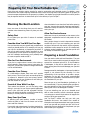
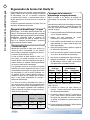
RCD and Wiring Requirements
The power supplied to the spa must be on a dedicated
RCD protected circuit with no other appliances or
lights sharing the power.
Use copper wire with THHN insulation. Do not use
aluminum wire.
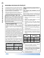
Use the table below to determine your GFCI and wiring
requirements.
When wires larger than #6 AWG are required, install
a junction box near the spa and use #6 AWG wire
between the junction box and the spa.
Wire runs over 26 m must increase wire gauge to the
next lower number. For example: A normal 50 amp
RCD with four #8 AWG copper wires run over 26
m would require you to go to four #6 AWG copper
wires.
Testing the RCD Breaker
Test the RCD breaker prior to rst use and periodically
when the spa is powered. To test the RCD breaker
follow these instructions (spa should be operating):
Press the TEST button on the RCD. The RCD will 1.
trip and the spa will shut off.
Reset the RCD breaker by switching the breaker 2.
to the full OFF position, wait a moment, then turn
the breaker back on. The spa should have power
again.
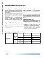
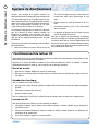
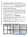
230 Volt Electrical Installation
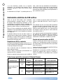
All portable spas (except Fitness Spas)
Spa Model
Control
Box Services GFCI Required Wires Required
All portable spas
(except Fitness Spas)
6115 and
6215
Single
One 32 amp RCD or one
16 amp RCD
Three #10 AWG copper
wires
Dual Two 16 amp RCDs
Five #10 AWG copper
wires
8015
Single
One 32 amp RCD or one
16 amp RCD
Three #10 AWG copper
wires
Dual Two 16 amp RCDs
Five #10 AWG copper
wires

2012 Portable Spa
LTR20121001, Rev. A
Preparing for Your New Portable Spa
www. c a l s p a s. c o m
5
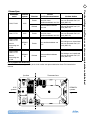
Fitness Spas
Spa Model
Control
Box Services GFCI Required Wires Required
F1239, F1439 6215
Single
One 32 amp RCD or one
16 amp RCD
Three #10 AWG copper
wires
Dual Two 16 amp RCDs
Five #10 AWG copper
wires
F1640, F1770 8015 P4 Single
One 32 amp RCD or one
16 amp RCD
Three #10 AWG copper
wires
F1239, F1439, F1640,
F1770
with 2.5 kW heater
OE9905
P4
Single One 32 amp RCD
Three #10 AWG copper
wires
F1239, F1439, F1640,
F1770
with 8.5 kW heater
OE9905
P4
Dual Two 32 amp RCDs
Six #10 AWG copper
wires
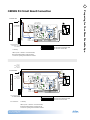
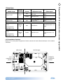
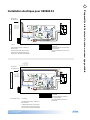
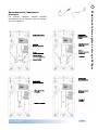
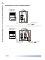
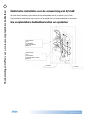
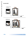
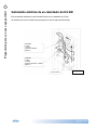
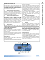
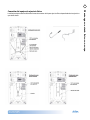
F1770 electrical connection
Model F1770 has two equipment packs. Each one requires a separate electrical service. See the diagram
below.
Spa side
6115
control box
OE9905 P4
control box
Swim side

2012 Portable Spa
LTR20121001, Rev. A
Preparing for Your New Portable Spa
www. c a l s p a s. c o m
6
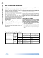
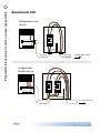
GREEN / YELLOW
BROWN (Hot)
BLUE (Neutral)
BROWN (Hot)
BLUE (Neutral)
BROWN (Hot)
BLUE (Neutral)
BLUE
(Neutral)
BLUE
(Neutral)
BLUE
(Neutral)
BLUE
(Neutral)
To control box
Three service
conguration
Three service
conguration
BLUE
(Neutral)
BLUE
(Neutral)
BLUE
BLUE
BROWN
(Hot)
BROWN
(Hot)
BROWN
GREEN / YELLOW (Ground)
To control box
BROWN (Hot)
BROWN (Hot)
Two service
conguration
BLUE
(Neutral)
BLUE
(Neutral)
BROWN
(Hot)
BROWN
(Hot)
GREEN / YELLOW (Ground)
BROWN (Hot)
BLUE (Neutral)
BLUE (Neutral)
GREEN / YELLOW (Ground)
GREEN / YELLOW (Ground)
One service
conguration
To control box
GREEN / YELLOW
BROWN (Hot)
BLUE (Neutral)
Three phase
conguration
RCD Wiring Diagram

2012 Portable Spa
LTR20121001, Rev. A
Preparing for Your New Portable Spa
www. c a l s p a s. c o m
7
T
B
1
H
T
R
2
J
101
00
H
TR
1
G
N
J
50
T1
J1
J2
J10
J
57
J58
J58
J
71
1
0VA
C
10VAC
J46
J46
J
2
5
5
J
2
6
6
J
72
J
9
0
J28
8
J28
J
1
A
J
2A
J
3
2
2
J
52
J
5
1
J
F
6, T30A 480
V
AV
O
ZON
E
PUM
P
1
O
PT. BLWR
/
P
U
MP 2
C
IR
C
. P
U
M
P
K1
K3
K4
K
6
E
.
G
ND
J
47
G
N
G
N
G
N
J
29
J
2
3
G
N
J17/2
6
K
2
K9
J
2
0
G
N
W2
1
2
3
4
W1
B
alboa
B
ALBOA INSTRUMENTS, INC.
G
S500
Z
C
OPYRIGHT 2007
MADE IN U.S.A
.
P
/N 22015_
B
J
60
J44
J
1
8
1
1
1
1
1
1
1
J
7
J8
EX
T R
LY
TST
J6
SEN A
V
A
C
S
EN
B
J
2
2
J4
3
AUX
F
J
1
3
J
11
J1
2
J
1
9
F2
S
1
S
WIT
C
HBANK A
K8
K5
C
9
U
4
F3
A
250
V
F
7
F1
F
10
A
250
V
F
4
,
T0.2
A
250
V
Pb
b
P
P
F3
To an optional
fuse-protected
expansion board
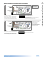
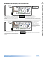
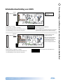
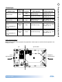
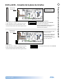
DIP Switch A10 must be OFF.
Three Phase Service
GREEN/
YELLOW
(Ground)
BROWN (Hot)
BROWN (Hot)
BLUE (Neutral)
BROWN (Hot)
From RCD Box
GROUND TERMINAL BLOCK
(ATTACHED TO OUTSIDE
OF SYSTEM BOX)
O
N
SWITCHBANK
1
2
3 4
5 6
7
8 9
10
For 1 x 16 Amp Service:
DIP Switch A10 must be ON.
For 1 x 32 Amp Service:
Set DIP Switch A10 such that total system amperage
draw never exceeds rated service input.
Completely remove the white
wire from J26 and J32, or J25.
Completely remove the blue wire
from J28 and J59.
3 x 16 Amp
5 Wires (3 Lines + 1 Neutrals + 1 Protective Earth)
Protective Earth wire (Green / Yellow) must be
connected to system ground terminal as marked.
IMPORTANT: Service MUST include a neutral wire
with a line to neutral voltage of 230VAC.
If an expansion board is installed,
black wire must connect to J28
(Line 2) only.
J
1
J
2
J
1
0
J
71
1
0VA
C
10VAC
J46
J46
J
7
2
J
1
A
J
2A
O
PT. BLWR
/
P
U
MP 2
G
N
6
J
2
0
G
N
J
60
J44
J
1
8
1
1
1
1
1
1
1
J
7
J8
EX
T R
LY
T
ST
J
6
SEN A
VA
C
S
EN
B
J
2
2
J
43
AUX
F
J11
J
1
2
J
19
K8
K5
C
9
U4
F3A
2
50V
F
10
A
250
V
F3
J
52
T
B
1
H
T
R
2
J
101
00
H
TR
1
G
N
J
50
T1
J
57
J58
J58
J
2
5
5
J
2
6
6
J
9
0
J28
8
J28
J
3
2
2
J
51
J
F
6, T30
A
480
V
O
Z
O
N
E
PUM
P
1
C
IR
C
. P
U
M
P
K1
K3
K4
K
6
E
.
G
ND
J
47
G
N
G
N
G
N
J
2
9
J
2
3
J17/2
K2
K9
W2
1
2
3
4
W1
B
alboa
B
ALB
O
A IN
S
TRUMENT
S,
IN
C
.
GS
500
Z
CO
PYRI
G
HT 2007
MADE IN U.
S
.A
.
P
/N 22015_
B
F2
S1
S
WIT
C
HBANK
A
F
4
,
T0.2
A
250
V
Pb
b
P
P
DIP Switch A10 must be OFF.
Dual Service
GREEN/
YELLOW
(Ground)
BLUE (Neutral)
BROWN (Hot)
BLUE (Neutral)
BROWN (Hot)
From RCD Box
O
N
SWITCHBANK
1 2 3 4 5 6 7 8 9 10
GROUND TERMINAL BLOCK
(ATTACHED TO OUTSIDE
OF SYSTEM BOX)
2 x 16 Amp
5 Wires (2 Lines + 2 Neutrals + 1 Protective Earth)
Protective Earth wire (Green / Yellow) must be
connected to system ground terminal as marked.
Completely remove the white
wire from J26 and J32.
Note: J32 and J25 are
electrically identical. The white
wire may be attached to either
terminal before removal.
Single Service
GREEN/
YELLOW
(Ground)
BLUE (Neutral)
BROWN (Hot)
From RCD Box
O
N
SWITCHBANK
1 2 3 4 5 6 7 8 9 10
J
1
J
2
J
1
0
J
71
10VAC
10VAC
J46
J46
J
7
2
J
1
A
J
2A
O
PT. BLWR/PUMP 2
G
N
J
17
/
2
6
J
2
0
G
N
J
1
8
1
J
43
J
1
3
HBANK
K8
K5
C
9
U4
F3A
2
50V
F7
F1
F
10
A
250
V
F
3
T1
J
9
0
P
UMP
1
K1
K3
K4
K6
E
.
G
ND
G
N
J
2
3
K2
K
9
F2
S1
S
WIT
C
T
B
1
H
T
R
2
J
101
00
H
TR
1
G
N
J
5
0
J
57
J58
J58
J
2
5
5
J
2
6
6
J28
8
J28
J
3
2
2
J
52
J
51
J
F
6
,
T30
A
480
V
AV
O
Z
O
N
E
C
IR
C
. P
U
M
P
J
47
G
N
G
N
J
2
9
W2
1
2
3
4
W1
B
alboa
B
ALB
O
A IN
S
TRUMENT
S,
IN
C
.
GS
500
Z
CO
PYRI
G
HT 2007
MADE IN U.
S
.A
.
P/
N 22015_
B
F
4, T0.2A 250
V
Pb
b
P
P
J
60
J44
1
1
1
1
1
1
J
7
J8
EX
T R
LY
T
ST
J
6
SEN A
VA
C
S
EN
B
J
2
2
AUX
F
J11
J
1
2
J
19
GROUND TERMINAL BLOCK
(ATTACHED TO OUTSIDE
OF SYSTEM BOX)
is is the factory
default configuration.
1 x 16 Amp or 1 x 32 Amp
3 Wires (1 Line + 1 Neutral + 1 Protective Earth)
Protective Earth wire (Green / Yellow) must be
connected to system ground terminal as marked.
6115 and 6215 Circuit Board Connection

2012 Portable Spa
LTR20121001, Rev. A
Preparing for Your New Portable Spa
www. c a l s p a s. c o m
8
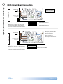
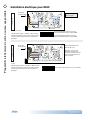
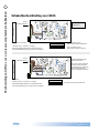
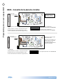
8015 Circuit Board Connection
DIP Switch A2 must be ON.
Three Phase Service
GREEN/
YELLOW
(Ground)
T
B
1
B
alboa
G
N
G
N
G
N
G
N
G
N
G
N
J68
J68
J101
J101
J100
J100
J
26
J53
J53
J99
J99
J97
J97
W
15
J27
J2
J2
J27
J32
J32
J
5
5
J9
0
J
1
T1
J
5
6
J
60
J
3
3
3
J41
J41
J45
J45
J
2
W1
F4
W
2
J
81
J30
J30
J
2
8
J
2
3
J
9
8
J54
J54
J54
J54
J
7
9
J9
5
J
94
J14
J14
J
5
7
J9
6
J
93
F6
F7
K7
K6
K8
F
US
E T30A 480
V
F
U
S
E F10A 250V
FUSE T30A 480
V
J
59
J
5
8
J5
K3
W4
K2
F5
J
3
J4
F2
F
US
E T0.2A
2
40V
K4
K11
K10
K9
K1
J
9
G
W3
BALBOA INSTRUMENTS, INC
.
GL2000 T
C
MA
C
H 3
P
/
N 22898 REV D
CO
PYRIGHT 2006
M
ADE IN U.S.A.
J
13
J
1
5
J7
J
82
J
22
J
24
EX
T RE
LAY
J6
EXT 2
S
P3
AU
X
F
A
L
ARM
S
EN A VA
C
S
EN
B
J
91
TS
T
S
WIT
C
HBANK
A
FUSE F3A 250
V
A
D
CM
MAIN
P
ANE
L
MAIN
P
ANE
L
MAIN
PAN
E
L
AUX
PAN
E
L
A
U
X
PAN
E
L
R
EM
O
T
E
J
6
9
J20
J
7
1
J
7
2
J
70J10J39
F1
H
TR
H
2
H
TR1
H
E
XT I
/O
J
36
J
8
3.0kW
From RCD Box
GROUND TERMINAL BLOCK
(ATTACHED TO OUTSIDE
OF SYSTEM BOX)
For 1 x 16 Amp Service:
DIP Switch A2 must be ON.
For 1 x 32 Amp Service:
DIP Switch A2 must be OFF.
Completely remove the white
wire from J26 and J32.
Completely remove the blue wire
from J28 and J57.
3 x 16 Amp
5 Wires (3 Lines + 1 Neutrals + 1 Protective Earth)
Protective Earth wire (Green / Yellow) must be
connected to system ground terminal as marked.
IMPORTANT: Service MUST include a neutral wire
with a line to neutral voltage of 230VAC.
O
N
SWITCHBANK
1 2 3 4 5 6 7 8 9 10 11 12
DIP Switch A2 must be ON.
Dual Service
GREEN/
YELLOW
(Ground)
T
B
1
B
alboa
G
N
G
N
G
N
G
N
G
N
G
N
J68
J68
J101
J101
J100
J100
J
26
J53
J53
J99
J99
J97
J97
W
15
J27
J2
J2
J27
J32
J32
J
5
5
J9
0
J
1
T1
J
5
6
J
60
J
3
3
3
J41
J41
J45
J45
J
2
W1
F4
W
2
J
81
J30
J30
J
2
8
J
2
3
J
9
8
J54
J54
J54
J54
J
7
9
J9
5
J
94
J14
J14
J
5
7
J9
6
J
93
F6
F7
K7
K6
K8
F
US
E T30A 480
V
F
U
S
E F10A 250V
FUSE T30A 480
V
J
59
J
5
8
J5
K3
W4
K2
F5
J
3
J4
F2
F
US
E T0.2A
2
40V
K4
K11
K10
K9
K1
J
9
G
W3
BALBOA INSTRUMENTS, INC
.
GL2000 T
C
MA
C
H 3
P
/
N 22898 REV D
CO
PYRIGHT 2006
M
ADE IN U.S.A.
J
13
J
1
5
J7
J
82
J
22
J
24
EX
T RE
LAY
J6
EXT 2
S
P3
AU
X
F
A
L
ARM
S
EN A VA
C
S
EN
B
J
91
TS
T
S
WIT
C
HBANK
A
FUSE F3A 250
V
A
D
CM
MAIN
P
ANE
L
MAIN
P
ANE
L
MAIN
PAN
E
L
AUX
PAN
E
L
A
U
X
PAN
E
L
R
EM
O
T
E
J
6
9
J20
J
7
1
J
7
2
J
70J10J39
F1
H
TR
H
2
H
TR1
H
E
XT I
/O
J
36
J
8
3.0kW
From RCD Box
GROUND TERMINAL BLOCK
(ATTACHED TO OUTSIDE
OF SYSTEM BOX)
2 x 16 Amp
5 Wires (2 Lines + 2 Neutrals + 1 Protective Earth)
Protective Earth wire (Green / Yellow) must be
connected to system ground terminal as marked.
Completely remove the white
wire from J26 and J32.
Note: J32 and J23 are
electrically identical. The white
wire may be attached to either
terminal before removal.
O
N
SWITCHBANK
1 2 3 4 5 6 7 8 9 10 11 12
Single Service
GREEN/
YELLOW
(Ground)
From RCD Box
O
N
SWITCHBANK
1 2 3 4 5 6 7 8 9 10 11 12
T
B
1
B
alboa
G
N
G
N
G
N
G
N
G
N
G
N
J68
J68
J101
J101
J100
J100
J
26
J53
J53
J99
J99
J97
J97
W
15
J27
J2
J2
J27
J32
J32
J
5
5
J9
0
J
1
T1
J
5
6
J
60
J
3
3
3
J41
J41
J45
J45
J
2
W1
F4
W
2
J
81
J30
J30
J
2
8
J
2
3
J
9
8
J54
J54
J54
J54
J
7
9
J9
5
J
94
J14
J14
J
5
7
J9
6
J
93
F6
F7
K7
K6
K8
F
US
E T30A 480
V
F
U
S
E F10A 250V
FUSE T30A 480
V
J
59
J
5
8
J5
K3
W4
K2
F5
J
3
J4
F2
F
US
E T0.2A
2
40V
K4
K11
K10
K9
K1
J
9
G
W3
BALBOA INSTRUMENTS, INC
.
GL2000 T
C
MA
C
H 3
P
/
N 22898 REV D
CO
PYRIGHT 2006
M
ADE IN U.S.A.
J
13
J
1
5
J7
J
82
J
22
J
24
EX
T RE
LAY
J6
EXT 2
S
P3
AU
X
F
A
L
ARM
S
EN A VA
C
S
EN
B
J
91
TS
T
S
WIT
C
HBANK
A
FUSE F3A 250
V
A
D
CM
MAIN
P
ANE
L
MAIN
P
ANE
L
MAIN
PAN
E
L
AUX
PAN
E
L
A
U
X
PAN
E
L
R
EM
O
T
E
J
6
9
J20
J
7
1
J
7
2
J
70J10J39
F1
H
TR
H
2
H
TR1
H
E
XT I
/O
J
36
J
8
3.0kW
GROUND TERMINAL BLOCK
(ATTACHED TO OUTSIDE
OF SYSTEM BOX)
is is the factory
default conguration.
1 x 16 Amp or 1 x 32 Amp
3 Wires (1 Line + 1 Neutral + 1 Protective Earth)
Protective Earth wire (Green / Yellow) must be
connected to system ground terminal as marked.

2012 Portable Spa
LTR20121001, Rev. A
Preparing for Your New Portable Spa
www. c a l s p a s. c o m
9
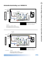
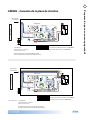
OE9905 P4 Circuit Board Connection
Two Services
One Service
T
B
1
B
alboa
G
N
G
N
G
N
G
N
G
N
G
N
J68
J68
J101
J101
J100
J100
J
2
6
J53
J53
J99
J99
J97
J97
W
1
5
J27
J2
J2
J27
J32
J32
J5
5
J
9
0
J1
T1
J56
J
60
J
3
3
3
J41
J41
J45
J45
J2
W1
F4
W2
J
8
1
J31
J31
J
12
J30
J30
J
28
J
2
3
J98
J54
J54
J54
J54
J
79
J
95
J
94
J14
J14
J
5
7
J
9
6
J
9
3
F6
F
7
K7
K6
K
8
FU
S
E T30A 480V
F
US
E F10A 250V
F
U
S
E T30A 480V
J
5
9
J
5
8
J
5
K3
W
4
K2
F5
J3
J
4
F
2
F
US
E T0.3A
240
V
K4
K11
K10
K9
K1
J
9
NG
W3
BALBOA INSTRUMENTS, INC.
GL2000TC MACH 3
P
/
N 22898 REV
D
CO
PYRI
G
HT 2006
MADE IN
U
.
S
.A
.
J
1
3
J
1
5
J
17
J
82
J
2
2
J
24
EXT RELAY
J
6
EXT 2S P3
AUX F
ALA
R
M
S
EN
A
VA
C
S
EN
B
J8
3
J
9
1
C
F
G
J
17
T
S
T
S
WIT
C
HBANK A
S
WIT
C
HBANK B
F
USE F3A 250V
ADC
M
MAIN
PAN
E
L
M
AI
N
PANEL
MAIN
P
AN
E
L
AU
X
P
AN
E
L
A
UX
PAN
EL
R
EMOTE
J69
J
20
J71 J72
J70J1
0
J
39
F1
H
T
R
H
2
HTR1
H
EXT I
/O
J36
J
8
Ozone
Configuration
Settings
Enabled
RTC
Enabled
A.V.
Spa
Light
Blower
Use X-P CE or X-P231 CE
Expander for Pump 3 1-Speed
2-Spd P1
3.0 kW
3.0kW
Heater rated @ 230V
J8 must be Jumpered
DIP Switch A2 can be ON.
DIP Switch A3 and A4 must be OFF.
DIP Switch A11 must be ON.
O
N
1
2
3 4
5
6
7
8 9 10 11 12
GREEN/
YELLOW
(Ground)
BLUE (Neutral)
BROWN (Hot)
From RCD Box
GROUND TERMINAL BLOCK
(ATTACHED TO OUTSIDE
OF SYSTEM BOX)
1 x 32 Amp
3 Wires (1 Line + 1 Neutral + 1 Protective Earth)
Protective Earth wire (Green / Yellow) must be
connected to system ground terminal as marked.
Brown - NEUTRAL
Black - HOT
Yellow - GROUND
T
B
1
B
alboa
G
N
G
N
G
N
G
N
G
N
G
N
J68
J68
J101
J101
J100
J100
J
2
6
J53
J53
J99
J99
J97
J97
W
1
5
J27
J2
J2
J27
J32
J32
J5
5
J
9
0
J1
T1
J56
J
60
J
3
3
3
J41
J41
J45
J45
J2
W1
F4
W2
J
8
1
J31
J31
J
12
J30
J30
J
28
J
2
3
J98
J54
J54
J54
J54
J
79
J
95
J
94
J14
J14
J
5
7
J
9
6
J
9
3
F6
F
7
K7
K6
K
8
FU
S
E T30A 480V
F
US
E F10A 250V
F
U
S
E T30A 480V
J
5
9
J
5
8
J
5
K3
W
4
K2
F5
J3
J
4
F
2
F
US
E T0.3A
240
V
K4
K11
K10
K9
K1
J
9
NG
W3
BALBOA INSTRUMENTS, INC.
GL2000TC MACH 3
P
/
N 22898 REV
D
CO
PYRI
G
HT 2006
MADE IN
U
.
S
.A
.
J
1
3
J
1
5
J
17
J
82
J
2
2
J
24
EXT RELAY
J
6
EXT 2S P3
AUX F
ALA
R
M
S
EN
A
VA
C
S
EN
B
J8
3
J
9
1
C
F
G
J
17
T
S
T
S
WIT
C
HBANK A
S
WIT
C
HBANK B
F
USE F3A 250V
ADC
M
MAIN
PAN
E
L
M
AI
N
PANEL
MAIN
P
AN
E
L
AU
X
P
AN
E
L
A
UX
PAN
EL
R
EMOTE
J69
J
20
J71 J72
J70J1
0
J
39
F1
H
T
R
H
2
HTR1
H
EXT I
/O
J36
J
8
Ozone
Configuration
Settings
Enabled
RTC
Enabled
A.V.
Spa
Light
Blower
Use X-P CE or X-P231 CE
Expander for Pump 3 1-Speed
2-Spd P1
3.0 kW
3.0kW
Heater rated @ 230V
J8 must be Jumpered
J1
J3
J1
J3
DIP Switch A2 can be ON.
DIP Switch A3 and A4 must be OFF.
DIP Switch A11 must be ON.
O
N
1
2
3 4
5
6
7
8 9
10
11
12
GREEN/
YELLOW
(Ground)
GREEN/
YELLOW
(Ground)
BLUE (Neutral)
BLUE (Neutral)
BROWN (Hot)
BROWN
(Hot)
From RCD Box
GROUND TERMINAL BLOCK
(ATTACHED TO OUTSIDE
OF SYSTEM BOX)
1 x 32 Amp
3 Wires (1 Line + 1 Neutral + 1 Protective Earth)
Protective Earth wire (Green / Yellow) must be
connected to system ground terminal as marked.
Service 1:
Brown - NEUTRAL
Black - HOT
Yellow - GROUND
Service 2:
Brown - NEUTRAL
Black - HOT
Yellow - GROUND
For each service:

2012 Portable Spa
LTR20121001, Rev. A
Preparing for Your New Portable Spa
www. c a l s p a s. c o m
10
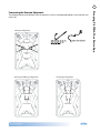
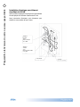
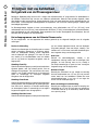
SERVICE 2
INPUT POWER 32 AMPS
2 WIRES
HOT, NEUTRAL
AWG # 10
SERVICE
INPUT POWER 32 AMPS
3 WIRES
HOT, NEUTRAL, GROUND
AWG # 10
3.0 KW OUT
5.5 KW IN
Electrical Installation for 8.5 kW Heater
This applies to Ultimate Fitness spas with the 8.5 kW heater only.
Two electrical services are required to heat the swim side of the Fitness Spa.

2012 Portable Spa
LTR20121001, Rev. A
Preparing for Your New Portable Spa
www. c a l s p a s. c o m
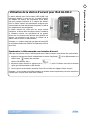
11
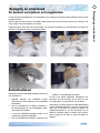
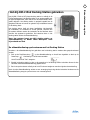
Filling and Powering Up Your Portable Spa
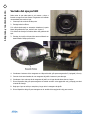
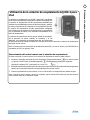
Open the air relief valve (located next to the two 6.
lters, if equipped) after the air bubbles stop
coming out of it. Close the valve hand-tight.
Once the water is at the correct level and air is 7.
bled, turn on the power at the RCD breaker.
NOTE: When the power is turned on to the spa, it
will perform a diagnostic check for approximately ve
minutes. When the diagnostic is complete, the spa
will automatically operate at lter speed and continue
heating until the spa water temperature reaches the
default temperature of 37.5˚C.
If no water is owing when the pump is running 8.
there could be an air pocket at the suction side of
the pump. Shut off power to the spa and loosen
the pump union on the suction side of the pump
to bleed the air. When air is bled, turn power
back on.
Re-install the lter and the lter basket into the 9.
skimmer/lter canister.
The spa is now ready for use.
NOTE: Never run the spa with the gate valves closed
or without water circulating for long periods of time.
Be careful not to over-tighten the plumbing ttings.
Never ll your spa with soft water. Soft water makes it
impossible to maintain the proper water chemistry and
may cause the water to foam, which will ultimately
harm the nish of the spa and void your warranty.
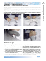
Once the spa has been placed on an approved 1.
surface and has been correctly wired by a licensed
electrician, inspect all plumbing connections in the
equipment area of your spa. Ensure that these
connections are secure and that they did not
loosen during shipment.
If equipped, open all gate valves in the equipment 2.
area. Before operating the spa, these valves must
be in the UP or OPEN position.
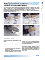
Remove the lter basket and cartridge from 3.
skimmer/lter canister.
Place a garden hose in the skimmer/lter canister 4.
and ll your spa with regular tap water to the
proper water level (halfway up the skimmer
area).
(For owners of the automatic bromine generator) 5.
Make sure the dial on the face of the bromine
generator unit is turned to the OFF position.

2012 Portable Spa
LTR20121001, Rev. A
Operating Your Spa
www. c a l s p a s. c o m
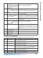
12
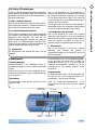
Initial Start up
When rst powered up, it will automatically revert to
Priming mode. A Pr on the topside display will indicate
this. Priming mode will be active for less than ve
minutes at which time the heater will be activated and
the water temperature will be maintained in Standard
mode. The spa will heat to 37.5°C at start up until the
set temperature is changed as described below.
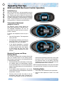
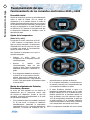
Temperature Adjustment
(Range 26°C to 40°C)
The electronic control panels display the
actual water temperature in degrees Celsius.
The displayed temperature will only be
current after the pump has been running for
at least 2 minutes.
To display the temperature that the spa is
set to:
Press the Temp button. The temperature •
setting will ash.
While the display is ashing, each time you •
press Temp button, the set temperature
will change up or down one degree.
If the desired temperature is opposite •
of the direction each press of the button
is making, release button, allow display
to stop ashing and then press Temp
button to change temperature the other
direction.
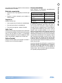
Standard, Economy and Sleep
Heating Modes
Your new spa is equipped with a heating feature that
gives you complete control of the heating system.
When the spa is powered up, it will automatically start
in standard heating mode.
St will light briey on the main display. In this mode, •
the heating system will automatically maintain
the set spa temperature. In the economy-heating
mode, the heating system will only activate during
ltration times.
Ec will display solid if temperature is not current •
and will alternate with spa temperature if measured
temperature is current.
Economy mode will heat the water to the set •
temperature while Sleep mode, indicated by a
SL on the main display, will also only activate the
6105 and 6205 Electronic Control Operation
Operating Your Spa
heater during the ltering cycles but will only heat
the water to within 10°C of the set temperature.
Like Economy mode, SL will display solid when
temperature is not current and will alternate with
actual temperature when it is current.
NOTE: Displayed temperature will only be current after
the pump has been running for at least two minutes.
Switching Modes
Press Temp button followed by the Light button.•
Press the same sequence to switch to the next •
mode.

2012 Portable Spa
LTR20121001, Rev. A
Operating Your Spa
www. c a l s p a s. c o m
13
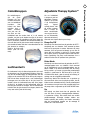
Jets
Press the Jets button:
Once to activate low speed pump.•
Twice to activate high speed.•
Three times to return to turn pump off.•
Automatic Time outs
These features will automatically turn themselves off
during periods of continuous use:
Low speed pump After 4 hours•
High speed pumps After 15 minutes•
Optional circulation pump After 15 minutes•
Optional turbo After 15 minutes•
Spa light After 15 minutes•
Light
Press the Light button to turn on the light. Press it
once again to turn the light off. All optional lighting
such as the control panel light and cabinet perimeter
lighting is controlled by the Light button and will turn
on and off with the spa light.
Option
Press the Option button to turn on the pump 2 on.
Press it once again to turn off the pump 2 off.
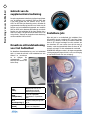
Setting Filtration Cycles
Your spa is programmed to lter twice a day. The rst
cycle will begin 6 minutes after the spa is turned on
and the second cycle 12 hours later. The factory has
programmed the cycle to last for 2 hours but this can
be switched to 4, 6, or 8 hours depending on your
requirements. To set ltration time, turn off the power
to the spa at the time of day you would like one of the
ltration cycles to begin then turn back on after 30
seconds. When power has been restored, press the
“Temp” button then the “Jets” button. Press “Temp”
button again to change the ltering cycle duration.
When desired duration is selected press the “Jets”
button to exit.
At the beginning of each ltering cycle the Turbo system
will run for approximately 30 seconds. The low speed
pump will run for the duration of the ltering cycle
and if an Ozone system is installed it will be activated.
During ltering, “FC” will appear on the main display.

2012 Portable Spa
LTR20121001, Rev. A
Operating Your Spa
www. c a l s p a s. c o m
14
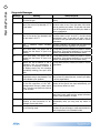
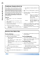
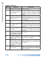
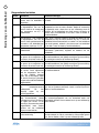
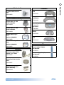
Diagnostic Messages
Message Meaning
-- Spa temperature is unknown. After pump has been running for 2 minutes temperature will
be displayed.
HH Overheat protection (spa is shutdown) DO NOT ENTER THE WATER! One sensor has detected
118˚F (48˚C) at the heater. Remove the spa cover and allow spa to cool below 107˚F (42˚C).
Press any button on the topside display to reset spa. If spa will not reset after spa has cooled,
turn off power for approximately 30 seconds and then turn power back on. If display message
is repeated then shut the power off to the spa and call your dealer or service organization.
OH Overheat protection (spa is shutdown) DO NOT ENTER THE WATER! If the spa has reached
110˚F (43˚C), remove the spa cover to cool the water. At 107˚F (42˚C), the spa should reset
itself. If the spa does not reset, then shut the power off to the spa, wait 30 seconds and
restore power to spa. If display message is repeated then shut the power off to the spa and
call your dealer or service organization.
IC A possible ice condition exists within the spa. No action is required, the pump will automatically
activate.
SA or Sb Spa is shut down. Spa has detected that one of the sensors is not operating properly. One
of these may display briey during overheat then disappear when overheat situation has been
resolved. Call your dealer or service organization if message does not go away.
Sn Sensor (Spa is shut down). The high limit or water temperature sensors are not working
correctly. Call your dealer or service organization.
HL A difference in readings between temperature sensors has been detected indicating a possible
water ow problem. Make sure spa is lled to proper level and that pumps are primed (water
is owing). Also check to make sure lter cartridges are clean. If message does not reset, call
your dealer or service organization.
LF This will display on the 5th occurrence of the “HL” message in 24 hours indicating a persistent
ow problem. The heater will be shut down but other functions will continue to operate.
Follow “HL” message actions then press any button to reset.
dr Insufcient water ow through the heater has been detected. Spa will be shut down for
15 minutes. Check water level and ll spa if water level is low. Make sure pumps are
primed (water is owing) and lter cartridges are clean. Press any button to reset or wait 15
minutes and spa will automatically reset. If message does not reset, call your dealer or service
organization.
dY Insufcient water level detected in heater. This will display on the 3rd occurrence of “dr”
message. Follow directions for “dr” message and press any button to reset spa. Spa will not
automatically reset when “dY” is displayed.
Sf Safety Suction System (Spa is shut down). The display will show “Sf” as soon as the vacuum
switch closes. All functions will turn off and the system will be disabled until a panel button is
pressed.
ST Indicates heater is in standard mode
Ec Indicates heater is in economy mode
SL Indicates heater is in sleep mode

2012 Portable Spa
LTR20121001, Rev. A
Operating Your Spa
www. c a l s p a s. c o m
15
When rst powered up, the electronic system will
perform a self-diagnostic check and then it will
automatically heat to and maintain a temperature of
37.5˚C until you change the set temperature as listed
in the “Temperature Adjustment” section below.
These instructions will describe features and options
that your particular spa may not be equipped with.
Initial Start-up
When your spa is rst powered up, it displays some
conguration codes and then goes into priming mode
(Pr will appear on the display panel). This mode lasts
up to four minutes and then the spa begins to heat to
its pre -programmed temperature of 37.5˚C. You can
exit the priming mode early by pressing UP or DOWN
buttons.
Temperature Adjustment (26.0˚C -
40.0˚C)
The start-up temperature is set at 37.5˚C. The last
measured temperature is constantly displayed on
the control panel. Note that the last measured spa
temperature is displayed. The displayed temperature
will be updated when the pump has been running for
at least two minutes.
Press the UP or DOWN buttons once to display the
set temperature. Each time either button is pressed
again, the set temperature will increase or decrease
depending on which button is pressed. After three
seconds, the control panel will automatically display
the last measured spa temperature.
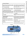
8005 and 9005 Electronic Control Operation
Time
When time hasn’t been programmed, the TIME icon
ashes. To set the time, press the TIME button and
then the MODE/PROG button. Use the UP and DOWN
buttons to adjust time. See the next page for more
detailed instructions.
Auxiliary controls

2012 Portable Spa
LTR20121001, Rev. A
Operating Your Spa
www. c a l s p a s. c o m
16
Standard, Economy, Sleep, and
Standby Modes
Mode/Prog: This button is used to switch between
standard, economy, and sleep modes.
Press MODE/PROG to enter mode programming.1.
Press the DOWN button to cycle through to the 2.
desired mode.
Press MODE/PROG to conrm selection.3.
Standard Mode: This is programmed to maintain the
desired temperature. Note that the last measured
spa temperature displayed is current only when the
pump has been running for at least two minutes. The
“STAND” icon will display until the mode is changed.
Economy Mode: Economy mode heats the spa to the
set temperature only during lter cycles. The “ECON”
icon will display until the mode is changed. Pressing
the JETS 1 button while in economy mode puts the
spa in standard-in-economy mode, which operates the
same as standard mode but reverts back to economy
mode automatically after one hour. During this
time, pressing the MODE/PROG button will revert to
economy mode immediately.
Sleep Mode: Sleep mode heats the spa to within 11˚C
of the set temperature only during lter cycles. The
“SLEEP” icon will display until the mode is changed.
Standby Mode: Pressing “Warm” or “Cool” then “Jets
2” will turn off all spa functions temporarily. This is
helpful when changing a lter. Pressing any button
resets the spa.
Jets 1 and Jets 2
Press the JETS 1 button once to turn pump 1 on or off
and to shift between low and high speeds if equipped.
If left running, the low speed turns off after two hours
and the high speed turns off after 15 minutes. On
non-circulation systems, the low speed of pump 1
runs when the blower or any other pump is on. It may
also activate for at least two minutes every 30 minutes
to detect the spa temperature and then to heat to
the set temperature if needed, depending upon the
mode. When the low speed turns on automatically, it
cannot be deactivated from the panel; however, the
high speed may be started.
Option (Optional Blower)
Press the OPTION button to turn the optional
equipment on and off. If left on, the equipment will
automatically turn off after 15 minutes.
Light
Press the LIGHT button to turn the spa light on and
off.
Invert
Press the INVERT button to change the numbers in the
display to read upside down. Another press returns
the display to the right-side-up position. This enables
you to read the display while you are in the spa.
Locking the Panel
To lock the panel:
Press TIME, JETS 1, and the UP button within three
seconds. When locked, the panel will display “LOCK”.
All buttons are frozen except the TIME button.
To unlock the panel:
Press TIME, JETS ,1 then the DOWN button within
three seconds.
Setting the Temperature Lock
To activate the temperature lock:
Press the UP or DOWN button, TIME, JETS 1, then the
UP button within three seconds. The panel will display
“TEMP LOCK” when the set temperature is locked.
To unlock the set temperature:
Press the UP or DOWN button, TIME, JETS 1, then the
DOWN button..
Circulation Pump (optional)
If your system is equipped with a circulation pump,
it may be congured to work in one of two different
ways:
The circulation pump operates continuously (24 1.
hours) with the exception of turning off for 30
minutes at a time when the water temperature
reaches 1.7˚C above the set temperature (most
likely to happen in very hot climates).
The circulation pump will come on when the 2.
system is checking temperature, during lter
cycles, during freeze conditions, or when another
pump is on.
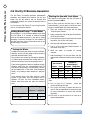
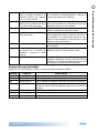
Preset Filter Cycles
There are two lter cycles per day. The start and end
times of each cycle are programmable. To program, set
the time as instructed above, then press MODE/PROG
to advance to the next setting (or to exit after the last
setting). The default lter cycles are as follows:

2012 Portable Spa
LTR20121001, Rev. A
Operating Your Spa
www. c a l s p a s. c o m
17
The rst lter cycle is automatically activated at •
8:00 AM and operates the pump until 10:00 AM.
The “FILTER 1” indicator icon will light when lter
1 is running.
The second lter cycle is automatically activated •
at 8:00 PM and operates the pump until 10:00 PM.
The “FILTER 2” indicator icon will light when lter
2 is running.
The pump and the ozone generator will run during
ltration. At the start of each lter cycle, the blower
will run on highest speed for 30 seconds to clean out
the air channels. The lowest speed of pump 2 and
pump 3 will run for ve minutes. In the event of power
loss or shut down, the time of day will need to be
reset for lter cycles to run according to your desired
programming.
Clean-up Cycle
When the pump or blower is turned on by a button
press, a clean-up cycle begins 30 minutes after the
pump or blower is turned off or times out. The pump
and the ozone generator will run for one hour.
Ozone (optional)
On most systems, the ozone generator (if installed)
runs during lter cycles (except when pump 1 is
operating at high speed on a non-circulation system)
and during clean-up cycles. On some systems, the
ozone generator operates whenever the pump runs.
If your system is congured with the optional ozone
disable feature, the ozone generator will turn off for
one hour any time a function button (JETS 1, JETS 2,
OPTION etc.) is pressed.
Freeze Protection
If the temperature sensors detect a drop to 6.7˚C
within the heater, the pump automatically activates
to provide freeze protection. The equipment stays
on until four minutes after the sensors detect that
the spa temperature has risen to 7.2˚C or higher. In
colder climates, an optional additional freeze sensor
may be added to protect against freeze conditions that
may not be sensed by the standard sensors. Auxiliary
freeze sensor protection acts similarly except with the
temperature thresholds determined by the switch and
without a four minute delay in turnoff.
Seite laden ...
Seite laden ...
Seite laden ...
Seite laden ...
Seite laden ...
Seite laden ...
Seite laden ...
Seite laden ...
Seite laden ...
Seite laden ...
Seite laden ...
Seite laden ...
Seite laden ...
Seite laden ...
Seite laden ...
Seite laden ...
Seite laden ...
Seite laden ...
Seite laden ...
Seite laden ...
Seite laden ...
Seite laden ...
Seite laden ...
Seite laden ...
Seite laden ...
Seite laden ...
Seite laden ...
Seite laden ...
Seite laden ...
Seite laden ...
Seite laden ...
Seite laden ...
Seite laden ...
Seite laden ...
Seite laden ...
Seite laden ...
Seite laden ...
Seite laden ...
Seite laden ...
Seite laden ...
Seite laden ...
Seite laden ...
Seite laden ...
Seite laden ...
Seite laden ...
Seite laden ...
Seite laden ...
Seite laden ...
Seite laden ...
Seite laden ...
Seite laden ...
Seite laden ...
Seite laden ...
Seite laden ...
Seite laden ...
Seite laden ...
Seite laden ...
Seite laden ...
Seite laden ...
Seite laden ...
Seite laden ...
Seite laden ...
Seite laden ...
Seite laden ...
Seite laden ...
Seite laden ...
Seite laden ...
Seite laden ...
Seite laden ...
Seite laden ...
Seite laden ...
Seite laden ...
Seite laden ...
Seite laden ...
Seite laden ...
Seite laden ...
Seite laden ...
Seite laden ...
Seite laden ...
Seite laden ...
Seite laden ...
Seite laden ...
Seite laden ...
Seite laden ...
Seite laden ...
Seite laden ...
Seite laden ...
Seite laden ...
Seite laden ...
Seite laden ...
Seite laden ...
Seite laden ...
Seite laden ...
Seite laden ...
Seite laden ...
Seite laden ...
Seite laden ...
Seite laden ...
Seite laden ...
Seite laden ...
Seite laden ...
Seite laden ...
Seite laden ...
Seite laden ...
Seite laden ...
Seite laden ...
Seite laden ...
Seite laden ...
Seite laden ...
Seite laden ...
Seite laden ...
Seite laden ...
Seite laden ...
Seite laden ...
Seite laden ...
Seite laden ...
Seite laden ...
Seite laden ...
Seite laden ...
Seite laden ...
Seite laden ...
Seite laden ...
Seite laden ...
Seite laden ...
Seite laden ...
Seite laden ...
Seite laden ...
Seite laden ...
Seite laden ...
Seite laden ...
Seite laden ...
Seite laden ...
Seite laden ...
Seite laden ...
Seite laden ...
Seite laden ...
Seite laden ...
Seite laden ...
Seite laden ...
Seite laden ...
Seite laden ...
Seite laden ...
Seite laden ...
Seite laden ...
Seite laden ...
Seite laden ...
Seite laden ...
Seite laden ...
Seite laden ...
Seite laden ...
Seite laden ...
Seite laden ...
Seite laden ...
Seite laden ...
Seite laden ...
Seite laden ...
Seite laden ...
Seite laden ...
Seite laden ...
Seite laden ...
Seite laden ...
Seite laden ...
Seite laden ...
Seite laden ...
Seite laden ...
Seite laden ...
Seite laden ...
Seite laden ...
Seite laden ...
Seite laden ...
Seite laden ...
Seite laden ...
Seite laden ...
Seite laden ...
Seite laden ...
Seite laden ...
Seite laden ...
Seite laden ...
Seite laden ...
Seite laden ...
Seite laden ...
Seite laden ...
Seite laden ...
Seite laden ...
Seite laden ...
Seite laden ...
Seite laden ...
Seite laden ...
Seite laden ...
Seite laden ...
Seite laden ...
Seite laden ...
Seite laden ...
Seite laden ...
Seite laden ...
Seite laden ...
Seite laden ...
Seite laden ...
Seite laden ...
Seite laden ...
Seite laden ...
Seite laden ...
Seite laden ...
Seite laden ...
Seite laden ...
Seite laden ...
Seite laden ...
Seite laden ...
Seite laden ...
Seite laden ...
Seite laden ...
Seite laden ...
Seite laden ...
Seite laden ...
Seite laden ...
Seite laden ...
Seite laden ...
Seite laden ...
Seite laden ...
Seite laden ...
Seite laden ...
Seite laden ...
Seite laden ...
Seite laden ...
Seite laden ...
Seite laden ...
Seite laden ...
Seite laden ...
Seite laden ...
Seite laden ...
Seite laden ...
Seite laden ...
Seite laden ...
Seite laden ...
Seite laden ...
Seite laden ...
Seite laden ...
Seite laden ...
Seite laden ...
Seite laden ...
Seite laden ...
Seite laden ...
Seite laden ...
Seite laden ...
Seite laden ...
Seite laden ...
Seite laden ...
Seite laden ...
Seite laden ...
Seite laden ...
Seite laden ...
Seite laden ...
Seite laden ...
Seite laden ...
Seite laden ...
Seite laden ...
Seite laden ...
Seite laden ...
Seite laden ...
Seite laden ...
Seite laden ...
Seite laden ...
Seite laden ...
Seite laden ...
Seite laden ...
Seite laden ...
Seite laden ...
Seite laden ...
Seite laden ...
Seite laden ...
Seite laden ...
Seite laden ...
Seite laden ...
Seite laden ...
Seite laden ...
Seite laden ...
Seite laden ...
Seite laden ...
Seite laden ...
Seite laden ...
Seite laden ...
Seite laden ...
Seite laden ...
Seite laden ...
Seite laden ...
Seite laden ...
Seite laden ...
Seite laden ...
Seite laden ...
Seite laden ...
Seite laden ...
Seite laden ...
Seite laden ...
-
 1
1
-
 2
2
-
 3
3
-
 4
4
-
 5
5
-
 6
6
-
 7
7
-
 8
8
-
 9
9
-
 10
10
-
 11
11
-
 12
12
-
 13
13
-
 14
14
-
 15
15
-
 16
16
-
 17
17
-
 18
18
-
 19
19
-
 20
20
-
 21
21
-
 22
22
-
 23
23
-
 24
24
-
 25
25
-
 26
26
-
 27
27
-
 28
28
-
 29
29
-
 30
30
-
 31
31
-
 32
32
-
 33
33
-
 34
34
-
 35
35
-
 36
36
-
 37
37
-
 38
38
-
 39
39
-
 40
40
-
 41
41
-
 42
42
-
 43
43
-
 44
44
-
 45
45
-
 46
46
-
 47
47
-
 48
48
-
 49
49
-
 50
50
-
 51
51
-
 52
52
-
 53
53
-
 54
54
-
 55
55
-
 56
56
-
 57
57
-
 58
58
-
 59
59
-
 60
60
-
 61
61
-
 62
62
-
 63
63
-
 64
64
-
 65
65
-
 66
66
-
 67
67
-
 68
68
-
 69
69
-
 70
70
-
 71
71
-
 72
72
-
 73
73
-
 74
74
-
 75
75
-
 76
76
-
 77
77
-
 78
78
-
 79
79
-
 80
80
-
 81
81
-
 82
82
-
 83
83
-
 84
84
-
 85
85
-
 86
86
-
 87
87
-
 88
88
-
 89
89
-
 90
90
-
 91
91
-
 92
92
-
 93
93
-
 94
94
-
 95
95
-
 96
96
-
 97
97
-
 98
98
-
 99
99
-
 100
100
-
 101
101
-
 102
102
-
 103
103
-
 104
104
-
 105
105
-
 106
106
-
 107
107
-
 108
108
-
 109
109
-
 110
110
-
 111
111
-
 112
112
-
 113
113
-
 114
114
-
 115
115
-
 116
116
-
 117
117
-
 118
118
-
 119
119
-
 120
120
-
 121
121
-
 122
122
-
 123
123
-
 124
124
-
 125
125
-
 126
126
-
 127
127
-
 128
128
-
 129
129
-
 130
130
-
 131
131
-
 132
132
-
 133
133
-
 134
134
-
 135
135
-
 136
136
-
 137
137
-
 138
138
-
 139
139
-
 140
140
-
 141
141
-
 142
142
-
 143
143
-
 144
144
-
 145
145
-
 146
146
-
 147
147
-
 148
148
-
 149
149
-
 150
150
-
 151
151
-
 152
152
-
 153
153
-
 154
154
-
 155
155
-
 156
156
-
 157
157
-
 158
158
-
 159
159
-
 160
160
-
 161
161
-
 162
162
-
 163
163
-
 164
164
-
 165
165
-
 166
166
-
 167
167
-
 168
168
-
 169
169
-
 170
170
-
 171
171
-
 172
172
-
 173
173
-
 174
174
-
 175
175
-
 176
176
-
 177
177
-
 178
178
-
 179
179
-
 180
180
-
 181
181
-
 182
182
-
 183
183
-
 184
184
-
 185
185
-
 186
186
-
 187
187
-
 188
188
-
 189
189
-
 190
190
-
 191
191
-
 192
192
-
 193
193
-
 194
194
-
 195
195
-
 196
196
-
 197
197
-
 198
198
-
 199
199
-
 200
200
-
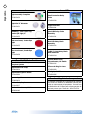 201
201
-
 202
202
-
 203
203
-
 204
204
-
 205
205
-
 206
206
-
 207
207
-
 208
208
-
 209
209
-
 210
210
-
 211
211
-
 212
212
-
 213
213
-
 214
214
-
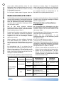 215
215
-
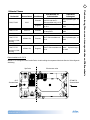 216
216
-
 217
217
-
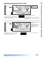 218
218
-
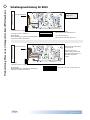 219
219
-
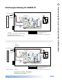 220
220
-
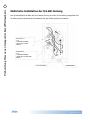 221
221
-
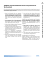 222
222
-
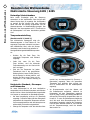 223
223
-
 224
224
-
 225
225
-
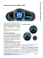 226
226
-
 227
227
-
 228
228
-
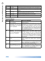 229
229
-
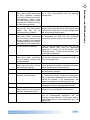 230
230
-
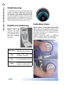 231
231
-
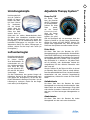 232
232
-
 233
233
-
 234
234
-
 235
235
-
 236
236
-
 237
237
-
 238
238
-
 239
239
-
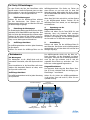 240
240
-
 241
241
-
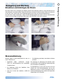 242
242
-
 243
243
-
 244
244
-
 245
245
-
 246
246
-
 247
247
-
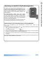 248
248
-
 249
249
-
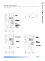 250
250
-
 251
251
-
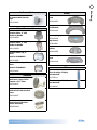 252
252
-
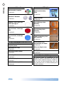 253
253
-
 254
254
-
 255
255
-
 256
256
-
 257
257
-
 258
258
-
 259
259
-
 260
260
-
 261
261
-
 262
262
-
 263
263
-
 264
264
-
 265
265
-
 266
266
-
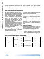 267
267
-
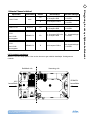 268
268
-
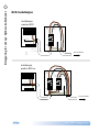 269
269
-
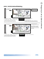 270
270
-
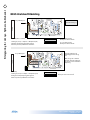 271
271
-
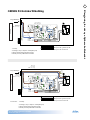 272
272
-
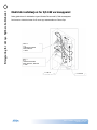 273
273
-
 274
274
-
 275
275
-
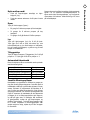 276
276
-
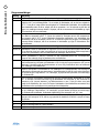 277
277
-
 278
278
-
 279
279
-
 280
280
-
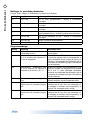 281
281
-
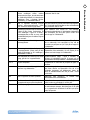 282
282
-
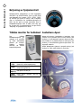 283
283
-
 284
284
-
 285
285
-
 286
286
-
 287
287
-
 288
288
-
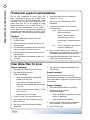 289
289
-
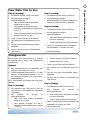 290
290
-
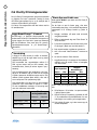 291
291
-
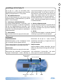 292
292
-
 293
293
-
 294
294
-
 295
295
-
 296
296
-
 297
297
-
 298
298
-
 299
299
-
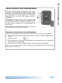 300
300
-
 301
301
-
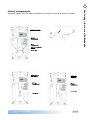 302
302
-
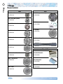 303
303
-
 304
304
-
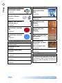 305
305
-
 306
306
-
 307
307
-
 308
308
-
 309
309
-
 310
310
-
 311
311
-
 312
312
-
 313
313


Cal Spas Portable Spas Bedienungsanleitung
- Typ
- Bedienungsanleitung
in anderen Sprachen
Verwandte Papiere
-
 Cal Spas Portable Spa Bedienungsanleitung
-
 Cal Spas Portable Spas Bedienungsanleitung
-
 Cal Spas Portable Spas Bedienungsanleitung
-
 Cal Spas Portable Spas Bedienungsanleitung
-
 Cal Spas Portable Spas Bedienungsanleitung
-
 Cal Spas Portable Spa Bedienungsanleitung
-
 Cal Spas Portable Spas Bedienungsanleitung
-
 Cal Spas Portable Spa Bedienungsanleitung


Sonstige Unterlagen
-
Bestway Lay-Z-Spa Bedienungsanleitung
-
-
Bestway 60059 Bedienungsanleitung
-
-
AVENLI SPA5 Benutzerhandbuch
-
EXIT Toys MSP-35101-V04 Benutzerhandbuch
-
AQUA FINESSE Spa Benutzerhandbuch
-
Balboa Circ Pump Benutzerhandbuch
-
 Pentair, Inc. INTELLIFLO VS-3050 Benutzerhandbuch
-
Riho whirlpool operation 4-key Installation and User Manual
