MyBinding Intimus S16.50 6 x 15 x 50 Industrial Cross Cut Shredder Benutzerhandbuch
- Kategorie
- Aktenvernichter
- Typ
- Benutzerhandbuch


15.90 S/16.50 S
(Seite 2-7)
(page 8-13)
(page 14-19)
(página 20-25)
(página 26-31)
(pagina 32-37)
(strona 38-43)
D
GB
F
E
P
I
PL
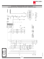
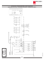
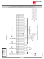
Schaltplan / Wiring Diagram / Plan de montage / Diagrama eléctrico /
Esquema electrico / Schema Elettrico / Schemat połączeń
(Seite / page / página /
pagina / strona: 44-46)
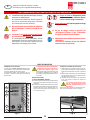
Vor der Inbetriebnahme die Betriebsanleitung durchlesen!
Before operating, please read the Operating Instructions!
Veuillez lire le mode d’emploi avant la mise en service!
Leer las instrucciones de uso antes de la puesta en servicio!
Antes de pôr a máquina em funcionamento leia as instruções de operação!
Prima della messa in funzione leggere attentamente le istruzioni!
Przed uruchomieniem urządzenia należy przeczytać instrukcję obsługi!
Betriebsanleitung
Operating instructions
Instructions d’opération
Instrucciones de uso
Instruções de Operação
Istruzioni per l’uso
Instrukcja obsługi
Typ/Type/Tipo/Típus:
655-12C + 655-8C + 655-6C
84236 9 01/13

22 20 21 171615
2524
18
23
19
2120
15.90 S/16.50 S
84236 9 01/13
D
Abb. 1
Abb. 2
Abb. 3 Abb. 4
2
Originalbetriebsanleitung

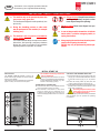
HINWEISE ZUM EINSATZORT:
Vergewissern Sie sich vor der Aufstellung, daß sich
am jeweiligen Einsatzort ein Drehstromanschluß
bendet (Angaben über die erforderliche Vorsi-
cherung der Netzsteckdose siehe „TECHNISCHE
DATEN“).
Hinweis: Beachten Sie die zulässige Flächenbe-
lastung des Bodens, da die Maschine ein Gesamt-
gewicht von ca. 726 kg erreichen kann.
Die Maschine darf nur entsprechend
dem vorgeschriebenen Verwendungs-
zweck eingesetzt werden!
Der Netzanschluß der Maschine muß
frei zugängig sein!
Die Maschine sollte nur in geschlos-
senen und temperierten (10-40 °C)
Räumen eingesetzt werden!
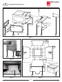
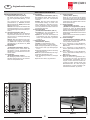
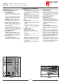
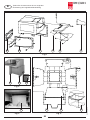
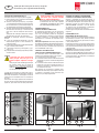
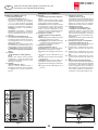
ZUSAMMENSTELLUNG
DER NUMERIERTEN TEILE:
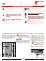
15 = Tisch (Abb. 1)
16 = Schutzwinkel links (Abb. 1)
17 = Schutzwinkel rechts (Abb. 1)
19 = Ausgleichschraube (Abb. 2)
20 = Rahmen links (Abb. 1)
21 = Rahmen rechts (Abb. 1)
22 = Zwischenblech (Abb.1)
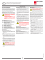
MONTAGE DES
UNTERGESTELLES (Abb. 1 und 2):
1. Das Zwischenblech (22) von den beiden
Rahmen (20+21) mit Hilfe des mitgelieferten
Spezialschlüssels abmontieren.
2. Die beiden Rahmen (20+21) vom Gehäuse
abmontieren.
3. Das komplette Aggregat hochheben und die
beiden Rahmen um 180 Grad gedreht (Rohr-
öffnungen nach unten) mit je 4 Schrauben
(M10x20) und Federringen wieder ans Gehäuse
montieren.
4. Das Zwischenblech (22) unterhalb des Tisches
zwischen die beiden Rahmen bringen und dort
mit jeweils 2 Schrauben (M10x20) und Feder-
ringen an den beiden Rahmen befestigen.
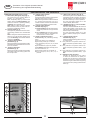
5. Das komplette Aggregat absetzen und die
noch offenen Bohrungen des Untergestelles
mit den mitgelieferten Kunststoffstopfen ver-
schließen.
Erst wenn alle Teile des Unterge-
stelles fest miteinander verschraubt
sind darf der Shredder abgesetzt
werden!
6. Unebenheiten des Bodens mit Hilfe der Aus-
gleichschrauben (19) ausgleichen (Abb. 2).
MONTAGE DES TISCHES (15) (Abb. 1):
1. Die Sechskantmuttern und Federringe an den
4 vorstehenden Schrauben an der Gehäuse-
Vorderwand abschrauben.
2. Den Tisch auf das Transportband legen
(Schraubenenden durch die Bohrungen des Ti-
sches), bis ans Gehäuse nach hinten schieben
und mit Hilfe der zuvor abgeschraubten Muttern
und Federringe an der Gehäuse-Vorderwand
befestigen.
3. Um den Tisch zu stabilisieren, müssen die unter
dem Tisch angebrachten 2 Sechskantschrau-
ben bis zum Anschlag nach oben herausge-
dreht und mit der jeweiligen Sechskantmutter
gekontert werden.
4. Das Stromkabel der Not-Aus-Leiste (14) durch
die Tülle vorne im linken Gehäuse-Seitenteil,
sowie durch die Kabelverschraubung unten
am Schaltkasten in den Schaltkasten führen
und dort die blaue Litze an Klemme 20 und
die braune Litze an Klemme 19 anschließen.
elektrischen Anschluß der Not-Aus-
MONTAGE DER SCHUTZWINKEL (Abb. 1):
Die beiden Schutzwinkel (16+17) mit Hilfe der
6 Flachkopfschrauben (M6x12) links und rechts
außen am Tisch (15) festschrauben.
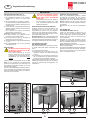
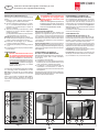
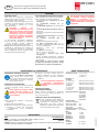
MONTAGE DER SCHALTKLAPPE (Abb. 3):
Die Schaltklappe (18) wird wie gezeigt an die am
Auslauf (hinter dem Schneidwerk) bendlichen
Klappenachse mit Hilfe der zwei dort befestigten
Schrauben angeschraubt.
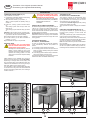
MONTAGE DES
AUFFANGBEHÄLTERS (23) (Abb. 4):
Es darf nur der mitgelieferte Original-
Auffangbehälter verwendet werden!
Die Verwendung anderer Behältnisse
ist aus Gründen der Zugriffsicherheit im
Bereich unterhalb der Maschine nicht
zulässig.
Hinweis: Die Rückwand, sowie die beiden
Seitenwände und der Fußrahmen werden mit
Hilfe der mitgelieferten Verbindungsbolzen und
der Verschlußeinsätze zusammenmontiert. Der
Bolzen wird durch das anzuschraubende Teil
gesteckt und so dem im anderen Teil bendlichen
Verschlußeinsatz zugeführt. Durch Drehen des
Verschlußeinsatzes im Uhrzeigersinn (Pfeilrich-
tung) wird der Bolzen dort verriegelt.
Gehen Sie nun beim Zusammenbau des Auffang-
behälters wie folgt vor:
1. Rückwand mit Fußrahmen montieren.
2. Seitenwände (hellere Seite nach innen) mit
Fußrahmen und mit Rückwand montieren.
3. Vorderwand (25) mit Hilfe der mitgelieferten
Scharnierbolzen an Fußrahmen montieren
(Scharnierbolzen von außen in die Scharniere
stecken).
4. Gelenkbolzen für Bügel wie gezeigt durch die
Seitenwände stecken und den Bügel (24) von
vorne zu den Bohrungen der rausstehenden
Gelenkbolzen-Enden führen, durchstecken
und dort mit Hilfe der beiden Gewindestifte
festschrauben.
5. Puffer wie gezeigt an Vorderwand montieren.
6. Bodenplatte einlegen, Vorderwand hochklap-
pen und mit Bügel sichern.
7. Plastiksack einlegen und das Ende über den
Rand nach außen stülpen.
15.90 S/16.50 S
84236 9 01/13
AUFSTELLUNG
D
3
Originalbetriebsanleitung

EINSATZBEREICH:
Der Datenshredder 15.90 S / 16.50 S ist eine
Maschine zum Zerkleinern großer Mengen all-
gemeinen Schriftgutes.
Der Shredder zerkleinert Kartonagen und Knüllpa-
pier genauso mühelos wie glattes Papier.
Die Maschine darf nur zur Zerklei-
nerung von Papier oder Kartonagen
verwendet werden!
Die Zerkleinerung andersartiger Daten-
träger kann Verletzungen an der Person
(z.B. durch Splitterung fester Materialien
etc.), sowie Schäden am Gerät (z.B.
Zerstörung des Schneidwerkes etc.) zur
Folge haben.
HINWEISE ZUM NETZANSCHLUSS:
a) Der Schleifenwiderstand der Netzversorgung
am Anschlußort darf höchstens 0,5 Ohm be-
tragen.
b) Der Leitungsquerschnitt der Stromzuführung
am Anschlußort muß so dimensioniert sein,
daß bei blockierter Maschine die Spannung um
max. 15% absinkt (Blockierstrom der Maschine
= 6 x Nennstrom).
ÜBERPRÜFUNG DER LAUFRICHTUNG:
1. Not-Aus-Leiste (14) (Abb. 6) am Shredder-
Tisch entriegeln (Leiste herausziehen) und
Hauptschalter (1) einschalten (Stellung „1“).
2. Verriegelungsschalter (2) entriegeln und Druck-
taster „Vorwärtslauf Schneidwerk“ (3) (Abb. 5)
betätigen.
3. Die Laufrichtung des Shredders überprüfen
und ggf. durch Phasentausch am Netzstecker
richtigstellen.
Die Arbeit des Phasentausches
am Netzstecker darf nur von einem
Wenn alles fachgerecht aufgestellt und ange-
schlossen ist, kann die Inbetriebnahme erfol-
gen.
WICHTIGE SICHERHEITSHINWEISE
<< Verletzungsgefahr! Lose Teile von Beklei-
dung, Krawatten, Schmuck, langes Haar,
Einlaßöffnung fernhalten!
<< Verletzungsgefahr! Nicht mit den Fingern in die
Einlaßöffnung fassen!
<< Im Gefahrenfalle die Maschine am Hauptschalter,
oder Not-Aus-Schalter ausschalten, oder den
Netzstecker ziehen!
<< Vor dem Öffnen der Maschine ist der Netzstecker
zu ziehen!
Reparaturen dürfen nur von einem Fachmann
durchgeführt werden!
nicht von mehreren Personen
gleichzeitig bedient werden!
Die Auslegung der Sicherheitselemente beruhen auf
einer gefahrlosen Bedienung im “Einmannbetrieb“.
keine andere Arbeiten (z. B. Reinigung etc.) an
<< Die Maschine ist kein Spielzeug und für Einsatz
und Benutzung durch Kinder nicht geeignet!
Die sicherheitstechnische Gesamtkonzeption (Abmes-
sungen, Zuführöffnungen, Sicherheitsabschaltungen
etc.) dieser Maschine beinhaltet keine Garantie einer
gefahrlosen Handhabung durch Kinder.
15.90 S/16.50 S
14
6
13
12
11
10
9
8
7
1
2
3
4
5
84236 9 01/13
INBETRIEBNAHME
D
Abb. 5
4
Abb. 6
Originalbetriebsanleitung

15.90 S/16.50 S
14
6
13
12
11
10
9
8
7
1
2
3
4
5
84236 9 01/13
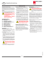
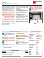
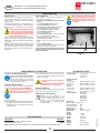
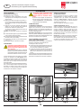
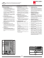
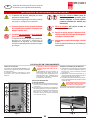
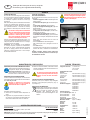
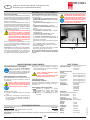
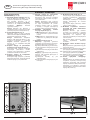
BEDIENUNGSELEMENTE (Abb. 5, 6):
1 = Hauptschalter (Not-Aus) (Abb. 5)
Mit diesem Schalter wird die Maschine
ein- bzw. ausgeschaltet (Stellung „1“, bzw.
„0“).
Das Lämpchen der Kontroll-Anzeige
„Betriebsbereit“ (7) leuchtet (korrekter
Betriebszustand) bzw. blinkt (nicht korrekter
Betriebszustand) auf.
Hinweis: Das Lämpchen leuchtet erst nach
einer Zeitverzögerung von ca. 2 Sekunden
auf (Initialisierungsroutine für den Mikropro-
zessor).
2 = Verriegelungsschalter (Abb. 5)
Mit diesem Schalter kann die Maschine
abgeschlossen (Schlüssel nach links dre-
hen) und somit vor unbefugter Benutzung
gesichert werden.
Hinweis: Wird die Maschine bei einge-
schaltetem Hauptschalter (1) abgeschlos-
sen, blinkt das Lämpchen der Anzeige
„Betriebsbereit“ (7) als Zeichen für
3 = Drucktaster
Bei Betätigung dieses Tasters laufen das
Schneidwerk und das Transportband des
Shredders an und die Maschine kann be-
schickt werden.
4 = Drucktaster
Bei Betätigung dieses Tasters wird der
Shredder abgeschaltet und das Schneid-
werk mit Transportband steht.
BEDIENUNGSELEMENTE
5 = Drucktaster
Bei Betätigung dieses Tasters laufen das
Schneidwerk, sowie das Transportband
rückwärts.
Hinweis: Wird der Taster während des
Vorwärtslaufes betätigt, so werden nach
einem mindestens 3 Sekunden lang dau-
ernden Rückwärtslauf das Schneidwerk
mit Transportband automatisch wieder auf
Vorwärtslauf geschaltet.
6 = Kontroll-Anzeige
a) Leuchtet auf, wenn Schneidwerk und
Transportband vorwärts laufen.
b) Blinkt auf, wenn das Schneidwerk mit
Transportband aus dem Vorwärtslauf
heraus auf Rückwärtslauf geschaltet
worden ist.
7 = Kontroll-Anzeige
Leuchtet auf (betriebsbereit), wenn
a) der Hauptschalter (1) eingeschaltet,
b) der Verriegelungsschalter (2) entriegelt,
c) die Not-Aus-Leiste (14) herausgezogen
ist und
d) der Auffangbehälter (23) bis zum Anschlag
untergeschoben ist.
Blinkt auf (nicht betriebsbereit) bei einge-
schaltetem Hauptschalter, wenn
a) der Verriegelungsschalter (2) verriegelt
ist, oder
b) die Not-Aus-Leiste (14) gedrückt ist.
8 = Kontroll-Anzeige
Blinkt auf, wenn der Motor des Shredders
überfordert worden ist und der eingebaute
Thermoschutz den Stromkreis für Vollbetrieb
unterbrochen hat. Näheres siehe unter der
Rubrik „Motorstörung“
9 = Kontroll-Anzeige
Leuchtet auf, wenn der Auffangbehälter
gefüllt ist und geleert werden muß, oder der
Behälter nicht vollständig eingeschoben ist..
Gleichzeitig wird die Maschine automatisch
abgeschaltet.
Näheres siehe unter der Rubrik „Entleeren
des Auffangbehälters“
10 = Kontroll-Anzeige
Leuchtet auf, wenn das Schneidwerk mit
Transportband rückwärts läuft.
11 = nur in Verbindung mit dem Wertstoffver-
dichter (hydraulische Ballenpresse) Typ
860 relevant.
12 = nur in Verbindung mit dem Wertstoffver-
dichter (hydraulische Ballenpresse) Typ
860 relevant.
13 = nur in Verbindung mit dem Wertstoffver-
dichter (hydraulische Ballenpresse) Typ
860 relevant.
14 = Not-Aus-Leiste (Abb. 6)
Wenn es einmal aus irgendeinem Grun-
de notwendig sein sollte, die Maschine
schnellstmöglich auszuschalten bzw. zu
stoppen, so kann dies durch Drücken die-
ser Not-Aus-Leiste erreicht werden. Zum
Wiedereinschalten die Leiste entriegeln
(herausziehen) und den Drucktaster „Vor-
wärtslauf Schneidwerk“ (3) drücken.
D
Abb. 5
5
Abb. 6
Originalbetriebsanleitung

EINSATZ DER MASCHINE (Abb. 5):
Zum Einschalten gehen Sie wie folgt vor:
1. Den beigefügten Schlüssel in den Verriege-
lungsschalter (2) stecken und nach rechts
drehen.
2. Den Hauptschalter (1) in Stellung „1“ stellen.
Das Lämpchen der Anzeige „Betriebsbereit“ (7)
leuchtet nach einer zeitlichen Verzögerung von
2 Sekunden auf.
3. Den Drucktaster „Vorwärtslauf Schneidwerk“ (3)
betätigen. Das Schneidwerk mit Transportband
werden gestartet.
Das Lämpchen der Anzeige „Vorwärtslauf
Schneidwerk“ (6) leuchtet auf.
Achtung: Die Maschine läuft nur, wenn
a) die Not-Aus-Leiste (14) entriegelt ist (rote
Schiene am Tisch herausziehen),
b) der Verriegelungsschalter (2) entriegelt ist
(Schlüssel nach rechts drehen),
c) der Hauptschalter (1) eingeschaltet ist (Stellung
„1“) und
d) der Auffangbehälter (23) bis zum Anschlag
untergeschoben ist.
BESCHICKUNG:
Der Bediener darf bei der Beschickung
der Maschine nicht höher als die Ma-
schine selbst stehen!
Paletten, Kisten etc.) vor der Maschine
ist bezüglich der erforderlichen Sicher-
heitsabstände zum Schneidwerk nicht
zulässig.
Glattes Papier wird stapelweise bis zu ca. 550
Blatt (je nach Ausführung und Papiersorte)
genauso wie Knüll-Papier und Kartonagen auf
das laufende Transportband gelegt und so dem
Schneidwerk zugeführt.
Um eine schlagartige Belastung des Schneidwer-
kes zu vermeiden, ist es jedoch gut, wenn Sie den
Stapel aus glattem Papier schräg, das heißt mit
einem Eck voraus zuführen.
mehr als die angegebene Höchst-
Sollte trotzdem einmal zuviel Papier in
das Schneidwerk gelangt sein, siehe
BESCHICKUNG KOMPLETTER ORDNER:
Shredder, welche mit einem Schneidwerk der
Schnittbreite 7,8 x 55 mm oder 11,8 x 55 mm
ausgestattet sind, können auch mit kompletten
Ordnern (einschl. Mechanik) beschickt werden.
Der Ordner sollte hierbei aufgeschlagen und der
Inhalt gleichmäßig verteilt sein.
Wichtiger Hinweis: Das vorherige Entfernen der
Metallteile (Mechanik) ermöglicht eine Wiederver-
wertung (Recycling) des Schnittgutes und sorgt für
eine längere Lebensdauer des Schneidwerks.
AUTOMATIK-SCHALTUNG
Sollte der Shredder einmal „überfüttert“ werden,
so „regelt“ dieser alles weitere automatisch wie
folgt:
1. Das Schneidwerk blockiert.
2. Schneidwerk mit Transportband laufen ein
Stückweit rückwärts. Das Zerkleinerungsgut
wird frei.
3. Schneidwerk mit Transportband schalten wie-
der auf Vorwärtslauf. Das Zerkleinerungsgut
wird erneut dem Schneidwerk zugeführt.
Dieser Bewegungsablauf wird von der Maschine
selbständig so lange wiederholt, bis das Zerklei-
nerungsgut rückstandslos durchgelaufen und
zerkleinert ist.
ÜBERFÜLL-STOPPAUTOMATIK:
Wenn der Auffangbehälter gefüllt ist, schaltet
die Maschine automatisch ab. Zum Zeichen
dafür leuchtet das Lämpchen der Anzeige „Auf-
fangbehälter voll“ (9) auf. Gleichzeitig ertönt ein
Hupton. Quittieren Sie den Hupton, indem Sie
einmal kurz den Drucktaster „Stopp Schneidwerk“
(4) betätigen.
Entleeren Sie nun wie folgt den Auffangbehäl-
ter.
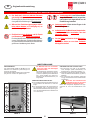
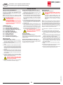
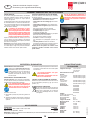
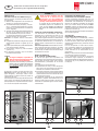
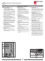
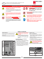
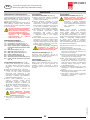
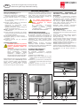
ENTLEEREN DES
AUFFANGBEHÄLTERS (Abb. 8):
Fassen Sie den Behälter am Bügel (24) und
ziehen ihn unter dem Shredder hervor. Heben
Sie den Bügel hoch, klappen die Behälter-Vor-
derwand (25) nach unten und entnehmen den
vollen Plastiksack.
Nachdem ein neuer Sack eingesetzt und der
Behälter mit hochgeklappter Vorderwand wieder
unter den Shredder geschoben ist, können Sie
mit der Zerkleinerung fortfahren.
Hinweis: Die Maschine läuft nur bei untergescho-
benem Auffangbehälter!
Zum Zeichen des nicht eingeschobenen Behälters
leuchtet das Lämpchen der Anzeige „Auffangbe-
hälter nicht eingeschoben“ (9) und die Maschine
kann nicht gestartet werden.
15.90 S/16.50 S
25
24
24 25
23
14
6
13
12
11
10
9
8
7
1
2
3
4
5
84236 9 01/13
BEDIENUNG
D
Abb. 5 Abb. 7
Abb. 6
Abb. 8
6
Originalbetriebsanleitung

3. Seitenabdeckung anmontieren und den Netz-
stecker einstecken. Die Maschine kann wieder
in Betrieb genommen werden.
-
rungen vorgenommen werden!
Bei Nichtbeachtung erlischt die Be-
triebserlaubnis!
TIP ZUR ENERGIEEINSPARUNG:
Achten Sie darauf, daß die Maschine über Nacht
ausgeschaltet ist (Hauptschalter (1) (Abb. 5) in
Stellung „0“).
ENTSORGUNG DER MASCHINE:
Entsorgen Sie die Maschine am Ende
ihrer Lebensdauer stets umweltgerecht.
Geben Sie keine Teile der Maschine oder
der Verpackung in den Hausmüll.
WARTUNG SCHNEIDWERK:
Nach ca. 8 Stunden Dauerbetrieb für ca.
30 Sekunden auf Rückwärtslauf schalten
und gleichzeitig etwas von dem mitgelie-
ferten Spezial-Öl auf das Schneidwerk
sprühen.
WARTUNG GETRIEBE:
Monatlich müssen die beiden Synchronräder,
sowie die Kettenräder und die Antriebskette
nachgefettet werden.
Vor dem Öffnen der Maschine ist die
auszuschalten und der Netzstecker
zu ziehen!
Gehen Sie wie folgt vor:
1. Linke Seitenabdeckung am Gehäuse abmon-
tieren.
2. Die oben beschriebenen Teile mit Hilfe eines
Pinsels, oder einer Fettpresse mit einem han-
delsüblichen Schmierfett einfetten.
MOTORSTÖRUNG:
Wird der Motor des Shredders einmal überfordert,
so unterbricht ein eingebauter Thermoschutz den
Stromkreis für Vollbetrieb. Das Lämpchen der
Anzeige „Störung Motor“ (8) blinkt auf.
Der Shredder kann jedoch während der Abkühl-
phase des überforderten Motors im Tastbetrieb
(Shredder mit reduzierter Leistung - Sternschal-
tung) weitergefahren werden (z. B. zur Rückfüh-
rung von Schnittgut etc.).
Der Einsatz des Shredders mit redu-
zierter Leistung darf nur zur Entnahme
des Zerkleinerungsgutes, oder zur
-
weiterter Einsatz in dieser Phase kann
Nach erfolgter Abkühlung (ca. 5-10 Min.) erlischt
das Lämpchen und die Maschine kann wieder
im Vollbetrieb (Dreieckschaltung) eingesetzt
werden.
Hinweis: Sollte die Maschine trotz erfolgter
Abkühlung des überforderten Motors nicht mehr
im Vollbetrieb arbeiten (Lämpchen (8) erlischt
nicht), so handelt es sich um einen Defekt in der
Maschine. Benachrichtigen Sie in diesem Fall
bitte unseren Kundendienst.
CHECKLISTE BEI STÖRUNGEN:
Sollte die Anlage nicht funktionieren, prüfen Sie
folgende Punkte:
- ist der Netzanschlußstecker des Shredders
am Netz angeschlossen?
- ist der Verriegelungsschalter (2) entriegelt?
- ist der Hauptschalter (1) eingeschaltet?
- ist die Not-Aus-Leiste (14) entriegelt?
Rote Schiene am Tisch herausziehen.
- ist der vollständig unter-
geschoben?
- ist der voll?
Der Behälter muß geleert werden.
- ist die Schaltklappe (18) (Abb. 3) für die „Auf-
fangbehälter voll“-Anzeige frei beweglich?
Muß im Bedarfsfalle gängig gemacht werden.
- ist der Motor überlastet worden?
Siehe Beschreibung unter „Motorstörung“
- ist eine Phase ausgefallen?
Überprüfen Sie die drei Phasen-Sicherungen
an der Netzsteckdose und wechseln Sie sie
gegebenenfalls aus.
Wenn keine der Prüfpunkte zutreffen, benach-
richtigen Sie bitte unseren Kundendienst.
Öffnen der Anlage der Netzstecker
zu ziehen, sowie der Hauptschalter
auszuschalten und mit einem Vorhän-
15.90 S/16.50 S
18
84236 9 01/13
STÖRUNG
WARTUNG / ENTSORGUNG TECHNISCHE DATEN
Schnittbreiten: 11,8 x 55 mm
7,8 x 55 mm
6 x 50 mm
Schneidleistung:
15.90 S:
11,8 x 55 mm: 260-320 Blatt (70 g/m
2
)
7,8 x 55 mm: 200-260 Blatt (70 g/m
2
)
6 x 50 mm: 180-210 Blatt (70 g/m
2
)
16.50 S:
11,8 x 55 mm: 400-550 Blatt (70 g/m
2
)
7,8 x 55 mm: 350-420 Blatt (70 g/m
2
)
6 x 50 mm: 300-330 Blatt (70 g/m
2
)
Anschlußspannung: 400V/50Hz
230V/50Hz
415V/50Hz
220V/60Hz
200V/50Hz
200V/60Hz
Vorsicherung:
(Sicherung gl, Zuordnungsart 1)
400V-415V/50Hz: 35 A
220V-230V/50Hz: 40 A
200V/50Hz: 63 A
Arbeitsbreite: 500 mm
ca. 74 dB(A)
Leistung:
15.90 S: 5,5 kW
16.50 S: 7,5 kW
1950 mm
Breite: 1200 mm
Höhe: 1550 mm
Gewicht:
15.90 S: ca. 696 kg
16.50 S: ca. 726 kg
SONDERZUBEHÖR
Benennung Best.-Nr.
Plastiksack, 900 x 900 x 1500 x 0,15 mm 99960
Öläschchen, 125 ml 99943
HInweis: Bei Nachbestellung von Sonderzubehörteilen und bei Ersatzteilbedarf wenden
Sie sich bitte an Ihren Fachhändler.
D
7
Abb. 3
Originalbetriebsanleitung

Fig. 4
22 20 21 171615
Fig. 3
2524
Fig. 1
18
23
Fig. 2
19
2120
15.90 S/16.50 S
84236 9 01/13
GB
8
Translation of the Original Operation Manual
Übersetzung der Originalbetriebsanleitung

INSTALLATION REQUIREMENTS:
Be certain that three phase current is available at
the point of installation (see TECHNICAL DATA
for information concerning required pre-fusing of
the electrical outlet).
Note: Since this machine can weigh up to 726
kg, it is essential to check the permissible load
per square meter of the oor.
The machine may only be used for its
intended purpose!
The machine’s mains connection must
be freely accessible!
The machine should only be operated
in closed rooms within a temperature
range of 10 to 40° C!
NUMBERED PARTS:
INSTALLING THE
BASE FRAMES (Figs. 1 and 2):
1. Remove the dividing panel (22) from between
the two frames (20+21), using the special
purpose spanners provided.
2. Remove both frames (20+21) from the housing
case.
3. Lift the complete unit and rotate the two frames
by 180° so that the open ends of the frame are
facing downwards. Re-attach the frames to the
housing using four screws (M 10x20) and lock
washers.
4. Place the dividing panel (22) beneath the feed
table between the two frames. Attach the plate
to the frames using two screws (M 10x20) and
lock washers.
5. Lower the complete unit and use the plastic
stoppers supplied to seal off the remaining
open holes on the base frame.
Ensure all parts of the base frame
lowering the shredder!
6. Adjust the levelling screws (19) to compensate
for any unevenness in the oor (g. 2).
INSTALLING THE FEED TABLE (15) (Fig. 1):
1. Remove the hexagonal nuts and the lock
washers from the 4 projecting screws on the
front panel of the housing.
2. Place the feed table on the conveyor belt so
that the ends of the screws go through the holes
on the feed table. Push the table up against
the housing and attach it to the front panel
using the nuts and washers you have already
removed.
3. To ensure that the feed table is secure, unscrew
the two hexagonal screws under the feed table
as far as possible, and secure each with a
hexagonal nut.
4. Guide the power cable for the emergency-stop
rail (14) through the sleeve on the front side
of the housing, through the cable gland on the
bottom of the switch box, and on into the switch
box. Then connect the blue wire to terminal 20
and the brown wire to terminal 19.
The emergency-stop rail detailed
under point 4 must be installed by
INSTALLING THE
PROTECTIVE ANGLES (Fig. 1):
Secure the two protective angles (16+17) to the
right and left of the feed table (15) using the 6 at
headed screws.
INSTALLING THE SWITCH FLAP (Fig. 3):
Screw the switch ap (18) to the hinge located
at the outlet (behind the cutter), using the two
available screws, as illustrated.
INSTALLING THE
SHREDDER BIN (23) (Fig. 4):
Only the original shredder bin which
was delivered with the machine may
be used!
permitted because this might allow the
operator to reach into the underside of
the machine and represents a safety
hazard.
Note: The connecting bolts and locking elements
used to connect the back panel, the two side pa-
nels, and the base frame are included in delivery.
Insert the bolt through the panel you wish to connect
and match it to the locking element on the other
part. Turning the locking element clockwise (in the
direction of the arrow) secures the bolt.
To assemble the shredder bin proceed as fol-
lows:
1. Connect the back panel to the base frame.
2. Connect the side panels (lighter shaded side
facing inwards) to the base frame and back
panel.
3. Connect the front panel (25) to the base frame
using the hinge bolts supplied (insert the hinge
bolts into the hinges from the outside).
4. Insert the stirrup hinge bolts through the side
panels, as illustrated. Then, place the ends of
the stirrup (24) through the holes in the hinge
bolts, and nally, secure the stirrup using the
two locking screws.
5. Attach the buffers to the front panel, as illust-
rated.
6. Insert the base plate, bring up the front panel
and secure in place with the stirrup.
7. Now you can place a plastic bag in the bin and
fold the end of the bag over the bin rim.
15.90 S/16.50 S
84236 9 01/13
INSTALLATION
GB
9
Translation of the Original Operation Manual
Übersetzung der Originalbetriebsanleitung

The shredder should only be fed with
paper or cardboard!
Shredding other data carriers can cause
injury(e.g. by splintering of hard materials)
or may damage the shredder (e.g. des-
truction of the cutting system).
POWER SUPPLY CONNECTION:
a) The maximum value for loop impedance at the
mains connection point is 0.5 Ohms.
b) The conductor cross-section of the power
supply line should be of a magnitude so as
to cause a 15% voltage drop in the case of a
machine blockage (inhibit current = 6 x nominal
current).
APPLICATION:
The 15.90 S / 16.50 S shredder is used in all
areas where large quantities of printed material
need to be shredded.
The machine can shred cardboard and crumpled
paper as easily as it shreds smooth paper.
CHECKING THE RUNNING DIRECTION:
1. Free the emergency-stop rail (pull out the rail)
(14) (g. 6) on the shredder feed table. Switch
on the main switch (1) (g. 5); i.e. to position
„1“.
2. Unlock the locking switch (2) and press the
„cutting system forward“ button(3) (g. 5).
3. Check that the shredder is running in the correct
direction and correct the phase relation of the
power plug if necessary.
Correcting the phase relation of the
power plug may only be carried out
Now that everything has been correctly assembled
and connected, you can proceed to operating
the machine.
IMPORTANT SAFETY PRECAUTIONS
<< Danger of injury! Keep all loose articles of
clothing, ties, jewelery, long hair or other
loose objects away from opening!
<< Danger of injury!-
ning!
<< In case of danger switch the machine off with the
mains switch, or with the emergency switch, or
unplug the machine!
<< Always unplug the machine from the mains power
supply before opening the machine!
Repairs may only be performed by trained per-
sonnel!
<< The machine may not be operated by more than
one person at any given time!
The machine was designed for safe operation by “one
person only”.
<< During the shredding process no other work
may be performed on the machine (for example
cleaning, etc.)!
<< The machine is not a toy, and is not suitable for
use by children!
The overall technical safety concept of this machine
(dimensions, feed openings, emergency shutdown
devices etc.) does not provide for any guarantee
regarding hazard-free operation by children.
15.90 S/16.50 S
Fig. 6
14
Fig. 5
6
13
12
11
10
9
8
7
1
2
3
4
5
84236 9 01/13
INITIAL START UP
GB
10
Translation of the Original Operation Manual
Übersetzung der Originalbetriebsanleitung

15.90 S/16.50 S
Fig. 6
14
Fig. 5
6
13
12
11
10
9
8
7
1
2
3
4
5
84236 9 01/13
OPERATING FUNCTIONS (Figs. 5 and 6):
This switch turns the machine either on
(position „1“) or off (position „0“).
When the „Ready“ lamp (7) on the control
display remains on without blinking, this
means the machine is operating correctly.
A blinking lamp indicates a fault.
Note: There is a delay of about 2 seconds
before the lamp comes on (due to the mic-
roprocessor initialization routine).
Turning the key to the left locks the machi-
ne providing protection from unauthorized
use.
Note: Locking the machine when the main
switch (1) is on will cause the „Ready“ lamp
(7) to start blinking. This indicates that the
machine is not Ready.
Pressing this button starts the cutting system
and the conveyor belt. Material can now be
fed to the shredder.
Pressing this button switches the shredder
off, thereby halting the cutting system and
the conveyor belt.
EXPLANATION OF THE CONTROLS
Pressing this button starts the cutting system
and the conveyor belt in reverse.
Note: Pressing this button while the machine
is in forward mode will cause it to run in
reverse mode for at least 3 seconds before
returning automatically to forward mode.
a) Continuously lit when the cutting system
and conveyor belt are running in forward
mode.
b) Starts blinking when the cutting system
and conveyor belt are switched from
forward mode to reverse mode.
Continuously lit (indicating Ready)
when:
a) the main switch (1) is switched on,
b) the locking switch (2) is unlocked,
c) the emergency-stop rail (14) is pulled
out, and
d) the shredder bin (23) is fully docked.
Starts blinking (indicating not ready) when
the main switch is on, if:
a) the locking switch (2) is engaged, or
b) the emergency-stop rail (14) is
pressed.
Starts blinking when the shredder motor is
overloaded, thereby activating the built-in
thermal protection. This leads to a break in
the circuit necessary for active operation.
For more information please turn to the
section headed „Motor Fault“.
Comes on when the Shredder bin is full and
needs to be emptied, or when the bin is not
fully docked. When this lamp comes on the
machine stops automatically.
For more information please turn to the
section headed „Emptying the shredder
bin“.
Comes on when the cutting system is running
in reverse mode.
11 = Only relevant in conjunction with the ma-
terials compactor (hydraulic bailer) - Type
860.
12 = Only relevant in conjunction with the ma-
terials compactor (hydraulic bailer) - Type
860.
13 = Only relevant in conjunction with the ma-
terials compactor (hydraulic bailer) - Type
860.
Should it be necessary for any reason
to switch the machine off as quickly as
possible, this can be done by pressing the
emergency-stop rail. In order to switch the
machine on again: release the rail by pulling
it out and push the „cutting system forward“
button (3).
GB
11
Translation of the Original Operation Manual
Übersetzung der Originalbetriebsanleitung

OPERATING THE MACHINE (Fig. 5):
The procedure is as follows:
1. Insert the key (included in delivery) in the locking
switch (2) and turn to the right.
2. Move the main switch (1) to position „1“.
After a 2 second pause the „Ready“ lamp (7)
comes on.
3. Press the „Cutting system forward“ button
(3).
The cutting system and conveyor belt now
begin to run.
The „cutting sysytem forward“ lamp (6) comes
on.
Attention: The machine will only operate when
a) the emergency-stop rail (14) has been released
(pull out the red rail on the feed table),
b) the locking switch (2) has been released,
c) the main switch (1) has been switched on
(position „1“), and
d) the shredder bin (23) is fully docked.
MATERIAL FEED:
The operator may not stand higher
than the machine itself stands, when
feeding paper to the machine!
Standing on an raised platform (such as
pallets or boxes placed in front of the
machine) reduces the distance between
operator and cutting system to a level
which does not meet the required safety
standard.
Feed material for the shredder can consist of
stacks of smooth paper (up to about 550 sheets,
depending on the type and size of paper); and
also crumpled paper and cardboard. Place any
material to be shredded on the moving conveyor
belt which feeds it to the cutting system.
It is advisable to place stacked paper diagonally
on the belt. In this way, the corner of the stack will
be fed to the cutting system rst, thus avoiding a
sudden overload.
Never feed the shredder with a quan-
tity of paper exceeding the maximum
indicated in the technical data!
Should the machine become overloaded,
-
FEEDING WITH COMPLETE BINDERS!
Shredders equipped with a cutting system with 7.8
x 55 mm or 11.8 x 55 mm cutting width, can also
be fed with complete binders (incl. metal parts).
In this case the binder should be opened and the
contents spread out equally.
Important note: The removing of the metal parts
beforehand makes the recycling of the shredded
material possible and ensures a longer life of the
cutting system.
AUTOMATIC RESPONSE
In case you accidentally overload the shredder,
it will automatically alleviate the problem as
follows:
1. The cutting system becomes jammed.
2. The cutting system and the conveyor belt run
briey in reverse, thereby freeing the material
to be shredded.
3. The cutting system and the conveyor automati-
cally switch back to forward mode.
The machine repeats this process until the all the
material has been shredded satisfactorily.
AUTOMATIC STOP
IN CASE OF FULL SHREDDER BIN:
The machine switches off automatically when
the shredder bin becomes full. This is indicated
by the „Shredder bin full“ lamp (9) and is also
accompanied by an acoustic signal.
To switch off the acoustic signal, push the „Cutting
system stop“ button (4) briey.
Then proceed as follows to empty the shredder
bin.
EMPTYING THE SHREDDER BIN (Fig. 8):
To empty the shredder bin, grip the bin (23) by
the stirrup (24), pulling it out from under the
shredder.
Then, pull up the stirrup, open out the front panel,
(25) and remove the full plastic sack.
After placing a new sack in the bin, close the front
panel and push the bin back under the shredder.
You are now ready to resume shredding.
Note: The machine will only function if the shredder
bin is in place.
When the shredder bin is not in place, the „Shred-
der bin not in place“ indicator lamp (9) comes on,
indicating that the shredder cannot be operated.
15.90 S/16.50 S
Fig. 8
25
Fig. 7
24
24 25
23
Fig. 6
14
Fig. 5
6
13
12
11
10
9
8
7
1
2
3
4
5
84236 9 01/13
OPERATION
GB
12
Translation of the Original Operation Manual
Übersetzung der Originalbetriebsanleitung

3. Re-install the side cover and connect the ma-
chine to the mains. The machine can be put
back into operation.
any way!
Operation of the machine is prohibited
ENERGY SAVING TIP:
Be certain that the machine is turned off overnight
(main switch (1) (g. 5) switched to „0“).
DISPOSING OF THE MACHINE:
Dispose of the machine in an
environmentally sound fashion at the
end of its useful service life. Do not
dispose of any of the parts included
in the machine or its packaging with
household trash.
MOTOR FAULT:
If the motor is overloaded, the integrated ther-
mal protection system cuts off the main power
supply. This is indicated by the blinking „Motor
fault“ lamp (8).
However, while the motor is cooling down, you
can still operate the machine in inching mode (at
reduced power - Y-connection; e.g. to retrieve
material).
The shredder should only be operated
at reduced power to retrieve material
or to fully shred material already being
After the machine has cooled down sufciently
(about 5-10 minutes), the lamp goes out, and the
machine can again be operated normally (delta
connection).
Note: If the machine still does not return to normal
operation after cooling down (lamp (8) fails to go
out), this means there is a fault in the machine.
If this occurs, please notify our customer service
department.
FAULT CHECKLIST:
If the machine is not functioning properly, you
should check the following:
- is the machine plugged into the mains power
supply?
- is the locking switch (2) unlocked?
- is the main switch (1) turned on?
- is the emergency-stop rail (14) released?
Pull out the red rail on the feed table.
- is the shredder bin (23) fully docked?
- is the shredder bin (23) full?
Empty the shredder bin.
- is the (g. 3) for the „shredder
bin full“ indicator easy to move?
It may be necessary to free the switch.
- is the motor overloaded?
Please refer to the section headed „Motor
Fault“.
- is there a phase failure?
Check the three-phase fuse at the power supply
socket, and replace if necessary.
If you still cannot isolate the fault after carrying
out all these checks, please notify our customer
service department.
Always unplug the machine from the
mains power supply, turn off the main
switch and lock it with a padlock be-
fore opening the machine to carry out
CUTTING SYSTEM MAINTANANCE:
After about 8 hours of continuous ope-
ration run the cutting system in reverse
for about 30 seconds and, at the same
time, spray some of the enclosed special
oil onto the cutting system.
GEAR BOX MAINTAINANCE:
Both synchron gears, as well as the chain wheels
and drive chains must be greased monthly.
The machine must be turned off at the
Proceed as follows:
1. Remove the left side cover from the housing.
2. Grease the above mentioned parts with a brush
or a grease gun, and a standard, commercially
available grease.
15.90 S/16.50 S
Fig. 3
18
84236 9 01/13
MALFUNCTION
Description Order-No.
Plastic bag, 900 x 900 x 1500 x 0,15mm 99960
Lubrication bottle, 125 ml 99943
Note: Please contact your dealer when ordering accessories and replacement parts.
ACCESSORIES
TECHNICAL DATA
Cutting widths: 11.8 x 55 mm
7.8 x 55 mm
6 x 50 mm
Cutting capacity:
15.90 S:
11.8 x 55 mm: 260-320 sheets (70 g/m
2
)
7.8 x 55 mm: 200-260 sheets (70 g/m
2
)
6 x 50 mm: 180-210 sheets (70 g/m
2
)
16.50 S:
11.8 x 55 mm: 400-550 sheets (70 g/m
2
)
7.8 x 55 mm: 350-420 sheets (70 g/m
2
)
6 x 50 mm: 300-330 sheets (70 g/m
2
)
Supply voltage: 400V/50Hz
230V/50Hz
415V/50Hz
220V/60Hz
200V/50Hz
200V/60Hz
Pre-fusing:
(gl fuse, type 1 assignment)
400V-415V/50Hz: 35 A
220V-230V/50Hz: 40 A
200V/50Hz: 63 A
Working width: 500 mm
Noise level: approx. 74 dB(A)
Power:
15.90 S: 5.5 kW
16.50 S: 7.5 kW
Length: 1950 mm
Width: 1200 mm
Height: 1550 mm
Weight:
15.90 S: approx. 696 kg
16.50 S: approx. 726 kg
MAINTENANCE / DISPOSING
GB
13
Translation of the Original Operation Manual
Übersetzung der Originalbetriebsanleitung

Fig. 4
22 20 21 171615
Fig. 3
2524
Fig. 1
18
23
Fig. 2
19
2120
15.90 S/16.50 S
84236 9 01/13
F
14
Traduction de Mode d'emploi d‘origine
Übersetzung der Originalbetriebsanleitung

REMARQUE SUR LE LIEU D’INSTALLATION:
Avant l’installation de la machine, veuillez vous
asurer que l’emplacement comporte bien une
prise de courant triphasé (voir détails sur les pré-
cautions électriques nécessaires dans „DONNES
TECHNIQUES“).
Remarque: La surface du sol de l’emplacement
doit posséder au moins la résistance autorisée
pour le poids total de l’installation qui peut atteindre
env. 726 kg.
La machine ne doit être utilisée qu’en
conformité avec l’usage pour lequel
elle a été conçue!
Le branchement de la machine au sec-
teur doit être librement accessible!
La machine ne doit être utilisée que
dans des locaux fermés et tempérés
(10-40 °C)!
DEFINITION PIECES NUMEROTEES:
18 = Clapet de commutation
MONTAGE DU PIETEMENT (Fig. 1 et 2):
1. Sur les deux cadres (20+21), démonter le prolé
intermédiaire (22) à l’aide de la clé spéciale
livrée avec l’ensemble.
2. Démonter du coffret principal, les deux cadres
(20+21)
3. Soulever l’appareil complet et retourner les deux
cadres (21+22) de 180 degrés (les ouvertures
du prolé tournées vers le bas), puis remonter
chacun des cadres sur le coffret à l’aide des 4
vis (M10x20) et des rondelles à ressort.
4. Positionner le prolé intermédiaire (22) entre
les deux cadres sous la table et la monter sur
chacun des cadres à l’aide de 2 vis (M10x20)
et de rondelles à ressort.
5. Déposer l’appareil complet et introduire les
bouchons prévus en matière synthétique dans
les trous laissés libres du piétement.
Déposer le destructeur uniquement
quand toutes les pièces qui compo-
sent le piétement sont parfaitement
vissées les unes aux autres!
6. Compenser les déformations du sol à l’aide
des vis de réglage (19) (Fig. 2).
MONTAGE DE LA TABLE (15) (Fig. 1):
1. Dévisser les écrous six pans et retirer les ron-
delles à ressort des 4 vis situées sur la face
avant du coffret.
2. Déposer la table sur le tapis de transport (le
corps des vis passant au travers des trous de
la table), la repousser jusqu’au contact avec
la tôle du coffret puis la xer au coffret à l’aide
des écrous et rondelles dévissés auparavant
des vis du coffret
3. An de stabiliser la table il faut visser jusqu’en
butée, vers le haut les 2 vis six pans situées
sous la table et les bloquer à l’aide des contre-
écrous.
4. Faire passer le câble de la barre d’arrêt
d’urgence (14) dans le passe-câble situé vers
l’avant dans la paroi gauche du coffret, ainsi
que vers le bas, dans le passe-câble à vis de la
boîte électrique, et dans cette boîte électrique
brancher le câble bleu à la borne 20 et le câble
brun à la borne 19.
Les travaux de branchement de la
barre d’arrêt d’urgence (14) décrits
-
ment effectués par un spécialiste!
MONTAGE DES
EQUERRES DE PROTECTION (Fig. 1):
Fixer les deux équerres de protection (16+17) à
l’aide des 6 vis à tête plate (M6x12) sur les côtés
droit et gauche de la table (15).
MONTAGE DE LA
TRAPPE DE COMMUTATION (Fig. 3):
La trappe de commutation (18) sera vissée à
l’écoulement (derrière du mécanisme de coupe),
à l’aide des deux vis déjà xées à cet endroit.
MONTAGE DU RÉCIPIENT (23) (Fig. 4):
Veuillez utiliser uniquement le récipient
d’origine livrée avec la machine!
Remarque : La paroi arrière ainsi que les deux
parois latérales et les cadres supports doivent être
montés à l’aide des verrouillages de montage et
des goujons de raccordement.
Il faut enfoncer le goujon dans la partie à visser,
puis ainsi introduit dans l’autre partie du verrouil-
lage. En tournant le verrouillage dans le sens des
aiguilles de montre (dans le sens de la èche) le
goujon sera bloqué.
Effectuer l’ordre de montage du récipient comme
suit :
1. Monter la paroi arrière avec les cadres sup-
ports.
2. Monter les parois latérales (face claire vers
l’intérieur) aux cadres supports et paroi arri-
ère.
3. Monter la paroi avant (25) sur les cadres sup-
ports à l’aide des axes de charnières (introduire
les axes de charnières par l’extérieur).
4. Introduire comme les boulons-axes de la poig-
née dans les parois latérales, puis introduire
les extrémités de la poignée (24) dans les
percçages des boulons-axes, xer ensuite
l’ensemble à l’aide des vis pointeau.
5. Monter comme indiqué les tampons sur la face
avant.
6. Poser la plaque de fond, relever la face avant
et la bloquer à l’aide de la poignée.
7. Déposer un sac en plastique à l’intérieur et
rabattre les bords vers l’extérieur.
15.90 S/16.50 S
84236 9 01/13
MISE EN PLACE
F
15
Traduction de Mode d'emploi d‘origine
Übersetzung der Originalbetriebsanleitung

DOMAINES D’UTILISATION:
Le destructeur 15.90 S / 16.50 S peut être mise en
oeuvre partout, où l’on à besoin d’une destruction
à grande capacité de documents écrits
Le destructeur détruit ausi facilement les car-
tonnages et papiers froissés que les feuilles de
papier lisses.
Cet appareil ne doit être utilisé que pour
la destruction de papier et de carton!
de coupe).
INDICATIONS POUR
LE RACCORDEMENT RESEAU:
a) La résistance de boucle de l’alimentation réseau
du lieu de raccordement doit être de 0,5 Ohm
maximum.
b) La section du câble d’alimentation de courant
à la prise doit permettre une baisse de tension
maximum de 15% lors du blocage de la ma-
chine (courant de blocage de la machine = 6
x le courant nominal).
CONTROLE DU SENS DE ROTATION:
1. Débloquer la barre d’arrêt d’urgence (14) (g.
6) de la table du destructeur (tirer la barre) et
enclencher l’interrupteur principal (1) (position
„1“).
2. Déverrouiller l’interrupteur de verrouillage (2)
puis appuyer le bouton poussoir „Marche avant
bloc de coupe“ (3) (g. 5).
3. Contrôler le sens de rotation du destructeur
et en cas d’erreur changer les phases au
connecteur.
Les travaux d’échange des pha-
ses du connecteur doivent être
effectués obligatoirement par un
spécialiste!
Après une mise en place et un branchement cor-
rects, on peut effectuer la mise en service.
RECOMMANDATIONS IMPORTANTES DE SÉCURITÉ
<< Risque de blessure! N’approchez jamais
du bloc de coupe les vêtements amples,
colliers, cheveux longs, cravates etc!
<< Risque de blessure! N’introduisez jamais les doigts
dans l’ouverture!
<< En cas de danger, arrêter la machine par
l’interrupteur principal, ou par l’interrupteur
d’urgence, ou débranchez la machine!
<< Débrancher le raccordement réseau avant d’ouvrir
l’installation!
Les travaux de réparation doivent être effectués
uniquement par un spécialiste!
<< La machine ne doit pas être utilisée par plusieurs
personnes en même temps!
La conception des éléments de sécurité repose sur
une mise en service sans danger pour “L’utilisation
de la machine par une seule personne”.
<< Ne pas effectuer d’autres activités sur la machine
(par ex. nettoyage...) durant le procédé de des-
truction!
<< La machine n’est pas un jouet et ne convient pas
pour être utilisée par des enfants!
Le concept global de sécurité (dimensions, orices
d‘alimentation, mises hors circuit de sécurité, etc.) de
cette machine ne fournit aucune garantie pour une
manipulation sans danger par les enfants.
15.90 S/16.50 S
Fig. 6
14
Fig. 5
6
13
12
11
10
9
8
7
1
2
3
4
5
84236 9 01/13
MISE EN MARCHE
F
16
Traduction de Mode d'emploi d‘origine
Übersetzung der Originalbetriebsanleitung

15.90 S/16.50 S
Fig. 6
14
Fig. 5
6
13
12
11
10
9
8
7
1
2
3
4
5
84236 9 01/13
EXPLICATION DES
ELEMENTS DE COMMANDE (Fig. 5 et 6):
1 = Interrupteur principal
Cet interrupteur permet de mettre en marche
ou d’arrêter la machine (positions „1“ et
„0“).
Le voyant de contrôle „Prêt à fonctionner“
(7) s’allume (fonctionnement correct) et
clignote (fonctionnement défectueux).
Remarque: La lampe du voyant s’allume
après un retard d’env. 2 secondes (routine
d’initialisation du microprocesseur).
Cet interrupteur permet de verrouiller la
machine (tourner la clé vers la gauche)
et de la protéger ainsi contre une mise en
marche non désirée.
Remarque: Quand la machine est verrouil-
lée et que l’interrupteur principal (1) est
enclenché, la lampe du voyant de contrôle
„Prêt à fonctionner“ (7) clignote pour signaler
„Pas de fonctionnement“.
3 = Bouton poussoir
Ce bouton met en marche le bloc de coupe
et la bande de transport du destructeur
permettant ainsi le début du travail.
4 = Bouton poussoir
En appuyant sur cette touche le bloc de cou-
pe et la bande de transport sont arrêtés.
ÉLÉMENTS DE COMMANDE
5 = Bouton poussoir
En appuyant sur cette touche le bloc de
coupe et la bande de transport se mettent
en marche arrière.
Remarque: Quand le bouton est actionné
pendant la marche avant, la marche arrière
entre en action pendant 3 secondes puis le
bloc de coupe et la bande de transport se
remettent en marche avant automatique-
ment.
6 = Voyant de contrôle
a) Allumé, quand le bloc de coupe et la
bande de transport travaillent en marche
avant.
b) Clignote, quand le bloc de coupe et la
bande de transport ont été commutés
directement de marche avant en marche
arrière.
7 = Voyant de contrôle
Allumé (prêt à fonctionner), quand
a) l’interrupteur principal (1) est enclen-
ché
b) l’interrupteur de verrouillage (2) est
déverrouillé
c) la barre d’arrêt d’urgence (14) est tirée
et
d) le récipient (23) est repoussé en butée.
Clignote, (pas de fonctionnement) avec
interrupteur principal enclenché , quand
a) l’interrupteur de verrouillage (2) est
verrouillé, ou
b) la barre d’arrêt d’urgence (14) est appu-
yée.
8 = Voyant de contrôle
Clignote quand le moteur du destructeur
est en surcharge et que la protection ther-
mique pour puissance maxi. a interrompu
le circuit de courant. Pour plus de détails
voir le chapitre „Panne moteur“
S’allume quand le récipient est plein et doit
être vidé, ou si le récipient n’est pas poussé
complètement. Au même instant la machine
est arrêtée automatiquement.
Pour plus de détails voir le paragraphe „Vider
le récipient“
10 = Voyant de contrôle
Est allumé quand le bloc de coupe et la
bande de transport fonctionnent en marche
arrière.
11 = uniquement en liaison avec la presse (presse
hydraulique pour balles) type 860 relevant
12 = uniquement en liaison avec la presse (presse
hydraulique pour balles) type 860 relevant
13 = uniquement en liaison avec la presse (presse
hydraulique pour balles) type 860 relevant
Quand il s’avère indispensable d’arrêter vite
la machine, pour une raison quelconque,
il suft simplement d’appuyer sur la barre
d’arrêt d’urgence. Pour une remise en
marche, il suft de déverrouiller la barre
(tirer en arrière) et d’appuyer sur le bouton
„Marche avant bloc de coupe“ (3).
F
17
Traduction de Mode d'emploi d‘origine
Übersetzung der Originalbetriebsanleitung

FONCTIONNEMENT
DU DESTRUCTEUR (Fig. 5):
Procédez de la façon suivante:
1. Introduire la clé de verrouillage livrée, dans
l’interrupteur de verrouillage (2) et la tourner
vers la droite.
2. Mettre l’interrupteur principal (1) en position „1“.
La lampe du voyant lumineux „Prêt à fonction-
ner“ (7) s’allume après un délai de retard de 2
secondes.
3. Appuyer sur la touche „Marche avant bloc de
coupe“ (3). Le bloc de coupe et la bande de
transport se mettent en marche avant.
La lampe du voyant „Marche avant bloc de
coupe“ (6) est allumée.
Attention: Le destructeur fonctionne uniquement
si
a) la barre d’arrêt d’urgence (14) est déverrouillée
(tirer la barre rouge de la table),
b) l’interrupteur de verrouillage (2) est déverrouillé
(tourner la clé vers la droite),
c) l’interrupteur principal (1) est enclenché (po-
sition „1“), et
d) le récipient (23) est repoussé en butée.
CHARGEMENT:
La personne responsable du fonction-
nement de la machine ne doit pas être
située à une hauteur supérieure à celle
de la machine!
palettes, caisses etc.) devant la machine
On peut charger des tas de papier non froissés
jusqu’à une quantité d’env. 550 feuilles (selon
la qualité et le type du papier) aussi bien que du
papier froissé et des cartonnages, sur la bande
de transport qui se charge de l’introduction dans
le bloc de coupe.
Pour éviter une surcharge immédiate du destruc-
teur, il est conseillé de placer obliquement la pile
de papier non froissé, c-à-d. avec l’un des coins
vers l’avant. Le même procédé est conseillé pour
la destruction de classeurs complets.
Ne chargez jamais la machine d’une
quantité de papier supérieure à celle
indiquée dans les données techni-
ques!
Si jamais trop de papier est introduit au
bloc de coupe, voir les instructions sous:
ALIMENTATION DE
CLASSEURS COMPLETS!
Les destructeurs équipés d’un bloc de coupe avec
largeur 7,8 x 55 mm ou 11,8 x 55 mm peuvent
également détruire des classeurs complets (mé-
canique compris). Le classeur doit être ouvert et
l’intérieur étalé également.
Information importante: Si vous pouvez retirer
avant les parties métalliques (mécanique) vous
facilitez le recyclage de la matière détruite et votre
bloc de coupe durera plus longtemps!
FONCTIONNEMENT AUTOMATIQUE
Si le destructeur est en „surcharge“, les opérations
suivantes s’effectuent automatiquement:
1. Blocage du bloc de coupe.
2. Le bloc de coupe et la bande de transport sont
mis en marche arrière pendant un bref délai.
Les documents à détruire sont libérés.
3. Le bloc de coupe et la bande de transport se
remettent en marche avant. Les documents à
détruire sont amenés de nouveau au bloc de
coupe.
Ce processus est reproduit automatiquement par la
machine autant de fois qu’il est nécessaire pour la
destruction complète des documents à détruire.
ARRÊT AUTOMATIQUE
DU RÉCIPIENT PLEIN:
Quand le récipient est plein, la machine s’arrête
automatiquement. La lampe témoin du voyant
„récipient plein“ (9) s’allume. Simultanément
retentit un signal sonore. Conrmer le signal
sonore par un appui bref sur le bouton-poussoir
„Arrêt bloc de coupe“ (4).
Vider le récipient de la manière suivante.
VIDER LE RÉCIPIENT (Fig. 8):
Saisir le récipient (23) par sa poignée (24) et le
retirer de dessous le destructeur. Soulever la
poignée, rabattre la face avant (25) vers le bas
et retirer le sac en plastique plein. Dès qu’un
nouveau sac a été introduit et que le récipient a
été replacé en position, vous pouvez continuer le
travail avec la machine.
Remarque : La machine fonctionne uniquement
quand le récipient est poussé jusqu’en butée.
Si le récipient n’est pas repoussé à fond, le voy-
ant lumineux „récipient n’est pas en position“ (9)
s’allume et la machine ne démarre pas.
15.90 S/16.50 S
Fig. 8
25
Fig. 7
24
24 25
23
Fig. 6
14
Fig. 5
6
13
12
11
10
9
8
7
1
2
3
4
5
84236 9 01/13
UTILISATION
F
18
Traduction de Mode d'emploi d‘origine
Übersetzung der Originalbetriebsanleitung

3. Remettre la plaque de protection et rebranchez
la machine. La machine est de nouveau prête
à fonctionner.
-
L’autorisation d’exploitation sera an-
nulée en cas d’infraction!
CONSEIL POUR ECONOMIE DE COURANT:
Veillez à ce que la machine soit mise hors circuit
la nuit (interrupteur principal (1) (g. 5) à savoir
position „0“).
ELIMINATION DE LA MACHINE:
En n de vie, éliminez toujours la machine
de façon conforme à l‘environnement. Ne
jetez aucun composant de la machine
ou de son emballage dans les ordures
ménagères.
PANNE MOTEUR:
En cas de surcharge du destructeur, une sécurité
thermique intégrée coupe le circuit principal de
fonctionnement. La lampe du voyant „Panne
moteur“ (8) clignote.
Le destructeur peut fonctionner pendant la période
de refroidissement en manuel à l’aide des bou-
tons poussoirs (destructeur en puissance réduite
- connexion en étoile) (par ex. pour dégagement
des documents détruits).
L’utilisation du destructeur en puis-
sance réduite doit se limiter unique-
ment au dégagement des documents à
détruire ou pour terminer la destruction
plus poussée pendant cette phase peut
conduire à la destruction du moteur!
Après le refroidissement du moteur (env. 5-10
min.) la lampe du voyant s’éteint et la machine
peut de nouveau être utilisée à pleine puissance
(connexion en triangle).
Remarque: Si la machine ne peut travailler à pleine
puissance après le refroidissement (la lampe (8)
ne s’éteint pas) il s’agit d’une panne de machine.
Veuillez avertir notre service après-ventes.
LISTE DE CONTROLES EN CAS DE PANNE:
Quand la machine ne fonctionne pas, contrôler
les points suivants:
- le connecteur d’alimentation de courant du
destructeur est-il raccordé au réseau?
- l’interrupteur de verrouillage (2) est-il déver-
rouillé?
- l’interrupteur principal (1) est-il enclenché?
- la barre d’arrêt d’urgence (14) est-elle déver-
rouillée?
tirer la barre rouge située sur la table.
- le récipient (23) est-il repoussé en butée?
- le récipient (23) est-il plein?
Le récipient doit être vidé.
- la trappe de commutation (18) (g. 3) „récipient
plein“ est il libre de mouvement?
En cas de besoin libérer le trappe.
- le moteur a-t-il été en surcharge?
voir description au paragraphe „Panne mo-
teur“.
- l’une des phases est-elle hors fonction?
Contrôler les fusibles des trois phases à la prise
de courant et les remplacer si nécessaire.
Quand aucun des points de contrôle n’est
concerné, veuillez consulter notre service
En cas de réparation, débrancher le
raccordement réseau avant d’ouvrir le
destructeur, déclencher l’interrupteur
principal et le verrouiller à l’aide d’un
cadenas!
ENTRETIEN DU BLOC DE COUPE:
Après environ 8 heures de service con-
tinu mettre le bloc de coupe en marche
arrière pendant environ 30 secondes et
en même temps gicler un let d’huile
spéciale, livrée avec la machine, sur le
bloc de coupe.
ENTRETIEN DU JEU D’ENGRENAGES:
Une fois par mois, les 2 roues de synchronisati-
on ainsi que les roues pour chaînes et la chaîne
d’entraînement doivent être graissées.
machine à l’aide de l’interrupteur prin-
courant avant d’ouvrir la machine!
Procédér comme suit:
1. Démontez la plaque de protection gauche du
carter.
2. Graissez les pièces mentionnées ci-dessus à
l’aide d’un pinceau ou d’une pompe à graisse
spéciale.
15.90 S/16.50 S
Fig. 3
18
84236 9 01/13
COMMENT REMEDIER AUX PETITES PANNES
ACCESSOIRES
Designation Ordre-No.
Sac plastique, 900 x 900 x 1500 x 0,15 mm 99960
Flacon d’huile speciale, 125 ml 99943
Remarque: veuillez vous adresser à votre distributeur pour toute commande d’accessoires spéciaux
ou de pièces de rechange.
CARACTÉRISTIQUES
TECHNIQUES
Largeurs de coupe: 11,8 x 55 mm
7,8 x 55 mm
6 x 50 mm
Performances de coupe:
15.90 S:
11,8 x 55 mm:
260-320 feuilles (70 g/m
2
)
7,8 x 55 mm:
200-260 feuilles (70 g/m
2
)
6 x 50 mm:
180-210 feuilles (70 g/m
2
)
16.50 S:
11,8 x 55 mm:
400-550 feuilles (70 g/m
2
)
7,8 x 55 mm:
350-420 feuilles (70 g/m
2
)
6 x 50 mm:
300-330 feuilles (70 g/m
2
)
Tensions de
raccordement: 400V/50Hz
230V/50Hz
415V/50Hz
220V/60Hz
200V/50Hz
200V/60Hz
Fusible:
(fusibles gl, de classe 1)
400V-415V/50Hz: 35 A
220V-230V/50Hz: 40 A
200V/50Hz: 63 A
Largeur de travail: 500 mm
Niveau de bruit: env. 74 dB(A)
Puissance:
15.90 S: 5,5 kW
16.50 S: 7,5 kW
Longueur: 1950 mm
Largeur: 1200 mm
Hauteur: 1550 mm
Poids total:
15.90 S: env. 696 kg
16.50 S: env. 726 kg
ENTRETIEN / ELIMINATION
F
19
Traduction de Mode d'emploi d‘origine
Übersetzung der Originalbetriebsanleitung
Seite wird geladen ...
Seite wird geladen ...
Seite wird geladen ...
Seite wird geladen ...
Seite wird geladen ...
Seite wird geladen ...
Seite wird geladen ...
Seite wird geladen ...
Seite wird geladen ...
Seite wird geladen ...
Seite wird geladen ...
Seite wird geladen ...
Seite wird geladen ...
Seite wird geladen ...
Seite wird geladen ...
Seite wird geladen ...
Seite wird geladen ...
Seite wird geladen ...
Seite wird geladen ...
Seite wird geladen ...
Seite wird geladen ...
Seite wird geladen ...
Seite wird geladen ...
Seite wird geladen ...
Seite wird geladen ...
Seite wird geladen ...
Seite wird geladen ...
Seite wird geladen ...
Seite wird geladen ...
-
 1
1
-
 2
2
-
 3
3
-
 4
4
-
 5
5
-
 6
6
-
 7
7
-
 8
8
-
 9
9
-
 10
10
-
 11
11
-
 12
12
-
 13
13
-
 14
14
-
 15
15
-
 16
16
-
 17
17
-
 18
18
-
 19
19
-
 20
20
-
 21
21
-
 22
22
-
 23
23
-
 24
24
-
 25
25
-
 26
26
-
 27
27
-
 28
28
-
 29
29
-
 30
30
-
 31
31
-
 32
32
-
 33
33
-
 34
34
-
 35
35
-
 36
36
-
 37
37
-
 38
38
-
 39
39
-
 40
40
-
 41
41
-
 42
42
-
 43
43
-
 44
44
-
 45
45
-
 46
46
-
 47
47
-
 48
48
-
 49
49


MyBinding Intimus S16.50 6 x 15 x 50 Industrial Cross Cut Shredder Benutzerhandbuch
- Kategorie
- Aktenvernichter
- Typ
- Benutzerhandbuch
in anderen Sprachen
- English: MyBinding Intimus S16.50 6 x 15 x 50 Industrial Cross Cut Shredder User manual
- français: MyBinding Intimus S16.50 6 x 15 x 50 Industrial Cross Cut Shredder Manuel utilisateur
- español: MyBinding Intimus S16.50 6 x 15 x 50 Industrial Cross Cut Shredder Manual de usuario
- italiano: MyBinding Intimus S16.50 6 x 15 x 50 Industrial Cross Cut Shredder Manuale utente
- português: MyBinding Intimus S16.50 6 x 15 x 50 Industrial Cross Cut Shredder Manual do usuário
- polski: MyBinding Intimus S16.50 6 x 15 x 50 Industrial Cross Cut Shredder Instrukcja obsługi
Verwandte Artikel
Andere Dokumente
-
Martin Yale intimus 852CC Operating
-
Intimus Pacmaster VS Bedienungsanleitung
-
-
-
Intimus 3000 S Bedienungsanleitung
-
-
-
-
Martin Yale 1711 Bedienungsanleitung