E-flite Carbon-Z Cub Benutzerhandbuch
- Kategorie
- Ferngesteuertes Spielzeug
- Typ
- Benutzerhandbuch

Carbon-Z
®
Cub
Instruction Manual
Bedienungsanleitung
Manuel d’utilisation
Manuale di Istruzioni
IMAA Legal

EN
®
To register your product online, visit www.e-fl iterc.com
Safety Precautions and Warnings
As the user of this product, you are solely responsible for operating in a man-
ner that does not endanger yourself and others or result in damage to the
product or the property of others.
• Always keep a safe distance in all directions around your airplanes to avoid
collisions or injury. This airplanes is controlled by a radio signal subject to
interference from many sources outside your control. Interference can cause
momentary loss of control
• Always operate your airplanes in open spaces away from full-size vehicles,
traffi c and people.
• Always carefully follow the directions and warnings for this and any optional
support equipment (chargers, rechargeable battery packs, etc.).
• Always keep all chemicals, small parts and anything electrical out of the
reach of children.
• Always avoid water exposure to all equipment not specifi cally designed and
protected for this purpose. Moisture causes damage to electronics.
• Never place any portion of the airplanes in your mouth as it could cause
serious injury or even death.
• Never operate your airplanes with low transmitter batteries.
• Always keep aircraft in sight and under control.
• Always use fully charged batteries.
• Always keep transmitter powered on while aircraft is powered.
• Always remove batteries before disassembly.
• Always keep moving parts clean.
• Always keep parts dry.
• Always let parts cool after use before touching.
• Always remove batteries after use.
• Always ensure failsafe is properly set before fl ying.
• Never operate aircraft with damaged wiring.
• Never touch moving parts.
Age Recommendation: Not for children under 14 years. This is not a toy.
NOTICE
All instructions, warranties and other collateral documents are subject to change at the sole discretion of Horizon Hobby, Inc. For up-to-date product
literature, visit www.horizonhobby.com and click on the support tab for this product.
Meaning of Special Language:
The following terms are used throughout the product literature to indicate various levels of potential harm when operating this product:
NOTICE: Procedures, which if not properly followed, create a possibility of physical property damage AND little or no possibility of injury.
CAUTION: Procedures, which if not properly followed, create the probability of physical property damage AND a possibility of serious injury.
WARNING: Procedures, which if not properly followed, create the probability of property damage, collateral damage, and serious injury OR create a high
probability of superfi cial injury.
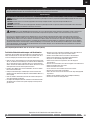
WARNING: Read the ENTIRE instruction manual to become familiar with the features of the product before operating. Failure to operate the product
correctly can result in damage to the product, personal property and cause serious injury.
This is a sophisticated hobby product. It must be operated with caution and common sense and requires some basic mechanical ability. Failure to oper-
ate this Product in a safe and responsible manner could result in injury or damage to the product or other property. This product is not intended for use by
children without direct adult supervision. Do not use with incompatible components or alter this product in any way outside of the instructions provided by
Horizon Hobby, Inc. This manual contains instructions for safety, operation and maintenance. It is essential to read and follow all the instructions and warn-
ings in the manual, prior to assembly, setup or use, in order to operate correctly and avoid damage or serious injury.
2

EN
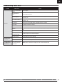
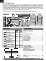
Table of Contents
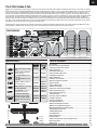
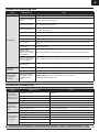
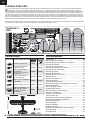
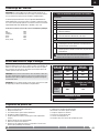
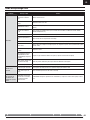
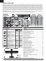
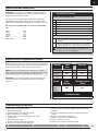
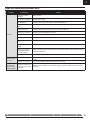
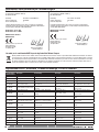
Specifi cations
8.15 lb
(3.7 kg)
55.8 in (1419mm)
84.6 in (2150mm)
BL50 Brushless Outrunner Motor,
525Kv
Included Included
60-Amp Pro Switch-Mode BEC
Brushless ESC (V2)
Installed Installed
(4) 26 g Digital MG Mini Servo
(EFLR7145)
(2) 13 g Digital MG Micro Servo
(EFLR7155)
Installed Installed
Spektrum
™
AR635, 6-Channel
AS3X
®
Sport Receiver
Installed
Required to
Complete
Battery: 3200mAh 22.2V 6S 30C
Li-Po (EFLB32006S30)
Required to
Complete
Required to
Complete
Battery Charger: 6-cell Li-Po
battery balancing charger
Required to
Complete
Required to
Complete
Recommended Transmitter:
Full-Range 6 channel 2.4GHz
with Spektrum DSM2
®
/DSMX
®
technology with programmable
Mixing.
Required to
Complete
Required to
Complete
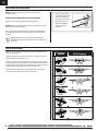
Box Contents
AS3X System .......................................................................................4
Receiver Selection and Installation .......................................................4
Transmitter and Receiver Binding .........................................................5
Battery Installation ...............................................................................6
Low Voltage Cutoff (LVC) ......................................................................6
Arming the ESC and Receiver...............................................................7
Landing Gear Installation .....................................................................8
Rudder Installation ...............................................................................9
Horizontal Tail Installation ..................................................................10
Motor and Propeller Installation .........................................................11
Wing Installation ................................................................................12
Center of Gravity (CG) .......................................................................14
Control Direction Test .........................................................................14
Control Horn and Servo Arm Settings .................................................14
Control Surface Centering ..................................................................15
AS3X Control Direction Test ..............................................................15
Transmitter Setup .............................................................................16
Dual Rates, Expos and Mixing ............................................................16
Prefl ight Preparation ..........................................................................16
Flying Tips and Repairs ......................................................................17
Post Flight Maintenance .....................................................................18
Optional Tow Release Installation .......................................................18
Optional Camera Mount Installation....................................................19
AMA National Model Aircraft Safety Code ...........................................20
Troubleshooting Guide AS3X .............................................................21
Troubleshooting Guide .......................................................................22
Limited Warranty ...............................................................................23
Contact Information ...........................................................................24
FCC Information .................................................................................24
Compliance Information for the European Union .................................24
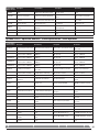
Replacement Parts .............................................................................90
Optional Parts ....................................................................................91
1100 in²
(71 dm²)
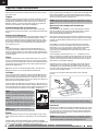
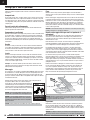
The E-flite Carbon-Z Cub
T
hank you for purchasing the E-fl ite
®
Carbon-Z
®
Cub aircraft. Like the full-scale Carbon Cub SS airplane available from Cub Crafters, in your hands is a remark-
ably versatile airplane designed by World Aerobatic Champion, Quique Somenzini, to deliver a pleasure cruiser with incredible muscle. In conjunction with rigid
Carbon-Z construction, the remarkable AS3X
®
system built into the included Spektrum
™
AR635 receiver (BNF Basic version only) makes it possible for you to
experience a performance envelope that’s wider than ever before possible, more stable and crisp on the controls. This means that no matter how you like to fl y,
you’ll enjoy both rock-solid stability and maneuverability without any sacrifi ce in precision or control feel. Although this aircraft may look tame, its brushless power
system has been specially chosen to offer brutish performance for unbelievable STOL performance as well as unexpected 3D aerobatic agility. In addition, its
ready to become your favorite tow plane for sailplanes and can easily carry a camera above the cabin making this already amazing model the ultimate utility air-
craft. Plus, you can make your Carbon-Z Cub even more versatile by adding the optional Carbon-Z Cub Float Set to the hard points already built into the airframe
that allow you to make virtually any place in the world a viable fl ying site.
Your Carbon-Z Cub aircraft represents the benchmark of performance and aerobatic versatility. And it’s brought to you at both the high-value Bind-N-Fly
®
Basic
and Plug-N-Play
®
completion levels. All you have to do next is read and apply the information presented in this instruction manual.
3

EN
®
AS3X System
Horizon Hobby has always made RC sport, scale and unique aircraft with
the kind of performance experts appreciate. First used in Blade
®
ultra micro
fl ybarless helicopters, MEMS sensor technology within the Artifi cial Stability--3
axis (AS3X) System has been specifi cally tuned for airplanes helping invisibly
correct for turbulence, torque and tip stalls.
Now the exclusive AS3X Stabilization system makes the leap from Ultra Micro
aircraft to high performance parkfl yers with the AR635 receiver. The preci-
sion and performance available from AS3X equipped Ultra Micro airplanes has
heralded a new era of performance, and with the AR635, that performance is
introduced for larger airplanes.
The outstanding control agility delivers an ultra smooth, locked-in feel that
obeys your every command with performance that’s natural feeling. It’s so
gratifying, in fact, that it’s as though you’re the RC pilot of an expertly tuned,
giant-scale aircraft. Welcome to AS3X, your parkfl yer will never be the same! To
see what we mean, go to www.E-fl iteRC.com/AS3X.
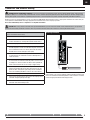
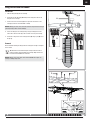
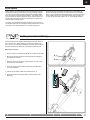
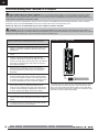
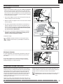
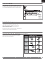
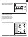
Receiver Selection and Installation
The Spektrum AR635 receiver is recommended for ths airplane. If you choose
to install another receiver, ensure that is at least a 6-channel full range (sport)
receiver. Refer to your receiver manual for correct installation and operation
instructions.
Installation (AR635 shown)
1. Remove the screw (A) and radio hatch (B) from the top of the fuselage.
2. Install your full range (sport) receiver in the fuselage using double-sided
servo tape.
3. Attach the elevator and rudder servo connectors to the appropriate chan-
nels of the receiver.
4. Attach the aileron Y-harness to the aileron channel of the receiver.
5. Attach the Flaps Y-harness to the AUX1.
6. Attach the ESC connector to the throttle channel of the receiver.
A
B
4

EN
Binding is the process of programming the receiver to recognize the GUID (Globally Unique Identifi er) code of a single specifi c transmitter. You need to ‘bind’ your
chosen Spektrum
™
DSM2
®
/DSMX
®
technology equipped aircraft transmitter to the receiver for proper operation.
Please visit www.bindnfl y.com for a complete list of compatible transmitters.
CAUTION: When using a Futaba
®
transmitter with a Spektrum DSM module, you must reverse the throttle channel and rebind. Refer to your Spektrum
module manual for binding and failsafe instructions. Refer to your Futaba transmitter manual for instructions on reversing the throttle channel.
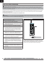
Read the transmitter instructions for binding to a receiver
(location of transmitter’s Bind control).
1. Make sure the transmitter is powered off.
2. Move the transmitter controls to neutral (fl ight controls: rudder,
elevators and ailerons) or to low positions (throttle, throttle trim).**
3. Install a bind plug in the receiver bind port.
4. Connect the fl ight battery to the ESC, then power on the ESC switch.
The ESC will produce a series of sounds. One long tone, then 6 short
tones confi rm that the LVC is set correctly for the ESC. The orange
bind LED on the receiver will begin to fl ash rapidly.
5. Power on the transmitter while holding the transmitter bind button
or switch. Refer to your transmitter’s manual for binding button or
switch instructions.
6. When the receiver binds to the transmitter, the orange bind light on
the receiver will turn solid and the ESC will produce a series of three
ascending tones. The tones indicate the ESC is armed, provided the
throttle stick and throttle trim are low enough to trigger arming.
7. After binding, the 3 LEDs (blue, yellow and red) on the receiver
will fl ash. The fl ashing indicates the gain setting for each axis. The
quicker the fl ash, the higher the gain setting. For more information,
refer to the “Initializing the AR635” section in the receiver manual.
8. Remove the bind plug from the bind port.
9. Safely store the bind plug (some owners attach the bind plug to their
transmitter using two-part loops and clips).
10. The receiver should retain the binding instructions received from the
transmitter until another binding is done.
** The throttle will not arm if the transmitter’s throttle control is not put at the
lowest position. If you encounter problems, follow the binding instructions and
refer to the transmitter Troubleshooting Guide for other instructions. If needed,
contact the appropriate Horizon Product Support offi ce.
Transmitter and Receiver Binding
Bind Plug Installation
WARNING AGAINST COUNTERFEIT PRODUCTS: If you ever need to replace your Spektrum receiver found in a Horizon Hobby product, always purchase
from Horizon Hobby, Inc. or a Horizon Hobby authorized dealer to ensure authentic high-quality Spektrum product. Horizon Hobby, Inc. disclaims all support and
warranty with regards, but not limited to, compatibility and performance of counterfeit products or products claiming compatibility with DSM or Spektrum.
5

EN
®
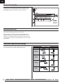
Low Voltage Cutoff (LVC)
Battery Installation
Battery Selection
• We recommend the E-fl ite 3200mAh 22.2V 6S Li-Po battery
(EFLB32006S30). Refer to the Optional Parts List for other E-fl ite batteries.
If using a battery other than those listed, the battery should be within the
range of capacity, dimensions and weight of the E-fl ite Li-Po battery packs
to fi t in the fuselage without changing the center of gravity a large amount.
1. Press the latch button (A) to lift the rear edge of the canopy hatch, then pull
the hatch up and back from the fuselage.
2. Apply the included strip of hook and loop tape to the bottom of your
battery(s).
3. For the recommended CG, install the battery(s) in the middle of the com-
partment, then press the battery(s) onto the hook and loop strip. Close the 2
hook and loop straps around the battery(s). See the Adjusting the Center
of Gravity instructions for more information.
4. Connect a fully charged battery(s) to the ESC. See the Arming the ESC
instructions for correct connection of the battery to the ESC.
5. Reinstall the canopy hatch.
Tip: The ESC switch in the front left corner of the battery compart-
ment must be powered on for Arming the ESC.
Dual Battery Setup
An optional Y-harness (EFLAEC308 sold separately), is available to connect
(2) 3S Li-Po batteries in series to the ESC instead of (1) 6S Li-Po battery.
If (2) 3S Li-Po batteries are used, join them in a stack using hook and loop
strips. Secure the battery stack in place using the instructions described in
steps 2 and 3 above.
A
When a Li-Po battery is discharged below 3V per cell, it will not hold a charge.
The ESC protects the fl ight battery from over-discharge using Low Voltage Cut-
off (LVC). Before the battery charge decreases too much, LVC removes power
supplied to the motor. Power to the motor pulses, showing that some battery
power is reserved for fl ight control and safe landing. When the motor pulses,
land the aircraft immediately and recharge the fl ight battery.
Disconnect and remove the Li-Po battery from the aircraft after use to prevent
trickle discharge. Charge your Li-Po battery to about half capacity before stor-
age. During storage, make sure the battery charge does not fall below 3V per
cell.
TIP: Monitor your aircraft battery’s voltage before and after fl ying by
using a Li-Po Cell Voltage Checker (EFLA111, sold separately).
6

EN
Arming the ESC and Receiver
Arming the ESC also occurs after binding as previously described, but subse-
quent connection of a fl ight battery requires the steps below.
AS3X
The AS3X system will not activate until the throttle stick or trim is increased for
the fi rst time. Once the AS3X is active, the control surfaces may move rapidly
on the aircraft. This is normal. AS3X will remain active until the battery is
disconnected.
NOTICE: Due to increased servo power demands, only use the 60-Amp Pro
Switch-Mode BEC Brushless ESC (EFLA1060B V2) with the AR635 receiver. Use
of any other ESC presently available may result in damage to the aircraft.
DO NOT connect the battery while the throttle stick is at full or the ESC will go
into programming mode. If a musical tone sounds after 5 seconds, immediately
disconnect the battery, then lower the throttle. Refer to the ESC manual (avail-
able separately) for more information.
CAUTION: Always keep hands away from the propeller. When armed,
the motor will turn the propeller in response to any throttle movement.
CAUTION: Always disconnect the Li-Po battery from the aircraft receiver
when not fl ying to avoid over-discharging the battery. Batteries discharged to a
voltage lower than the lowest approved voltage may become damaged,
resulting in loss of performance and potential fi re when batteries are charged.
1. Lower the throttle and throttle trim to lowest settings. Power on the
Transmitter, then wait 5 seconds.
2. Remove the battery hatch and install the flight battery to the hook and
loop strip, then connect the battery to the ESC, noting proper polarity.
3. Power ON the ESC switch (A) on the left side of the battery compartment.
Keep the aircraft immobile on its wheels away from wind for 5 seconds.
• The ESC will sound a series of tones (refer to step 4 of the
binding instructions for more information).
• An LED will light on the receiver (the red, blue and green gain
LEDs will also fl ash).
If the ESC sounds a continuous double beep after the flight battery is
connected, recharge or replace the battery.
For further explanation of the gain lights, refer to the “Initializing the AR635”
section of the AR635 receiver manual.
TIP: The ESC switch enables you to easily disarm the propeller while
you are not fl ying, but will still draw current from the battery.
A
77

EN
®
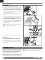
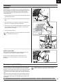
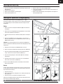
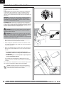
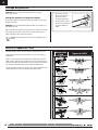
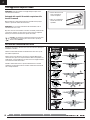
Assembly
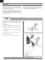
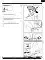
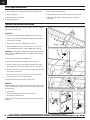
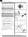
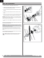
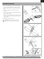
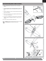
1. Install 2 tundra tires (A) on the main strut (B) using 4 wheel collars (C) as
shown. Ensure the set screws (D) are aligned with the fl at spots on the
strut. Apply threadlock and tighten.
2. Compress the legs of the strut assembly and insert the top of the assembly
into the slot (E) in the bottom of the fuselage. The strut is fully installed
when the L-bend (F) is completely recessed in the fuselage.
3. Push the legs of the fairing strut (G) together and install it in the rear slot
(H) in the fuselage as was done with the main gear strut.
4. Install the left and right strut brackets (I) (marked L and R) in the respective
slots on the bottom of the fuselage using 4 screws (J).
5. Install the left (K) and right (L) fairings on the respective sides of the fairing
strut, then install the fairings on the main gear strut.
Where needed, disassemble in reverse order.
Landing Gear Installation
A
C
B
E
F
H
G
D
I
J
L
K
Required Adhesives:
Thread Lock
D
8

EN
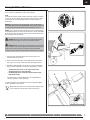
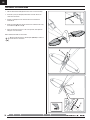
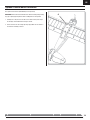
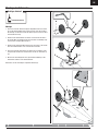
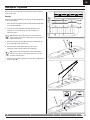
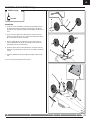
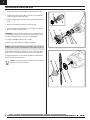
Rudder Installation
Assembly
1. Slide the rudder’s CA hinges (A) in the hinge slots (B) of the vertical tail.
2. Install the screw (C) in the rudder mount.
3. Rest the aircraft on its nose, holding the tail up so the thin CA
(cyanoacrylate adhesive) will flow into the slots.
4. Bend the hinges by turning the rudder left, then carefully apply thin CA to
each hinge in the right side of each slot.
5. When the CA is dry, turn the rudder to the right and apply CA in the left
side of each slot.
6. Connect the ball link (D) to the rudder control horn’s outermost
hole (E) using a screw (F) and nut (G). Ensure the rudder servo arm
is in the correct position, then adjust the ball link on the linkage to
center the rudder.
A
A
B
C
C
Required Adhesives:
Thin CA
D
E
F
G
F
9

EN
®
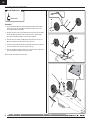
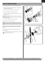
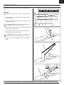
Horizontal Tail Installation
1. Slide the horizontal tail tube (A) into the hole in the rear of the fuselage.
2. Install the 2 piece (left and right) horizontal tail as shown. Ensure the
control horn faces down.
3. Install 4 screws (B) in the front and rear holes in the bottom of the
horizontal tail.
4. Attach the ball link (C) to the elevator control horn’s outermost hole using
the included nut (D) and screw (E).
5. Ensure the elevator servo arm is in the correct position, then adjust the
linkage to center the elevator.
When needed, disassemble in reverse order.
Tip: Use needle-nose pliers or ball link pliers (RV01005) to remove or
install a link on a control horn.
A
B
D
E
E
C
C
10

EN
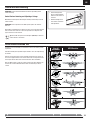
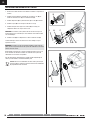
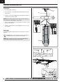
Motor and Propeller Installation
1. Correctly align and connect the motor wire colors with the ESC wires.
2. Install the motor (A) with pre-installed X-mount (B) on the fuselage using 4
screws (C) and 4 lockwashers (D).
3. Install the collet (E), and back plate (F) on the motor shaft (G).
4. Install the cowling (H) on the fuselage using 2 screws (I).
5. Install the spinner back plate (J), propeller (K) and nut (L) on the collet. Use
a tool to tighten the nut.
IMPORTANT: The propeller size numbers (15 x 5.5) must face out from the
motor for correct propeller operation. Ensure the nut holds the propeller tightly
without damaging the propeller.
6. Install the spinner (M) on the collet using the screw (N).
Disassemble in reverse order. Not all wiring shown.
NOTICE: If the propeller is not balanced, the aircraft may vibrate, causing the
stabilization system to not operate correctly and/or decrease the life of the
servos.
Horizon Hobby does not warrant replacement if the servos are used under
extreme vibration or the stabilization system is used with an unbalanced
propeller.
For more information, view John Redman’s propeller balancing video at
www.horizonhobby.com.
Tip: We recommend removal of the propeller before any radio system
setup or transport of your aircraft.
FH
E
E
H
F
G
H
I
M
N
L
JK
K
J
B
A
A
CD
C
D
C
11

EN
®
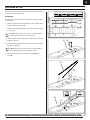
Wing Installation
Before each fl ight, ensure all wing connectors and fasteners are secure.
Assembly
Assemble both wings using the following steps. (Only the right wing shown)
1. Install 6 vortex generators (A) in the wing channels (B) by using double-
sided tape (C).
2. Install the vertical bracket (D) on the wing mounts using 2 screws (E) and
2 lock nuts (F).
TIP: DO NOT overtighten lock nuts on the screws. Ensure the vertical
brackets can pivot freely on the wing mounts.
3. Install the wide front strut (G) on the front strut mounts using a screw (H)
and lock nut (I).
4. Install the narrow rear strut (J) on the rear strut mount using a screw (K)
and lock nut (L).
TIP: DO NOT overtighten lock nuts on the screws. Ensure the struts
can pivot freely in the strut mounts.
5 Attach the vertical bracket to the struts using 2 pins (M) and 2 R-clips (N).
ED
F
F
G
J
J
H
I L
K
NM
A
C
B
A
A
A
C
B
12

EN
Installation
1. Slide the wing tube (A) into the fuselage.
2. Install the left and right wing (B and C) over the wing tube and into the
wing slot of the fuselage.
3. Connect the servo connectors (D) to the respective connectors on the
fuselage (connectors are marked AIL or FLAP).
NOTICE: Always put excess servo connector wire into the pocket of the wing to
prevent pinching of wires or other damage.
4. Secure the wings on the fuselage using 2 long screws (E) in the front
holes and 2 shorter screws (F) in the rear holes in the top of the wings.
5. Install the 2 wing struts on the fuselage mount (G) using 2 pins (H) and 2
R-clips (I).
Removal
We recommend removing the wings from the fuselage for storage or transport
of the aircraft.
TIP: Remove the vertical bracket pins and clips from the struts to
pivot the brackets and struts down to the wings. Wing struts do not
need to be disassembled to be removed.
NOTICE: Always secure loose parts after removal. DO NOT FLY if parts are
missing or damage may result.
Wing Installation continued
AILE
FLAP
AILE
FLAP
D
A
B
C
B
F
E
E
G
H
I
H
13

EN
®
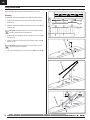
Center of Gravity (CG)
The CG location is measured from the leading edge of the wing at the root.
This CG location has been determined with the recommended Li-Po battery
(EFLB32006s30) installed in the middle of the battery compartment.
120mm
back from
leading edge
at the root.
Control Direction Test
Move the controls on the transmitter to make sure the aircraft control surfaces
move correctly and in the proper direction or reverse a servo.
After performing the Control Test, correctly set the failsafe. Make sure the
transmitter controls are at neutral and the throttle and throttle trim are in the
low position, then rebind the airplanes to your transmitter. If the receiver loses
its connection to the transmitter, the failsafe will drive the servos to the settings
made at binding.
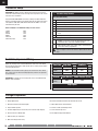
Control Horn and Servo Arm Settings
The tabe to the right shows the factory settings for the control horns and servo
arms. Fly the aircraft at factory settigns before making changes.
Factory Settings
Horns Arms
Elevator
Rudder
Ailerons
Flaps
14

EN
Control Surface Centering
AS3X Control Direction Test
IMPORTANT: Perform the Control Direction Test before performing control
surface centering.
Control Surface Centering and Adjusting a Linkage
While AS3X is inactive (before advancing the throttle), mechanically center the
control surfaces.
IMPORTANT: Correct operation of the AS3X system requires sub-trim and
trim at 0.
After binding a transmitter to the airplanes receiver, set the trims and sub-trims
to 0, ensure the servo arms are in the correct positions, then adjust the link-
ages to center the control surfaces.
Tip: Use needle-nose pliers or ball link pliers (RV01005) to remove or
install a link on a control horn.
• Turn the linkage clock-
wise or counterclockwise
until the control surface is
centered.
• Attach the linkage to the
servo arm or control horn
after adjustment.
Assemble the aircraft and bind your transmitter to the receiver before perform-
ing this Test.
Activate the AS3X system by advancing the throttle to 25%, then fully lowering
the throttle.
Move the aircraft as shown to ensure the AS3X system moves the control sur-
faces in their proper direction. If the control surfaces do not respond as shown,
do not fl y the aircraft. Refer to the receiver manual for more information.
Once the AS3X system is active, the control surfaces may move rapidly on the
aircraft. This is normal. AS3X will remain active until the battery is discon-
nected.
Aircraft
movement
AS3X Reaction
ElevatorAileronRudder
15

EN
®
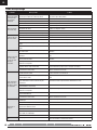
Transmitter Setup
9
Transmitter Setup Checklist
Before binding for Computerized Transmitters (DX6i, DX7/DX7se,
DX7s, DX8, DX10t, DX18):
1. Choose a blank model memory.
2. Choose Wing/Aircraft Type for single aileron servo.
3. Enable the Flap funtion in your Transmitter
4. Set all trim and sub-trims to NEUTRAL (0%).
5 Set servo travel values to Quique’s recommended settings.
6. Set the Dual Rate value according to the Dual Rate and Expo
chart.
7. Set fl ap-elevator mixing
After binding:
1. DO NOT use sub-trims to make fi ne adjustments. Off-center
subtrim will affect servo travel and AS3X operation.
2. Adjust linkage lengths so the control surfaces center when the
servo arm is close to perpendicular
CAUTION: For safe operation, always re-bind the airplane after
setup is complete to ensure the failsafe is updated with the latest
setup.
IMPORTANT: The AR635 receiver’s default setting in this aircraft is normal
mode. We recommend that you do not change this setup. Refer to the receiver
manual for more information.
A programmable DSM2/DSMX six-channel (or better) transmitter with Dual
Rates is required for fl ying this aircraft with fl aps and the optional tow release.
The Spektrum
™
DX6i, DX7s, DX8, DX10t, DX18 and JR
®
X9503, 11X or 12X
transmitters may be used.
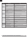
Below are Quique’s recommended settings for Servo Travel.
Throttle 100%
Aileron 125%
Elevator 125%
Rudder 125%
Channel 5 100%
Channel 6 (Flaps) 125%
Dual Rates, Expos and Mixing
Adjust rate and expo to the recommended values shown in the chart below.
We recommend mixing fl aps to down elevator 42% to reduce pitch up tenden-
cies during fl ap operation.
NOTICE: To ensure AS3X functions properly, do not lower rate values below
50%. If lower rates are desired, manually adjust the position of the pushrods
on the servo arm.
IMPORTANT: If oscillation occurs at high speed, refer to the Troubleshooting
Guide for more information.
Dual Rate High Rate
Expo
Low Rate
Expo
Aileron 100%
0%
70%
0%
Elevator 100%
0%
70%
0%
Rudder 100%
0%
70%
0%
Prefl ight Preparation
1. Remove and inspect contents.
2. Charge fl ight battery.
3. Read this instruction manual thoroughly.
4. Fully assemble airplanes.
5. Install the fl ight battery in the aircraft (once it has been fully charged).
6. Check the Center of Gravity (CG)
7. Bind aircraft to your transmitter.
8. Make sure linkages move freely.
9. Perform the Control Direction Test with the transmitter.
10. Perform the AS3X Control Direction Test with the aircraft.
11. Adjust fl ight controls and transmitter.
12. Perform a radio system Range Check.
13. Find a safe and open area.
14. Plan fl ight for fl ying fi eld conditions.
Channel Flaps (Master) Down Elevator (Slave)
Mix Value
(Linear)
100% 42%
Flaps Speed
2 seconds
16

EN
Flying Tips and Repairs
Always
decrease throttle at
propeller strike.
Consult local laws and ordinances before choosing a fl ying location.
Flying Field
Always choose a wide-open space for fl ying your aircraft. It is ideal for you
to fl y at a sanctioned fl ying fi eld. If you are not fl ying at an approved site,
alwaysavoid fl ying near houses, trees, wires and buildings. You should also
be careful to avoid fl ying in areas where there are many people, such as busy
parks, schoolyards, or soccer fi elds.
Range Check your Radio System
Before you fl y, range check the radio system. Refer to your specifi c transmitter
instruction manual for range test information.
Understanding Oscillation
Once the AS3X system is active (after advancing the throttle for the fi rst time),
you will normally see the control surfaces react to aircraft movement. In
some fl ight conditions, you will see oscillation. If oscillation occurs, decrease
airspeed. If oscillation persists, refer to the Troubleshooting Guide for more
information.
Takeoff
Place the aircraft in position for takeoff (facing into the wind). Set your trans-
mitter in low rate and gradually increase the throttle to ¾ to full and steer with
the rudder. Pull back gently on the elevator and climb to a comfortable altitude.
Flying
Fly the airplane and trim it for level fl ight at ¾ throttle. After landing, adjust
the linkages mechanically to account for trim changes, then reset the trims to
neutral. Ensure the aircraft will fl y straight and level with no trim or sub-trim.
Tip: If using more than 8 clicks of fl ight trim, mechanically adjust the linkage
so less trim is needed, or AS3X operation may be affected.
Landing
For your fi rst fl ights and with the recommended battery pack (EFLB32006s30),
set your transmitter timer or a stopwatch to 7 minutes. Adjust your timer
for longer or shorter fl ights once you have fl own the model. When the motor
pulses, land the aircraft immediately and recharge the fl ight battery. It is not
recommended to fl y the battery to LVC.
Make sure to land into the wind. Fly the aircraft to approximately 36 inches
(90 cm) or less above the runway, using a small amount of throttle for the
entire descent. Keep the throttle on until the aircraft is ready to fl are. During
fl are, keep the wings level and the aircraft pointed into the wind. Gently lower
the throttle while pulling back on the elevator to bring the aircraft down on its
wheels.
NOTICE: If a crash is imminent, reduce the throttle and
trim fully. Failure to do so could result in extra damage
to the airframe, as well as damage to the ESC and
motor.
NOTICE: After any impact, always ensure the receiver
is secure in the fuselage. If you replace the receiver,
install the new receiver in the same orientation as the
original receiver or damage may result.
NOTICE: Crash damage is not covered under warranty.
Flaps
When using fl aps, takeoffs and landings are shorter. When taking off, the tail
will come off the ground quicker for better rudder control during the takeoff
roll.
During landing, the fl aps allow a landing approach to be steeper with the ability
to use more throttle. Flaps make the plane come in at a slower airspeed
and make it easier to fl are and settle in for a smooth landing.
When deploying the fl aps, slow the aircraft down to 1/4 throttle. If the fl aps
are deployed when the aircraft is at a higher speed, the aircraft will pitch up.
Set your down elevator to fl ap mixing at 42% to reduce the pitch up tendency.
NOTICE: When using fl aps with this airplane, down elevator to fl ap mixing is
required. Failure to do so may result in loss of control or a crash.
Water Takeoff and Landing Using the Optional Float Set
Only use the fl oats if you are comfortable fl ying your aircraft and have
repeatedly taken off, fl own and landed with success. Flying off water poses a
higher risk to the airplane because the electronics can fail if fully immersed in
water.
Always ensure the optional fl oats (EFL1045017, sold separately) are secure on
the fuselage and that the fl oat rudder linkage is correctly connected and moves
freely before putting the aircraft in water.
To take off on water, steer with the rudder and slowly increase the throttle.
Keep the wings level on takeoff. Hold a small amount (1/4–1/3) of up
elevator and the aircraft will lift off once fl ying speed is reached. Avoid rapidly
increasing the throttle as torque from the motor may cause the aircraft to roll
to the left when on water.
To land this aircraft on water, fl y the aircraft to a couple of feet off the surface
of the water. Reduce throttle and add up elevator to fl are the aircraft.
When taxiing, you must use throttle to move the aircraft forward, but steer with
the rudder stick. The stick will turn both the aircraft rudder and a small rudder
attached to the left fl oat.
Avoid taxiing cross wind if there is a breeze, as this can cause the aircraft to
fl ip over if wind gets under the upwind wing. Taxi 45 degrees into the direction
of the wind (not perpendicular to the wind) and use aileron to hold the upwind
wing down. The aircraft will naturally try to face into the wind when taxiing.
Always fully dry the aircraft after landing on water.
Wind
NOTICE: When you are fi nished fl ying, never leave the airplane in direct sun-
light or a hot, enclosed area such as a car. Doing so can damage the foam.
Repairs
Thanks to the Z-Foam
™
material in this aircraft, repairs to the foam can be
made using virtually any adhesive (hot glue, regular CA, epoxy, etc). When parts
are not repairable, see the Replacement Parts List for ordering by item number.
For a listing of all replacement and optional parts, refer to the list at the end of
this manual.
NOTICE: Use of CA accelerant on your aircraft can damage paint. DO NOT
handle the aircraft until accelerant fully dries.
17

EN
®
1. Disconnect fl ight battery from ESC (Required for Safety and battery life).
2. Power off transmitter.
3. Remove fl ight battery from aircraft.
4. Recharge fl ight battery.
5. Repair or replace all damaged parts.
6. Store fl ight battery apart from aircraft and monitor the battery charge.
7. Make note of fl ight conditions and fl ight plan results, planning for
future fl ights.
Post Flight Maintenance
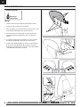
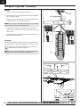
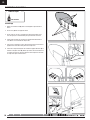
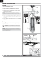
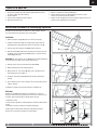
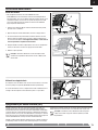
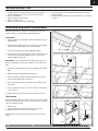
Optional Tow Release Installation
This aircraft is designed to tow 2- to 3-meter sailplanes. Refer to your sailplane
manual for tow line instructions.
Installation
1. Remove the screw (A) and radio hatch (B) from the top of the fuselage.
2. Install a 13 g tow release servo (C) (EFLR7155, sold separately) inside the
fuselage using 2 screws (D).
3. Insert the servo connector in the GEAR port of the receiver.
4. Operate the GEAR channel on your transmitter so you see the servo arm
move up (GEAR Switch position 1) and down (GEAR switch position 0).
IMPORTANT: In your transmitter, the GEAR channel (Channel 5) servo direction
servo must be set to NORMAL with servo travel at 100% for correct operation
of the tow release.
5. Move the servo arm down using the GEAR switch.
6. Remove the screw (E) and servo arm (F) from the servo. (fi gure 1)
7. Install the Z-bend of the tow release pin (G) (included with the aircraft) in
the innermost hole of the arm from the bottom of the servo arm. (fi gure 2)
8. Install the tow release pin in the tow release housing (H) that is molded into
the top portion of the fuselage.
9. Attach the servo arm to the servo using the screw so the center of the
servo arm points to the 7 o’clock position. (fi gure 3)
10. Install the radio hatch on the fuselage reusing the screw.
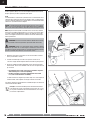
Operation
Operate the GEAR channel on your transmitter to ensure the pin retracts below
the slot in the housing. If the pin does not retract appropriately, adjust the servo
arm mechanically.
1. Retract the pin.
2. Insert a tow line loop into the housing slot and over the pin.
3. Extend the pin to hold the tow line.
Always put the tension on a tow line and cycle the release before aero-towing
a sailplane.
A
B
D
E
F
E
(fi g.2)
(fi g.3)
H
(fi g.1)
G
18

EN
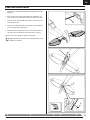
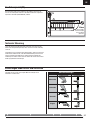
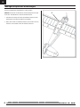
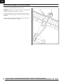
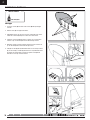
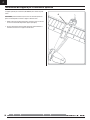
Optional Camera Mount Installation
The optional camera mount (EFL1045023) is sold separately.
IMPORTANT: Consult local laws and ordinances before installing and operating
any type of photograph-capable or video recording device in this product.
1. Carefully cut a slot (the size of the tab on the camera mount) in the top of
the fuselage centered between the wings as shown.
2. Secure the mount on the fuselage by using epoxy. Make sure the mount is
secure before installing a camera.
A
19

EN
®
AMA National Model Aircraft Safety Code
Effective January 1, 2011
A. GENERAL
A model aircraft is a non-human-carrying aircraft capable of sustained fl ight
in the atmosphere. It may not exceed limitations of this code and is intended
exclusively for sport, recreation and/or competition. All model fl ights must
be conducted in accordance with this safety code and any additional rules
specifi c to the fl ying site.
1. Model aircraft will not be fl own:
(a) In a careless or reckless manner.
(b) At a location where model aircraft activities are prohibited.
2. Model aircraft pilots will:
(a) Yield the right of way to all man carrying aircraft.
(b) See and avoid all aircraft and a spotter must be used when appropriate.
(AMA Document #540-D-See and Avoid Guidance.)
(c) Not fl y higher than approximately 400 feet above ground level within
three (3) miles of an airport, without notifying the airport operator.
(d) Not interfere with operations and traffi c patterns at any airport, heliport
or seaplane base except where there is a mixed use agreement.
(e) Not exceed a takeoff weight, including fuel, of 55 pounds unless in
compliance with the AMA Large Model Aircraft program. (AMA
Document 520-A)
(f) Ensure the aircraft is identifi ed with the name and address or AMA
number of the owner on the inside or affi xed to the outside of the model
aircraft. (This does not apply to model aircraft fl own indoors).
(g) Not operate aircraft with metal-blade propellers or with gaseous boosts
except for helicopters operated under the provisions of AMA Document
#555.
(h) Not operate model aircraft while under the infl uence of alcohol or while
using any drug which could adversely affect the pilot’s ability to safely
control the model.
(i) Not operate model aircraft carrying pyrotechnic devices which explode
or burn, or any device which propels a projectile or drops any object
that creates a hazard to persons or property.
Exceptions:
• Free Flight fuses or devices that burn producing smoke and are
securely attached to the model aircraft during fl ight.
• Rocket motors (using solid propellant) up to a G-series size may
be used provided they remain attached to the model during fl ight.
Model rockets may be fl own in accordance with the National
Model Rocketry Safety Code but may not be launched from
model aircraft.
• Offi cially designated AMA Air Show Teams (AST) are authorized to
use devices and practices as defi ned within the Team AMA
Program Document (AMA Document #718).
(j) Not operate a turbine-powered aircraft, unless in compliance with the
AMA turbine regulations. (AMA Document #510-A).
3. Model aircraft will not be fl own in AMA sanctioned events, air shows or
model demonstrations unless:
(a) The aircraft, control system and pilot skills have successfully
demonstrated all maneuvers intended or anticipated prior to the
specifi c event.
(b) An inexperienced pilot is assisted by an experienced pilot.
4. When and where required by rule, helmets must be properly worn and
fastened. They must be OSHA, DOT, ANSI, SNELL or NOCSAE approved or
comply with comparable standards.
B. RADIO CONTROL
1. All pilots shall avoid fl ying directly over unprotected people, vessels,
vehicles or structures and shall avoid endangerment of life and property
of others.
2. A successful radio equipment ground-range check in accordance with
manufacturer’s recommendations will be completed before the fi rst fl ight
of a new or repaired model aircraft.
3. At all fl ying sites a safety line(s) must be established in front of which all
fl ying takes place (AMA Document #706-Recommended Field Layout):
(a) Only personnel associated with fl ying the model aircraft are allowed at
or in front of the safety line.
(b) At air shows or demonstrations, a straight safety line must be
established.
(c) An area away from the safety line must be maintained for spectators.
(d) Intentional fl ying behind the safety line is prohibited.
4. RC model aircraft must use the radio-control frequencies currently allowed
by the Federal Communications Commission (FCC). Only individuals
properly licensed by the FCC are authorized to operate equipment on
Amateur Band frequencies.
5. RC model aircraft will not operate within three (3) miles of any pre-existing
fl ying site without a frequency-management agreement (AMA Documents
#922-Testing for RF Interference; #923- Frequency Management
Agreement)
6. With the exception of events fl own under offi cial AMA Competition
Regulations, excluding takeoff and landing, no powered model may be
fl own outdoors closer than 25 feet to any individual, except for the pilot
and the pilot’s helper(s) located at the fl ight line.
7. Under no circumstances may a pilot or other person touch a model aircraft
in fl ight while it is still under power, except to divert it from striking an
individual. This does not apply to model aircraft fl own indoors.
8. RC night fl ying requires a lighting system providing the pilot with a clear
view of the model’s attitude and orientation at all times.
9. The pilot of a RC model aircraft shall:
(a) Maintain control during the entire fl ight, maintaining visual contact
without enhancement other than by corrective lenses prescribed for
the pilot.
(b) Fly using the assistance of a camera or First-Person View (FPV) only
in accordance with the procedures outlined in AMA Document #550.
FAA Information
Prior to fl ying, contact your local or regional modeling organizations for
guidance and familiarize yourself with the current local rules and FAA
regulations governing model aviation in your location.
More information about model aviation can be found at www.modelaircraft.org.
The Federal Aviation Administration can be found online at www.faa.gov.
20
Seite laden ...
Seite laden ...
Seite laden ...
Seite laden ...
Seite laden ...
Seite laden ...
Seite laden ...
Seite laden ...
Seite laden ...
Seite laden ...
Seite laden ...
Seite laden ...
Seite laden ...
Seite laden ...
Seite laden ...
Seite laden ...
Seite laden ...
Seite laden ...
Seite laden ...
Seite laden ...
Seite laden ...
Seite laden ...
Seite laden ...
Seite laden ...
Seite laden ...
Seite laden ...
Seite laden ...
Seite laden ...
Seite laden ...
Seite laden ...
Seite laden ...
Seite laden ...
Seite laden ...
Seite laden ...
Seite laden ...
Seite laden ...
Seite laden ...
Seite laden ...
Seite laden ...
Seite laden ...
Seite laden ...
Seite laden ...
Seite laden ...
Seite laden ...
Seite laden ...
Seite laden ...
Seite laden ...
Seite laden ...
Seite laden ...
Seite laden ...
Seite laden ...
Seite laden ...
Seite laden ...
Seite laden ...
Seite laden ...
Seite laden ...
Seite laden ...
Seite laden ...
Seite laden ...
Seite laden ...
Seite laden ...
Seite laden ...
Seite laden ...
Seite laden ...
Seite laden ...
Seite laden ...
Seite laden ...
Seite laden ...
Seite laden ...
Seite laden ...
Seite laden ...
Seite laden ...
-
 1
1
-
 2
2
-
 3
3
-
 4
4
-
 5
5
-
 6
6
-
 7
7
-
 8
8
-
 9
9
-
 10
10
-
 11
11
-
 12
12
-
 13
13
-
 14
14
-
 15
15
-
 16
16
-
 17
17
-
 18
18
-
 19
19
-
 20
20
-
 21
21
-
 22
22
-
 23
23
-
 24
24
-
 25
25
-
 26
26
-
 27
27
-
 28
28
-
 29
29
-
 30
30
-
 31
31
-
 32
32
-
 33
33
-
 34
34
-
 35
35
-
 36
36
-
 37
37
-
 38
38
-
 39
39
-
 40
40
-
 41
41
-
 42
42
-
 43
43
-
 44
44
-
 45
45
-
 46
46
-
 47
47
-
 48
48
-
 49
49
-
 50
50
-
 51
51
-
 52
52
-
 53
53
-
 54
54
-
 55
55
-
 56
56
-
 57
57
-
 58
58
-
 59
59
-
 60
60
-
 61
61
-
 62
62
-
 63
63
-
 64
64
-
 65
65
-
 66
66
-
 67
67
-
 68
68
-
 69
69
-
 70
70
-
 71
71
-
 72
72
-
 73
73
-
 74
74
-
 75
75
-
 76
76
-
 77
77
-
 78
78
-
 79
79
-
 80
80
-
 81
81
-
 82
82
-
 83
83
-
 84
84
-
 85
85
-
 86
86
-
 87
87
-
 88
88
-
 89
89
-
 90
90
-
 91
91
-
 92
92


E-flite Carbon-Z Cub Benutzerhandbuch
- Kategorie
- Ferngesteuertes Spielzeug
- Typ
- Benutzerhandbuch
in anderen Sprachen
- English: E-flite Carbon-Z Cub User manual
- français: E-flite Carbon-Z Cub Manuel utilisateur
- italiano: E-flite Carbon-Z Cub Manuale utente
Verwandte Papiere
-
E-flite A6M5 Zero 300 Benutzerhandbuch
-
-
-
-
-
-
E-flite EFL011500 Bedienungsanleitung
-
-
E-flite EFL1045016 Benutzerhandbuch
-
E-flite Mystique EFL4905 Benutzerhandbuch
Sonstige Unterlagen
-
Horizon Hobby UMX YAK 54 3D Benutzerhandbuch
-
BNF P-51D Mustang 280 Benutzerhandbuch
-
HobbyZone HBZ5700 Bedienungsanleitung
-
-
ParkZone PKZ5275 Bedienungsanleitung
-
Spektrum USB-Interface UM AS3X Programmer Bedienungsanleitung
-
-
-
-