
Set Up Guide and Product Manual
roksan.com

INTRODUCTION
The Sara has been developed to elevate performance to a new level. When installed on
a high-quality turntable, the Sara allows the best performance of any chosen cartridge
to be realized.
The best possible components, materials and manufacturing processes were selected.
A uni-pivot design using a jewel seat and tungsten carbide pin is employed in the Sara
for the least friction and the maximum freedom of movement. Azimuth adjustment is
separate to the main counterweight. Internal wiring is high quality silver plated OFC
and our high quality HDC external cable is standard. These design features deliver an
uncoloured, dynamic, transparent and musical performance.
Not only does the Sara offer superb sound quality and trouble-free operation. The Sara
is a perfect match for Roksan’s turntables and cartridges and is compatible with those
from other manufacturers too. All adjustments have been designed to be easy and to
stay set in place for consistent performance and peace of mind
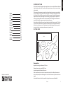
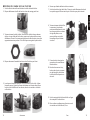
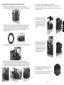
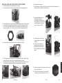
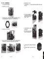
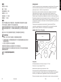
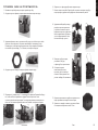
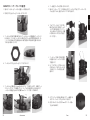
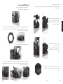
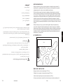
IN THE BOX
Cables
Counter-
Weight
Accessories
Arm
Arm Collar
& Lock Nut
Arm Carrier
Prerequisites
Required mounting hole diameter 23-25mm
Distance from pivot to spindle 222.5mm
Arm board material thickness 25mm max
If the turntable needs to moved or transported once the Sara is tted please remove
the arm tube (wand) to avoid damage as it is not ‘xed’ but rests in place under its own
weight
A record believed to be as at as possible to align the tonearm and headshell.
Roksan is a member of
1Sara
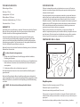
ENGLISH
English 1
Francais 11
Italia 21
Deutsch 31
Español 41
Português 51
Nederlands 61
中文 71
Русский 81
日本語 91
101
POLSKI 111

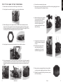
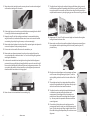
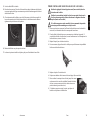
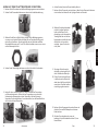
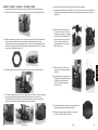
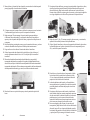
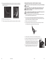
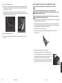
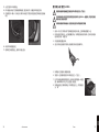
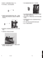
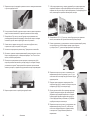
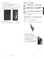
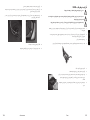
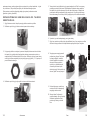
TO FIT THE SARA TO THE TURNTABLE:
1. Remove the arm collar and arm collar xing nut from the box
2. Gently drop the arm collar through the mounting hole from above
3. Whilst holding the collar in place, t the arm collar nut from beneath so that the
ridge on the nut ts against the arm board and gently tightening until nger tight.
It is recommended that the two grub screw holes on the side are at roughly 11 and
2 O’clock position when looking from the front of the turntable.
4. Gently drop the arm carrier in to the hole in the arm collar from above
5. Lift it up leaving about 5 or 6mm gap between it and the collar. Align the assembly
so that it points towards the front of the turntable with the arm-lift lever on the right.
Using the 3mm allen key provided tighten the grub screws on the side of the arm
collar.
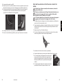
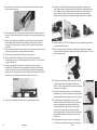
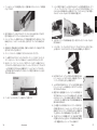
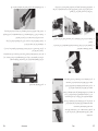
6. Ensure the arm retaining clip is open.
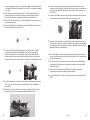
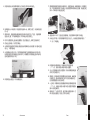
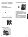
7. Remove the arm tube (wand) from the box. With one hand, gently grip the arm
tube and support the 5-pin plug for safety.
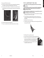
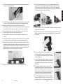
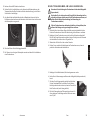
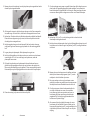
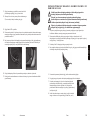
8. Whilst holding the ying lead and
5-pin connector clear, carefully
position the recess on the
underside of the arm carrier over
and on to the bearing seat
ensuring it self locates. Do not
allow it to ‘drop’.
9. Swing the arm tube into the rest
and lock in place by closing the
arm clip.
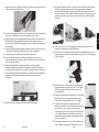
10. Ease the 5-pin plug in to the
socket being careful not to
misalign the pins. The cable
should be arranged in an arc.
11. Remove the counterweight from the box and slide
over the counter weight peg at the rear of the arm
12. Slide fully forward and nip the grub screw up using
the 2.5mm allen key
32 roksan.com
ENGLISH
Sara

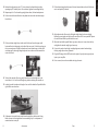
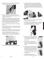
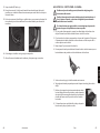
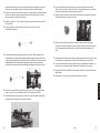
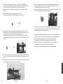
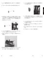
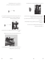
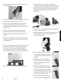
13. Remove the HDC cable from the box
14. Fit the 5-pin socket to the base of the arm from underneath the turntable taking
care to align it correctly to avoid damaging the pins in the arm base
15. At the same end of the cable there is an earth lead, this is connected to the earth
terminal located next to the arm base again this is done from the underside of the
turntable
16. Dress/secure the cable in place as appropriate
17. The arm is now installed on the turntable and ready to receive a cartridge
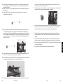
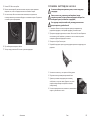
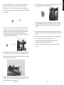
TO FIT A CARTRIDGE TO THE SARA:
Establish the correct tracking weight (down-force) from the cartridge’s
instructions
Decide whether you wish to t the optional nger lift (supplied with the
Sara) when tting the cartridge and select the correct length of bolt
(supplied with cartridge)
If the cartridge has a removable stylus, it is recommended that as much of
the tting process is done with it removed
1. With a pair of small pliers, connect the wires under the head shell to the cartridge
pins taking care to match the colours together
2. Fix the cartridge to the head shell starting with the bolt on the left. If you’re
choosing to use the nger lift, t at this stage on the top side of the head shell –
nger tighten
3. Repeat step 2 for the bolt on the right
4. To start with, line the front of the cartridge up so its front edge is parallel with the
front edge of the head shell
5. Ret the stylus if it was previously removed
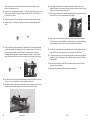
6. Get some scales ready to measure the tracking weight (down-force)
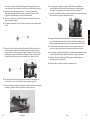
7. Slide the counterweight back about half way by loosening
the grub screw and release the arm retaining clip ensuring
that the arm lift lever is in the up position (pushed back)
8. If the turntable has a mat, remove it and place the scales on
to the platter and set them at ‘zero’
54
ENGLISH
roksan.com Sara

9. Move the arm (and cartridge) over the correct place on the scales to be weighed
and lower the cartridge on to the scales
10. If the weight is too much, raise the arm and slide the counterweight back a little. If
it is too light, slide the counterweight forward a little
11. Repeat the step 10 until the cartridge manufacturer’s recommended tracking
weight (down-force) is achieved and then return the arm to its rest and close the
arm retaining clip and nip the grub screw up on the counterweight
12. Remove the scales but keep to hand as they will be required again and replace the
mat on to the platter if it was previously removed
13. Put a record on the turntable. Do not turn the turntable on yet
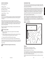
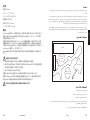
14. Remove the arm alignment protractor from the arm box and gently lower the
arm and cartridge on to the record about 1 or 2 cm’s from the beginning without
switching the turntable on
15. Look across the turntable/arm/cartridge from the right and with the alignment
protractor help up parallel along its length behind the arm on the record, check if
the arm tube is parallel with the horizontal lines on the alignment protractor. The
arm needs to be parallel to the horizontal lines on the alignment protractor and
therefore with the record when it is being played.
16. Return the arm to its rest and close the arm retaining clip
17. To adjust the arm height and to achieve it being parallel when playing a record,
hold the bearing seat/arm lift assembly plate (not the arm carrier) and loosen the
two grub screws in the arm collar and raise or lower the pillar of the assembly as
required and then secure in place by nipping up one of the arm collar’s grub screws
18. Repeat steps 15, 16 and 17 until the correct height is achieved and then tighten
both grub screws in the arm collar
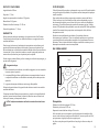
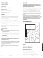
19. Remove the record from the turntable and place the alignment protractor at on
the mat/platter with the spindle through the hole in the protractor (point ‘O’)
printed side up
20. Bring the arm and cartridge across the protractor and lower
on to the outer of the alignment grids (point ‘C’) with the
stylus tip falling inside the small circle in the middle of the
grid.
21. The cartridge and arm’s front edges should be parallel to
each other and parallel within the grid when the stylus tip is
within the small circle when viewed from above
22. To adjust, loosen the cartridge bolts and slide backwards
or forwards as required ensuring that before each
measurement, the cartridge and arms front edges are
parallel to each other and the cartridge bolts are nipped
up – this may need to be repeated a few times to achieve
correct alignment
23. Once achieved, bring the arm and cartridge across the
protractor and lower on to the inner of the alignment grids
(point ‘D’) with the stylus tip falling inside the small circle in
the middle of the grid and repeat step 22 to achieve correct
alignment
76
ENGLISH
roksan.com Sara

24. Recheck the alignment at point ‘C’. Get as close to the ideal at both points by
repeating step 22 at both points. Once achieved, tighten the cartridge bolts up
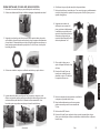
25. Repeat steps 8 to 11 as the tacking weight (down-force) will need readjustment
26. Put the mat and the record back on the platter and remove the anti-skate weight
from the box
27. Fit the anti-skate weight’s loop (at the end of the thread) over the upper small
horizontal bar (anti-skate peg) on the side of the arm carrier. Push the loop along to
the inner most groove. Drape the thread over the anti-skate hanger in front of the
anti-skate peg so that weight hangs freely and rises as the arm travels towards the
centre of a record
28. To check the azimuth of the arm, gently lower the arm and cartridge on to the
record about 1 or 2 cm’s from the beginning without switching the turntable on
29. Looking from the front down the length of arm see if the head shell is parallel left to
right with the record surface
30. If adjustment is required, remove the Azimuth weight from the box and its bag.
Return the arm to its rest and close the arm retaining clip. If no adjustment is
needed continue to step 34
31. Fit the Azimuth weight to the lower of the two horizontal bars on the left of the arm
carrier
and push fully inboard.
32. Adjust the azimuth of the arm by sliding the weight along the bar accordingly.
Recheck by moving the arm back on to the record to see if it is now parallel. Repeat
this until the head shell is parallel with the record.
33. When the head shell is parallel left to right, return the arm to its rest, close the clip
and tighten the azimuth weight’s grub screw up
34. If you wish to recheck arm height, cartridge alignment, azimuth and cartridge
tracking weight (down-force), please do
35. Plug the RCA plugs of the HDC lead in to the inputs of your phono stage or phono
input on your amplier
36. Put on a record, turn on the turntable and enjoy the music
98
ENGLISH
roksan.com Sara

SPECIFICATIONS
Effective Length: 240 mm
Overhang: 17.5 mm
Headshell Offset Angle: 22.9 degrees
Effective Mass: 24.2 grams
Mounting Hole Diameter: 23 - 25 mm
Armboard Thickness: 7 - 26 mm
WARRANTY
There are no user-serviceable parts inside your Sara Tonearm. If a fault should develop,
refer any servicing to your appointed Roksan dealer, distributor or Roksan approved
service agent.
Both the craftsmanship and the performance of this product is covered by the
manufacturer’s warranty against manufacturing defects provided that the product was
supplied by an authorised Roksan retailer under the consumer sale agreement. For the
period of cover please refer to the product page on our website: roksan.com for the
product you have purchased.
When purchasing Roksan products, please keep your receipt of purchase safe, as this
validates your warranty.
This warranty excludes:
1. Damage caused due to accident, misuse, neglect and incorrect installation,
adjustment or repair.
2. Liability for damage or loss during transit from the retailer or purchaser to Roksan
or its authorised distributor for the purposes of repair or inspection.
3. Carriage costs to Roksan that will be borne by the consignor.
All claims under this warranty must be made through an authorised Roksan retailer.
If equipment returned for repair to Roksan is found on inspection to not comply with the
product specication, Roksan reserves the right to make a charge for examination and
return carriage.
NOTE: Unauthorised servicing will void this warranty.
INTRODUCTION
Le Sara a été conçu pour élever les performances à un niveau inégalé. Une fois installé
sur une platine de haute qualité, le Sara permet d’obtenir les meilleures performances à
partir de n’importe quelle cellule.
Les meilleurs composants, matériaux et processus de fabrication ont été sélectionnés.
La conception unipivot du Sara, doté d’un porte-cellule et d’une broche en carbure
de tungstène, permet de minimiser la friction et d’optimiser la liberté de mouvement.
Le réglage de l’azimut est indépendant du contrepoids principal. Le câblage interne
est OFC argenté de haute qualité et notre câble externe HDC de haute qualité est
standard. Ces caractéristiques de conception rendent possible une performance
incolore, dynamique, transparente et musicale.
Le Sara n’offre pas seulement une superbe qualité sonore et un fonctionnement sans
défaut. Il est également l’accessoire idéal pour les platines et les cellules Roksan, et
offre une compatibilité avec ceux des autres fabricants. Tous les réglages ont été prévus
pour s’effectuer facilement et pour rester en place pour une performance régulière et la
tranquillité de l’utilisateur.
DANS LA BOÎTE
Cables
Counter-
Weight
Accessories
Arm
Arm Collar
& Lock Nut
Arm Carrier
Prérequis
Diamètre requis du trou de montage: 23-25mm
Distance entre le pivot et l’axe de rotation: 222,5mm
Épaisseur de la plaque du bras: 25mm max.
En cas de déplacement ou de transport de la platine une fois le Sara installé, veuillez
retirer le tube du bras (tige) pour prévenir tout dommage, car le bras n’est pas xé mais
tient en place sous l’effet de son propre poids.
Un disque supposé aussi plat que possible pour aligner le bras de lecture et la tête de
lecture.
FRANCAIS
1110 roksan.com Sara

MONTAGE DU SARA SUR LA PLATINE
1. Sortir le collier de bras et l’écrou de xation du collier de bras de la boîte.
2. Déposer délicatement le collier de bras dans le trou de montage par le haut
3. Tout en maintenant le collier en place, xer l’écrou du collier de bras par dessous
de façon à ce que l’arête de l’écrou soit en contact avec la plaque de bras et serrer
délicatement à la main. Il est recommandé de placer les deux trous des vis sans tête
approximativement aux positions 11h et 2h lorsque vous regardez la platine de fac.
4. Déposer doucement l’ensemble dans le trou du collier de bras par le haut
5. Le soulever en laissant un espace de 5 à 6mm entre celui-ci et le collier. Aligner
l’ensemble pour qu’il pointe vers l’avant de la platine avec le levier relève-bras sur
la droite. Avec la clé Allen de 3 mm fournie, serrer les vis sans tête sur le côté du
collier de bras.
6. S’assurer que l’attache de xation du bras est ouverte.
7. Sortir le tube du bras (tige) de la boîte. D’une main, saisir délicatement le tube du
bras près du support de bras et tenir la prise à 5 broches pour plus de sécurité.
8. Tout en maintenant de côté le l et
le connecteur à cinq broches,
positionner délicatement la cavité
sous le support de bras au dessus
du siège de pallier, en vous
assurant de bien avoir réalisé
l’assemblage. Ne pas le laisser
«tomber».
9. Pivoter le tube du bras jusqu’au
repose-bras et le verrouiller avec
l’attache de bras.
10. Brancher le connecteur à cinq
broches dans la prise, en prenant
soin de bien aligner les broches.
Le câble doit être disposé en arc
de cercle.
11. Sortir le contrepoids de la boîte et l’enler sur l’ergot
de contrepoids à l’arrière du bras
12. Faire coulisser complètement vers l’avant et serrer la
vis sans tête avec la clé Allen de 2,5 mm
FRANCAIS
1312 roksan.com Sara

13. Sortir le câble HDC de la boîte
14. Brancher le connecteur 5 broches à la base du bras depuis le dessous de la platine,
en prenant garde de l’aligner correctement pour éviter d’endommager les broches
dans la base du bras.
15. À la même extrémité du câble se trouve le l de masse, qui doit être raccordé à la
borne de masse située à côté de la base du bras. Le branchement est à effectuer
également depuis le dessous de la platine
16. Mettre le câble bien en place pour le sécuriser
17. Le bras est à présent installé sur la platine, prêt pour l’installation d’une cellule
POUR INSTALLER UNE CELLULE SUR LE SARA:
Réaliser le réglage de la force d’appui correcte (force verticale) selon les
instructions de la cellule
Décider si vous souhaitez installer le relève-bras en option (fourni avec le
Sara) lors du montage de la cellule et sélectionner la longueur de boulon
requise (fourni avec la cellule)
Si la cellule comporte un stylus amovible, il est recommandé de procéder
autant que possible au montage avec le stylus retiré
1. Avec une petite pince, connecter les ls sous la tête de lecture aux broches de la
cartouche, en s’assurant de bien faire correspondre les couleurs.
2. Fixer la cellule à la tête de lecture en commençant par le boulon de gauche. Si
vous décidez d’utiliser le relève-bras, le monter maintenant sur le côté supérieur de
la tête de lecture, et serrer à la main.
3. Répéter l’étape 2 pour le boulon de droite.
4. Pour commencer, aligner l’avant de la cellule pour que l’arête avant soit parallèle à
l’arête avant de la tête de lecture.
5. Replacer le stylus s’il avait été retiré.
6. Préparez une balance an de mesurer la force d’appui (force verticale).
7. Faire coulisser le contrepoids vers l’arrière jusqu’à mi-course
en desserrant la vis sans tête, et défaire l’attache de xation
du bras, en vous assurant que le levier relève-bras est en
position relevée (poussé en arrière).
8. Si la platine comporte un tapis, le retirer, puis placer la
balance sur le plateau et la réinitialiser.
FRANCAIS
1514 roksan.com Sara

9. Placer le bras (et la cellule) au bon endroit de la balance pour procéder à la pesée,
et abaisser la cellule sur la balance.
10. Si le poids est trop important, relever le bas et déplacer légèrement le contrepoids
vers l’arrière. S’il est trop faible, déplacer légèrement le contrepoids vers l’avant.
11. Répéter l’étape 10 jusqu’à parvenir à la force d’appui (force verticale)
recommandée par le fabricant de la cellule, puis replacer le bras sur le repose-bras,
fermer l’attache de xation du bras et serrer la vis sans tête sur le contrepoids.
12. Mettre de côté la balance mais la conserver à portée de main car elle servira à
nouveau. Replacer le tapis sur le plateau s’il avait été retiré.
13. Placer un disque sur la platine. Ne pas mettre la platine sous tension pour le
moment.
14. Sortir le gabarit d’alignement de la boîte et abaisser délicatement le bras et la cellule
sur le disque à environ 1 ou 2cm du début, sans mettre la platine sous tension
15. Regarder en direction de la platine/du bras/de la cellule depuis le côté droit, et, en
maintenant le gabarit d’alignement parallèle sur sa longueur derrière le bras, sur le
disque, vérier que le tube du bras est parallèle avec les lignes horizontales sur le
gabarit d’alignement. Le bras doit être parallèle avec les lignes horizontales sur le
gabarit d’alignement et donc avec le disque lors de sa lecture.
16. Replacer le bras sur le repose-bras et fermer l’attache de xation du bras.
17. Pour ajuster la hauteur du bras, et pour qu’il soit parallèle au disque lors de la
lecture, maintenir le siège de pallier/plaque d’assemblage du relève bras (pas le
support du bras), desserrer ensuite les deux vis sans tête du collier du bras, puis
élever ou abaisser le pilier de l’ensemble au besoin, puis bloquer en serrant une vis
du collier lorsque la bonne position est atteinte.
18. Répéter les étapes 15, 16 et 17 jusqu’à parvenir à la hauteur correcte, puis resserrer
les deux vis du collier de bras.
19. Enlever le disque de la platine, et placer le gabarit d’alignement à plat sur le tapis/
plateau, l’axe de rotation passant par le trou du gabarit (point «O»), côté imprimé
vers le dessus.
20. Amener le bras et la cellule au dessus du gabarit, et
l’abaisser sur l’extérieur des grilles d’alignement (point
«C»), de façon à ce que la pointe du stylus soit dans le trou
au milieu de la grille.
21. Lorsque vous les regardez depuis le dessus, la cellule et les
arêtes avant du bras doivent être parallèles entre elles et
avec la grille lorsque la pointe du stylus se trouve dans le
petit cercle
22. Pour effectuer le réglage, desserrer les boulons de la
cellule et la faire coulisser vers l’avant ou l’arrière tel que
nécessaire, en s’assurant avant chaque mesure que les
arêtes avant de la cellule et du bras soient parallèles entre
elles et que les boulons de la cellule soient resserrés - la
procédure devra être répétée plusieurs fois au besoin.
23. Une fois le réglage effectué, amener le bras et la cellule
au dessus du gabarit et l’abaisser sur l’intérieur des grilles
d’alignement (point «D»), de façon à ce que la pointe du
FRANCAIS
1716 roksan.com Sara

stylus soit dans le trou au milieu de la grille, puis recommencer l’étape 22 pour
parvenir à l’alignement correct.
24. Vérier de nouveau l’alignement au point «C». Répéter l’étape 22 jusqu’à parvenir
aussi près que possible du réglage idéal pour les deux points. Ceci fait, resserrer
les boulons de la cellule.
25. Répéter les étapes 8 à 11 pour régler à nouveau la force d’appui (force verticale).
26. Replacer le tapis et le disque sur le plateau, et retirer le poids antipatinage de la
boîte
27. Enler la boucle du poids antipatinage (à l’extrémité du l) sur la barre horizontale
supérieure (ergot de l’antipatinage) sur le côté du support de bras. Faire coulisser
la boucle jusqu’à l’encoche la plus à l’intérieur. Faire passer le l par dessus la
suspension antipatinage devant l’ergot antipatinage, de façon à ce que le poids
pende librement et s’élève lorsque le bras se déplace vers l’intérieur d’un disque
28. Pour vérier l’azimut du bras, baisser délicatement le bras et la cellule sur le disque
à environ 1 ou 2cm du début, sans mettre la platine sous tension.
29. En regardant depuis l’avant du bras dans la direction de sa longueur, vérier que la
tête de lecture est parallèle de gauche à droite avec la surface du disque
.
30. Si un réglage est nécessaire, sortir le poids d’azimut de la boîte et de son sac.
Replacer le bras sur le repose-bras et fermer l’attache de xation du bras. Si aucun
réglage n’est nécessaire, passer à l’étape 34
31. Enler le poids d’azimut sur la barre horizontale la plus basse à gauche du support
de bras
et le faire coulisser complètement vers l’intérieur.
32. Régler l’azimut du bras en faisant coulisser le poids sur la barre en conséquence.
Contrôler de nouveau le parallélisme en replaçant le bras sur le disque. Répéter la
procédure jusqu’à ce que la tête de lecture soit parallèle avec le disque.
33. Une fois que la tête de lecture est parallèle de gauche à droite, replacer le bras sur
le repose-bras, fermer l’attache et serrer la vis sans tête du poids d’azimut.
34. À ce stade, vous pouvez si vous le souhaitez contrôler de nouveau les réglages de
la hauteur du bras, de l’alignement de la cellule, de l’azimut et de la force d’appui
(force verticale)
35. Brancher les prises RCA du câble HDC aux entrées de votre phono ou entrées
phono de votre amplicateur
36. Mettez un disque, allumez la platine et appréciez la musique
FRANCAIS
1918 roksan.com Sara

SPÉCIFICATIONS
Longueur effective: 240mm
Avance: 17,5mm
Angle de décalage de la tête de lecture: 22,9 degrés
Poids effectif: 24.2 grammes
Diamètre du trou de montage: 23 - 25mm
Épaisseur de la plaque de bras: 7 - 26mm
GARANTIE
Votre bras de lecture Sara ne contient aucune pièce réparable par l’utilisateur. Dans
l’éventualité d’apparition d’une panne, veuillez vous référer pour toute réparation à
votre revendeur/distributeur Roksan attitré ou à un revendeur agréé par Roksan.
La qualité de fabrication et les performances de ce produit sont couvertes par la
garantie du fabricant contre les défauts de fabrication, dans la mesure où le produit a
été fourni par un revendeur Roksan agréé selon un accord de vente. Pendant la période
de garantie, reportez-vous à la page relative au produit que vous avez acheté sur notre
site web : roksan.com
Lors de l’achat de produits Roksan, conservez précieusement votre preuve d’achat,
celle-ci faisant ofce de bon de garantie.
La garantit ne couvre pas :
1. Les dommages survenus suite à un accident, à une utilisation inadéquate, à une
négligence ou installation incorrecte, à une modication ou à une réparation.
2. La responsabilité liée aux dommages ou les pertes occasionnés durant le transit
depuis le revendeur ou l’acheteur jusqu’à Roksan ou son distributeur agréé pour
réparation ou inspection.
3. Les frais de port jusqu’à Roksan, qui sont à la charge de l’expéditeur.
Toutes les réclamations relatives à cette garantie doivent être effectuées auprès d’un
revendeur Roksan agréé.
Dans le cas où l’équipement retourné pour réparation à Roksan est désigné lors de
l’inspection non conforme aux spécications du produit, Roksan se réserve le droit de
facturer la vérication et le transport du produit.
REMARQUE : Toute réparation non autorisée invalide la garantie.
INTRODUZIONE
Il braccio Sara è stato sviluppato per far salire le prestazioni a nuovi livelli. Se installato
su un giradischi di qualità elevata, il Sara consente di ottenere le migliori prestazioni
indipendentemente dalla testina scelta.
Sono stati selezionati i migliori componenti, materiali e processi di fabbricazione
possibili. Il braccio Sara è stato realizzato con un design unipivot, utilizzando una sede
in pietra preziosa e un perno in carburo di tungsteno per ridurre al minimo l’attrito e
lasciare la massima libertà di movimento. La regolazione dell’azimut è separata dal
contrappeso principale. Il cablaggio interno è OFC placcato argento di alta qualità e
il cavo esterno HDC di alta qualità è di serie. Queste caratteristiche di progettazione
consentono prestazioni equilibrate, dinamiche, trasparenti e musicali.
Sara non si limita a offrire una qualità del suono eccezionale e un funzionamento
senza problemi. Sara rappresenta il punto d’incontro perfetto tra i giradischi e le
testine Roksan ed è compatibile anche con quelle realizzate da altri produttori. Tutte
le regolazioni sono state progettate per risultare semplici e restare stabili, in modo da
garantire prestazioni uniformi e maggior tranquillità
NELLA SCATOLA
Cables
Counter-
Weight
Accessories
Arm
Arm Collar
& Lock Nut
Arm Carrier
Prerequisiti
Diametro del foro di montaggio: 23-25 mm
Distanza tra perno e mandrino: 222,5 mm
Spessore materiale del supporto per braccio: 25 mm max
Qualora sia necessario spostare o trasportare il giradischi dopo l’installazione del
braccio Sara, per evitare danneggiamenti è necessario rimuovere il tubo del braccio
(bacchetta), perché quest’ultimo non è ssato ma resta in posizione sotto il proprio peso
Un disco che sia il più piatto possibile per allineare braccio e portatestina.
ITALIA
2120 roksan.com Sara

PER INSTALLARE SARA SUL GIRADISCHI:
1. Prendere dalla scatola il collare del braccio e l’apposito dado di ssaggio
2. Con delicatezza, calare dall’alto il collare del braccio attraverso il foro di montaggio
3. Mantenendo il collare in posizione, montare il dado del collare del braccio da sotto
in modo che la parte sporgente dal dado si inserisca nel supporto del braccio e
serrare manualmente con delicatezza. Fare in modo che, guardando dalla parte
anteriore del giradischi, i due fori per viti senza testa posti sul lato restino
posizionati a ore 11 e ore 2.
4. Con delicatezza, lasciar cadere dall’alto il gruppo nel foro presente sul collare del braccio
5. Sollevarlo in modo da lasciare uno spazio di 5 o 6 mm tra di esso e il collare.
Allineare il gruppo in modo che sia rivolto verso la parte anteriore del giradischi, con
la levetta per il sollevamento del braccio posta sulla destra. Con la chiave a brugola
in dotazione da 3 mm, serrare le viti senza testa poste sul lato del collare del braccio.
6. Assicurarsi che la graffa di bloccaggio del braccio sia aperta.
7. Prendere dalla scatola il tubo del braccio (bacchetta). Con una mano, afferrare
delicatamente il tubo del braccio vicino al portabraccio e sostenere il connettore a
5 poli, per sicurezza.
8. Tenendo liberi il cavo volante e il
connettore a 5 pin, posizionare
con cura l’incavo sul lato inferiore
del portabraccio sulla sede del
cuscinetto, assicurandosi che si
posizioni da sé. Non lasciare che
“cada”.
9. Far oscillare il tubo del braccio sul
supporto e bloccarlo in posizione
chiudendo la graffa del braccio.
10. Inserire il connettore a 5 pin nella
presa prestando attenzione a non
disallineare i pin. Il cavo deve
essere disposto ad arco.
11. Prendere dalla scatola il contrappeso e far scorrere
sul distanziatore del contrappeso sulla parte
posteriore del braccio
12. Far scorrere completamente in avanti e serrare la vite
senza testa con la chiave a brugola da 2,5 mm
ITALIA
2322 roksan.com Sara

13. Prendere dalla scatola il cavo HDC
14. Montare la presa a 5 pin alla base del braccio da sotto il giradischi, avendo cura di
allinearla correttamente per evitare di danneggiare i pin della base del braccio
15. Alla stessa estremità del cavo è presente un conduttore di terra da collegare al
morsetto di terra che si trova accanto alla base del braccio: anche questa
operazione viene effettuata da sotto al giradischi
16. Avvolgere/assicurare il cavo in posizione in modo appropriato
17. Il braccio è ora installato sul giradischi e pronto per l’inserimento di una testina
PER INSTALLARE UNA TESTINA SUL BRACCIO
SARA:
Stabilire il peso di lettura corretto (forza di tracciamento) in base alle
istruzioni della testina
Decidere se si desidera montare il nger lift opzionale (in dotazione con
Sara) durante il montaggio della testina e scegliere il bullone della
lunghezza corretta (in dotazione con la testina)
Se la testina è dotata di uno stilo rimovibile, si raccomanda di eseguire la
maggior parte del processo di montaggio con lo stilo rimosso
1. Con delle piccole pinze, collegare i cavi sotto il portatestina ai pin della testina,
avendo cura di far corrispondere i colori
2. Fissare la testina al portatestina, iniziando dal bullone a sinistra. Se si decide di
utilizzare il nger lift, inserirlo ora sul lato superiore del portatestina e serrare
manualmente
3. Ripetere il passo 2 per il bullone sulla destra
4. Per iniziare, allineare la parte anteriore della testina in modo che il suo bordo
anteriore sia parallelo al bordo anteriore del portatestina
5. Riposizionare lo stilo se è stato rimosso in precedenza
6. Preparare delle bilancine per tarare il peso di lettura (forza di tracciamento)
7. Far scorrere indietro il contrappeso no a metà circa del
percorso, allentando la vite senza testa e sganciando la
graffa di bloccaggio del braccio; assicurarsi che la leva di
sollevamento del braccio sia in posizione rialzata (spinta
indietro)
8. Se il piatto girevole dispone di un tappetino, rimuoverlo,
posizionare le bilancine sul piatto e metterle a ‘zero’
ITALIA
2524 roksan.com Sara

9. Spostare il braccio (e la testina) sulle bilancine in posizione corretta per la pesatura
e abbassare la puntina sulle bilancine
10. Se il peso è eccessivo, sollevare il braccio e far scorrere un po’ indietro il contrappeso.
Se il peso non è sufciente, far scorrere il contrappeso un po’ in avanti
11. Ripetere il passo 10 no al raggiungimento del peso di lettura raccomandato dal
fabbricante della testina (forza di tracciamento), quindi riportare il braccio sul
supporto, chiudere la graffa di bloccaggio del braccio e stringere la vite senza testa
del contrappeso
12. Rimuovere le bilancine tenendole però a portata di mano perché serviranno ancora
e riposizionare il tappetino sul piatto se è stato rimosso in precedenza
13. Posizionare un disco sul piatto. Evitare di far girare il giradischi
14. Prendere dalla scatola del braccio la dima per l’allineamento del braccio e
abbassare delicatamente il braccio e la testina sul disco a circa 1 o 2 cm dall’inizio
senza accendere il giradischi
15. Guardando il giradischi/braccio/testina da destra, trovare la posizione di
allineamento del braccio per tutta la sua lunghezza con la dima di allineamento
posizionata sul disco dietro il braccio e controllare se il tubo del braccio è parallelo
alle linee orizzontali sulla dima di allineamento. Il braccio deve essere parallelo alle
linee orizzontali sulla dima di allineamento e quindi con il disco durante la
riproduzione.
16. Riportare il braccio sul supporto e chiudere la graffa di bloccaggio
17. Per regolare l’altezza del braccio in modo che si trovi in posizione parallela al disco
durante la riproduzione, afferrare la piastra del gruppo sede del cuscinetto/
sollevamento del braccio (non il supporto del braccio), allentare le due viti senza
testa nel collare del braccio e sollevare o abbassare la colonna del gruppo secondo
necessità, quindi ssare in posizione serrando una delle viti senza testa nel collare
del braccio
18. Ripetere i passi 15, 16 e 17 no a raggiungere l’altezza corretta, quindi serrare
entrambe le viti senza testa nel collare del braccio
19. Rimuovere il disco dal giradischi e posizionare la dima di allineamento in piano sul
tappetino/piatto con il mandrino nel foro della dima (punto ‘O’) con il lato stampato
rivolto verso l’alto
20. Muovere il braccio e la testina sulla dima e abbassarli sulla
griglia di allineamento più esterna (punto ‘C’) con la punta
dello stilo posizionata all’interno del piccolo cerchio al
centro della griglia
21. Quando la punta dello stilo, vista dall’alto, si trova all’interno
del piccolo cerchio, i bordi anteriori della testina e del
braccio devono essere paralleli tra loro e con la griglia
22. Per effettuare la regolazione, allentare i bulloni della
testina e far scorrere in avanti o indietro secondo necessità,
assicurandosi che, prima di ogni misurazione, i bordi
anteriori della cartuccia e del braccio siano paralleli tra loro
e che i bulloni della testina siano allentati; per ottenere il
corretto allineamento, potrebbe essere necessario ripetere
più volte la procedura
23. Dopo la regolazione, muovere il braccio e la testina sulla
dima e abbassare sulla griglia di allineamento più interna
ITALIA
2726 roksan.com Sara

(punto ‘D’) con la punta dello stilo posizionata all’interno del piccolo cerchio al
centro della griglia, quindi ripetere il passo 22 per trovare l’allineamento corretto
24. Vericare di nuovo l’allineamento sul punto ‘C’. Avvicinarsi il più possibile
all’allineamento perfetto, ripetendo il passo 22 in entrambi i punti. Una volta
raggiunto il risultato desiderato, serrare i bulloni della testina
25. Ripetere i punti da 8 a 11, poiché il peso di lettura (forza di tracciamento) dovrà
essere nuovamente regolato
26. Riposizionare il tappetino e il disco sul piatto e rimuovere il peso antiskating dalla
scatola
27. Montare l’occhiello del peso antiskating (all’estremità del lo) sulla piccola barra
orizzontale superiore (distanziatore antiskating) posta sul lato del portabraccio.
Spingere l’anello no alla scanalatura più interna. Sistemare il lo sopra il gancio
antiskating posto davanti al distanziatore antiskating, in modo che il peso penda
liberamente e si sollevi quando il braccio si sposta verso il centro di un disco
28. Per controllare l’azimut del braccio, abbassare delicatamente quest’ultimo e la
testina sul disco a circa 1 o 2 cm dall’inizio senza accendere il giradischi
29. Guardando dalla parte anteriore verso il basso la lunghezza del braccio, vedere se il
portatestina, da sinistra a destra, è parallelo alla supercie del disco
30. Se è necessaria una regolazione, prendere dalla scatola il peso dell’azimut
rimuoverlo dalla busta. Riportare il braccio sul supporto e chiudere la graffa di
bloccaggio. Se la regolazione non è necessaria, continuare dal passo 34
31. Montare il peso dell’azimut sulla parte inferiore delle due barre orizzontali a sinistra
del portabraccio
e spingere completamente a fondo.
32. Regolare l’azimut del braccio facendo scorrere di conseguenza il peso lungo la
barra. Ricontrollare spostando di nuovo il braccio sul disco per vedere se è ora
parallelo. Ripetere l’operazione no a quando il portatestina è parallelo al disco.
33. Quando il portatestina è parallelo da sinistra a destra, riportare il braccio sul
supporto, chiudere la graffa e serrare la vite senza testa del peso dell’azimut
34. Se si desidera ricontrollare l’altezza del braccio, l’allineamento della testina, l’azimut
e il peso di lettura della testina (forza di tracciamento), si prega di procedere
35. Collegare i connettori RCA del cavo HDC agli ingressi dello stadio phono o
all’ingresso phono sull’amplicatore
36. Mettere un disco, accendere il giradischi e godersi la musica
ITALIA
2928 roksan.com Sara

SPECIFICHE TECNICHE
Lunghezza effettiva: 240 mm
Rimbombo: 17,5 mm
Angolo di offset del portatestina: 22,9 gradi
Massa effettiva: 24.2 grammi
Diametro foro di alloggiamento: 23 - 25 mm
Spessore della base del braccio: 7 - 26 mm
GARANZIA
All’interno del braccio di lettura Sara non sono presenti parti riparabili dall’utente.
Qualora dovesse vericarsi un guasto, per qualsiasi intervento di assistenza rivolgersi al
concessionario, al distributore o all’agente di assistenza autorizzato da Roksan.
Sia la struttura che le prestazioni di questo prodotto sono coperte dalla garanzia del
produttore contro i difetti di fabbricazione, posto che il prodotto sia stato fornito da un
rivenditore autorizzato Roksan con contratto di vendita. Durante il periodo di garanzia,
per il prodotto acquistato si prega di fare riferimento alla pagina di prodotto sul sito
Web roksan.com
Quando si acquistano prodotti Roksan, si prega di conservare al sicuro la ricevuta
d’acquisto, necessaria per convalidare la garanzia.
La presente garanzia esclude:
1. danni causati da incidenti, uso improprio, negligenza oppure da installazione,
regolazione o riparazione non corrette;
2. responsabilità per danni o perdite durante il trasporto dal rivenditore o
dall’acquirente a Roksan o al suo distributore autorizzato per la riparazione o
l’ispezione;
3. spese di trasporto a Roksan che saranno a carico del mittente.
Tutti i diritti di garanzia devono essere fatti valere presso un rivenditore autorizzato
Roksan.
Qualora l’apparato restituito a Roksan per la riparazione risulti non conforme alle
speciche di prodotto a seguito dell’ispezione, Roksan si riserva il diritto di addebitare
un corrispettivo per la verica e per il trasporto di restituzione.
NOTA: interventi di assistenza non autorizzati rendono nulla la presente
garanzia.
EINLEITUNG
Der Sara wurde entwickelt, um Leistungsfähigkeit auf ein neues Niveau zu bringen. Wird
er an einem qualitativ hochwertigen Plattenspieler montiert, ermöglicht der Sara beste
Performance für jeden gewählten Tonabnehmer.
Es wurden die bestmöglichen Komponenten, Materialien und Herstellungsprozesse
verwendet. Für minimale Reibung und maximale Bewegungsfreiheit verwendet der
Sara ein Einpunktlager-Design mit Juwelzapfen und Wolframcarbid-Nadel. Azimut-
Justierung erfolgt unabhängig vom Hauptgegengewicht. Die interne Verdrahtung
besteht aus hochwertigem versilbertem OFC und unser hochwertiges, externes
HDC-Kabel ist Standard. Diese Konstruktionselemente liefern ein unverfälschtes,
dynamisches, transparentes musikalisches Erlebnis.
Der Sara bietet nicht nur überragende Klangqualität und problemlose Bedienung. Er
passt auch perfekt zu den Plattenspielern und Tonabnehmern von Roksan und ist zudem
mit denen anderer Hersteller kompatibel. Alle Justierungen wurden so entwickelt,
dass sie leicht durchzuführen sind und sicher eingestellt bleiben, um konsistente
Performance und Zufriedenheit zu gewähren.
LIEFERUMFANG
Cables
Counter-
Weight
Accessories
Arm
Arm Collar
& Lock Nut
Arm Carrier
Voraussetzungen
Benötigter Durchmesser des Aufnahmebohrung: 23-25mm
Abstand von Tonarmlager zum Tellerlager: 222,5mm
Tonarmbrett-Materialdicke: max. 25mm
Falls der Plattenspieler nach der Montage des Sara bewegt oder transportiert werden
muss, nehmen Sie das Tonarmrohr ab, um Schaden zu vermeiden, da dieses nicht fest
verbunden ist, sondern durch sein eigenes Gewicht auiegt.
Eine möglichst plane Schallplatte, um Tonarm und Headshell auszurichten.
DEUTSCH
3130 roksan.com Sara

SARA AUF DEM PLATTENSPIELER EINSETZEN:
1. Nehmen Sie die Tonarmbasis und die Basis-Befestigungsmuttern aus dem Karton.
2. Senken Sie die Tonarmbasis behutsam von oben durch die Aufnahmebohrung.
3. Während Sie die Basis in Position halten, bringen Sie die Befestigungsmuttern
von unten so an, dass der Rücken der Mutter plan am Tonarmbrett auiegt, und
ziehen Sie sie handfest an. Es wird empfohlen, dass sich die beiden seitlichen
Gewindestiftlöcher etwa auf 11- und 2-Uhr-Position benden, wenn man von vorne
auf den Plattenspieler blickt.
4. Senken Sie der Tonarmträger behutsam von oben in das Loch in der Armbasis.
5. Heben Sie ihn an, sodass ein Spalt von 5 oder 6mm zwischen Tonarmträger
und Tonarmbasis entsteht. Richten Sie den Tonarmträger so aus, dass er zur
Vorderseite des Plattenspielers mit dem Tonarmlift zur rechten Seite zeigt.
Verwenden Sie den mitgelieferten 3-mm-Inbusschlüssel, um die Gewindestifte an
der Seite der Armbasis festzuziehen.
6. Achten Sie darauf, dass der Tonarm-Halteclip offen ist.
7. Nehmen Sie das Tonarmrohr aus dem Karton. Halten Sie das Tonarmrohr behutsam
mit einer Hand und stützen Sie den 5-poligen Stecker zur Sicherheit.
8. Während Sie das Anschlusskabel
und den 5-poligen Stecker frei
halten, positionieren Sie die
Aussparung an der Unterseite der
Tonarmglocke über und auf dem
Lagerzapfen und stellen Sie sicher,
dass der Arm sich von selbst
ausrichtet. Lassen Sie den Arm
nicht „fallen“.
9. Schwingen Sie das Armrohr in
den Halter und verriegeln Sie ihn
durch Schließen des Halteclips.
10. Führen Sie den 5-poligen Stecker
in die Buchse ein und achten Sie
dabei darauf, die Pole nicht falsch
auszurichten. Das Kabel sollte zu
einem Bogen geformt werden.
11. Nehmen Sie das Gegengewicht aus dem Karton und
schieben Sie es auf den Haltezapfen am hinteren
Ende des Arms.
12. Schieben Sie es komplett nach vorne und
befestigen Sie die Gewindestifte mit dem 2,5-mm-
Inbusschlüssel.
DEUTSCH
3332 roksan.com Sara

13. Nehmen Sie das HDC-Kabel aus dem Karton.
14. Stecken Sie die 5-polige Buchse von der Unterseite des Plattenspielers an den
Tonarmsockel und achten Sie dabei auf die korrekte Ausrichtung, um die Pole im
Sockel nicht zu beschädigen.
15. Am selben Ende des Kabels bendet sich ein Masseleiter, dieser wird mit der
Erdklemme neben dem Armsockel verbunden. Auch dies wird von der Unterseite
des Plattenspielers aus gemacht.
16. Schnüren/Sichern Sie die Kabel gegebenenfalls.
17. Der Tonarm ist nun fertig am Plattenspieler montiert und bereit für die Aufnahme
eines Tonabnehmers.
EINEN TONABNEHMER AM SARA ANBRINGEN:
Entnehmen Sie der Anleitung des Tonabnehmers die korrekte Auagekraft
(Anpressdruck).
Entscheiden Sie, ob sie den optionalen Fingerlift (im Lieferumfang des Sara
enthalten) anbringen möchten, wenn Sie den Tonabnehmer montieren, und
wählen Sie die korrekte Schraubenlänge (im Lieferumfang des
Tonabnehmers enthalten).
Falls der Tonabnehmer eine abnehmbare Nadel hat, wird empfohlen, diese
während der Montage so lange wie möglich zu entfernen.
1. Verbinden Sie mit einer kleinen Zange die Drähte unter dem Headshell mit den
Polen des Tonabnehmers. Achten Sie dabei darauf, gleiche Farben zu verbinden.
2. Befestigen Sie den Tonabnehmer zuerst mit der linken Schraube am Headshell.
Falls Sie den Fingerlift verwenden möchten, bringen Sie ihn jetzt an der Oberseite
der Headshell an und ziehen ihn mit Fingerdruck an.
3. Wiederholen Sie Schritt 2 mit der rechten Schraube.
4. Richten Sie nun zunächst die Vorderkante des Tonabnehmers so aus, dass sie
parallel zur Vorderkante des Headshells ist.
5. Befestigen Sie die Nadel wieder, falls diese abgenommen wurde.
6. Halten Sie eine Tonarmwaage zum Messen der Auagekraft (des Anpressdrucks)
bereit.
7. Schieben Sie das Gegengewicht etwa halb zurück, indem
Sie den Gewindestift lösen, und öffnen Sie den Tonarm-
Halteclip, wobei darauf zu achten ist, dass der Tonarmlift in
Hoch-Position steht (nach hinten gedrückt).
8. Falls der Plattenspieler eine Tellermatte hat, entfernen Sie
diese, platzieren Sie die Waage auf dem Teller und setzen
sie auf „Null“.
DEUTSCH
3534 roksan.com Sara

9. Schieben Sie den Arm (und den Tonabnehmer) über die korrekte Wiegeposition
auf der Waage und senken Sie den Tonabnehmer auf die Waage.
10. Falls das Gewicht zu hoch ist, heben Sie den Arm an und schieben Sie das
Gegengewicht ein wenig nach hinten. Falls das Gewicht zu gering ist, schieben Sie
das Gegengewicht ein wenig nach vorne.
11. Wiederholen Sie Schritt 10, bis die vom Hersteller des Tonabnehmers empfohlene
Auagekraft erreicht ist, schieben Sie den Tonarm danach wieder in den Halter,
schließen Sie den Halteclip und ziehen Sie den Gewindestift am Gegengewicht fest.
12. Entfernen Sie die Waage, aber halten sie weiter griffbereit, da sie später erneut
benötigt wird, und legen Sie gegebenenfalls die Tellermatte wieder auf.
13. Legen Sie eine Schallplatte auf den Plattenspieler. Schalten Sie den Plattenspieler
noch nicht ein.
14. Nehmen Sie die Einstellschablone für den Arm aus dem Karton und senken Sie Arm
und Tonabnehmer behutsam etwa 1 oder 2 cm vom Anfang entfernt auf die Platte,
ohne den Plattenspieler einzuschalten.
15. Blicken Sie von rechts auf den Plattenspieler/Tonarm/Tonabnehmer. Halten Sie die
Einstellschablone parallel entlang der Achse des Tonarms auf die Schallplatte und
prüfen Sie, ob das Armrohr parallel zu den horizontalen Linien auf der
Einstellschablone verläuft. Der Arm muss parallel zu den horizontalen Linien auf
der Schablone und damit auch zur Platte liegen, wenn diese abgespielt wird.
16. Schieben Sie den Tonarm wieder in den Halter und schließen Sie den Halteclip.
17. Um die Armhöhe zu justieren und so zu erreichen, dass der Arm parallel zur
Schallplatte liegt, halten Sie den Tonarmträger mit Lagerzapfen/Armlift (nicht die
Tonarmglocke) fest und lösen Sie die beiden Gewindestifte an der Tonarmbasis. Sie
können den Träger nun wie erforderlich anheben oder absenken. Befestigen Sie ihn
dann in gewünschter Position, indem Sie einen der Gewindestifte an der Tonarmbasis
feststellen.
18. Wiederholen Sie die Schritte 15, 16 und 17, bis die korrekte Höhe erreicht ist, und
ziehen Sie dann beide Stifte der Tonarmbasis fest.
19. Nehmen Sie die Schallplatte vom Plattenspieler und legen Sie die Einstellschablone
ach auf die Matte/den Teller, wobei das Loch in der Schablone in die Spindel
geführt wird (Punkt „O“) und die bedruckte Seite nach oben zeigt.
20. Führen Sie den Arm und Tonabnehmer über die Schablone
und senken sie auf dem äußeren Justagegitter (Punkt „C“)
so ab, dass die Nadelspitze auf den kleinen Kreis in der
Mitte des Gitters fällt.
21. Von oben betrachtet sollten die Vorderkanten des
Tonabnehmers und des Arms parallel zueinander und zum
Gitter liegen, wenn die Nadelspitze innerhalb des kleinen
Kreises liegt.
22. Zum Justieren lösen Sie die Schrauben des Tonabnehmers
und schieben diesen wie nötig vor oder zurück, wobei vor
jeder Messung darauf zu achten ist, dass die Vorderkanten
des Tonabnehmers und des Arms parallel zueinander sind
und die Abnehmerschrauben festgezogen sind – dies muss
eventuell einige Male wiederholt werden, um die korrekte
Justierung zu erreichen.
23. Wenn diese erreicht ist, bewegen Sie den Arm und
Tonabnehmer über die Schablone und senken sie auf dem
DEUTSCH
3736 roksan.com Sara
Seite wird geladen ...
Seite wird geladen ...
Seite wird geladen ...
Seite wird geladen ...
Seite wird geladen ...
Seite wird geladen ...
Seite wird geladen ...
Seite wird geladen ...
Seite wird geladen ...
Seite wird geladen ...
Seite wird geladen ...
Seite wird geladen ...
Seite wird geladen ...
Seite wird geladen ...
Seite wird geladen ...
Seite wird geladen ...
Seite wird geladen ...
Seite wird geladen ...
Seite wird geladen ...
Seite wird geladen ...
Seite wird geladen ...
Seite wird geladen ...
Seite wird geladen ...
Seite wird geladen ...
Seite wird geladen ...
Seite wird geladen ...
Seite wird geladen ...
Seite wird geladen ...
Seite wird geladen ...
Seite wird geladen ...
Seite wird geladen ...
Seite wird geladen ...
Seite wird geladen ...
Seite wird geladen ...
Seite wird geladen ...
Seite wird geladen ...
Seite wird geladen ...
Seite wird geladen ...
Seite wird geladen ...
Seite wird geladen ...
Seite wird geladen ...
Seite wird geladen ...
Seite wird geladen ...
-
 1
1
-
 2
2
-
 3
3
-
 4
4
-
 5
5
-
 6
6
-
 7
7
-
 8
8
-
 9
9
-
 10
10
-
 11
11
-
 12
12
-
 13
13
-
 14
14
-
 15
15
-
 16
16
-
 17
17
-
 18
18
-
 19
19
-
 20
20
-
 21
21
-
 22
22
-
 23
23
-
 24
24
-
 25
25
-
 26
26
-
 27
27
-
 28
28
-
 29
29
-
 30
30
-
 31
31
-
 32
32
-
 33
33
-
 34
34
-
 35
35
-
 36
36
-
 37
37
-
 38
38
-
 39
39
-
 40
40
-
 41
41
-
 42
42
-
 43
43
-
 44
44
-
 45
45
-
 46
46
-
 47
47
-
 48
48
-
 49
49
-
 50
50
-
 51
51
-
 52
52
-
 53
53
-
 54
54
-
 55
55
-
 56
56
-
 57
57
-
 58
58
-
 59
59
-
 60
60
-
 61
61
-
 62
62
-
 63
63


in anderen Sprachen
- français: Roksan Sara Le manuel du propriétaire
- español: Roksan Sara El manual del propietario
- italiano: Roksan Sara Manuale del proprietario
- Nederlands: Roksan Sara de handleiding
- português: Roksan Sara Manual do proprietário
- polski: Roksan Sara Instrukcja obsługi
- 日本語: Roksan Sara 取扱説明書
Andere Dokumente
-
TEAC TN-550 Bedienungsanleitung
-
Thorens TD 206 Benutzerhandbuch
-
Pro-Ject Pro-Ject TT-SG032 The Dark Side of the Moon Limited Edition Turntable Benutzerhandbuch
-
Rotel RP-310 Bedienungsanleitung
-
Lenco Turntable Benutzerhandbuch
-
TEAC TN-400S Bedienungsanleitung
-
-
Thorens TD 160 HD Benutzerhandbuch
-
-
Thorens TD 2030 Benutzerhandbuch