


Alle Rechte vorbehalten. Irrtümer und Änderungen vorbehalten.
1 Zu diesem Dokument
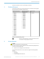
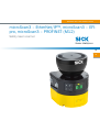
Dieses Dokument gilt für den Sicherheits-Laserscanner microScan3 und den zugehöri‐
g
en Systemstecker mit folgenden Artikelnummern:
Sicherheits-Laserscanner Sicherheits-Laserscanner
ohne S
ystemstecker
Systemstecker
•
1082015
•
1082016
•
1091037
•
1091038
•
1092538
•
1092539
•
1092542
•
1092543
•
1092720
•
1092721
•
1094455
•
1094457
•
1094461
•
1094463
•
1094465
•
1100404
•
1100406
•
1100408
•
1102625
•
1102626
•
1102627
•
1102628
•
1102629
•
1102630
•
1103032
•
1103033
•
1069680
•
1069682
•
1069685
•
1069687
•
1075845
•
1075848
•
1092540
•
1092541
•
1092718
•
1092719
•
1094453
•
1094456
•
1094460
•
1094462
•
1094464
•
1100403
•
1100405
•
1100407
•
2086102
Symbole und Dokumentkonventionen
A, B Verweise auf die Abbildungen am Ende dieses Dokuments sind
mit sc
hwarzem Hintergrund gekennzeichnet.
2 Zu Ihrer Sicherheit
GEFAHR
G
efahr der Unwirksamkeit der Schutzeinrichtung
Der Gefahr bringende Zustand der Maschine wird bei Nichtbeachtung möglicherweise
nicht oder nicht rechtzeitig beendet.
b
Beachten Sie den beiliegenden Sicherheitshinweis.
Der Sicherheits-Laserscanner ist unter anderem für folgende Verwendungen nic
ht
geeignet:
•
Im Freien
•
Unter Wasser
•
In explosionsgefährdeten Bereichen
MONTAGEANLEITUNG
8020210/14BK/2019-07-04 | SICK M O N T A G E A N L E I T U N G | microScan3 – EtherNet/IP™, microScan3 – EFI-pro, microScan3 – PROFINET (M12)
3
Irrtümer und Änderungen vorbehalten

Weitere Informationen zur Arbeit mit der Schutzeinrichtung enthält die Maschinendoku‐
ment
ation oder die Betriebsanleitung der Schutzeinrichtung. Sie finden die EU-Konfor‐
mitätserklärung und die aktuelle Betriebsanleitung der Schutzeinrichtung, indem Sie
auf www.sick.com im Suchfeld die Artikelnummer eingeben (Artikelnummer: siehe
Typenschildeintrag im Feld „Ident. no.“).
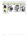
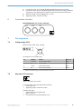
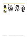
3 Überblick über das Gerät
Überblick:
A
1
Optikhaube
2
Display
3
Tastenfeld
4
USB-Anschluss
5
Status-LEDs
6
Zusätzliche LEDs für EIN-Zustand und AUS-Zustand
7
Netzwerk-LEDs
8
Sicherheits-Laserscanner ohne Systemstecker
9
Systemstecker
ß
Abdeckplatte
Der USB-Anschluss (USB 2.0 Mini-B, Dose) darf nur vorübergehend und nur für die Kon‐
figuration und Diagnose verwendet werden.
4 Position des Systemsteckers ändern
Position des Systemsteckers ändern:
B
Bei A
uslieferung des Sicherheits-Laserscanners ist der Systemstecker unten oder hin‐
ten montiert. Bei Bedarf können Sie die Position des Systemsteckers ändern.
Benötigtes Werkzeug:
•
Sc
hraubenschlüssel Innensechsrund TX20
Vorgehensweise
1. Schrauben des Systemsteckers lösen.
2. Systemstecker vorsichtig vom Sicherheits-Laserscanner abnehmen.
3. Schrauben der Abdeckplatte lösen.
4. Abdeckplatte vom Sicherheits-Laserscanner abnehmen.
5. Systemstecker vorsichtig an der gewünschten Stelle (hinten oder unten) in den
Sicherheits-Laserscanner schieben.
6. Systemstecker mit den unverlierbaren Schrauben anschrauben. Anzugsdrehmo‐
ment: 2,25 Nm … 2,75 Nm.
7. Abdeckplatte am Sicherheits-Laserscanner anschrauben. Anzugsdrehmoment:
2,25 Nm … 2,75 Nm.
5 Sicherheits-Laserscanner direkt montieren
Direktmontage:
C
D
er Sicherheits-Laserscanner hat an der Rückseite 4 M5-Gewindebohrungen. Wenn Sie
die Montagefläche von hinten durchbohren können, können Sie den Sicherheits-Laser‐
scanner mit diesen Gewindebohrungen direkt montieren.
MONTAGEANLEITUNG
4
M O N T A G E A N L E I T U N G | microScan3 – EtherNet/IP™, microScan3 – EFI-pro, microScan3 – PROFINET (M12) 8020210/14BK/2019-07-04 | SICK
Irrtümer und Änderungen vorbehalten

b Zur Dir
ektmontage entweder die rückseitigen 1 oder die seitlichen 2 M5-Gewin‐
debohrungen verwenden.
b
Zur Direktmontage alle 4 rückseitigen oder alle 4 seitlichen M5-Gewindebohrun‐
gen verwenden, damit die im Datenblatt genannten Werte für Schwing- und
Schockfestigkeit erreicht werden.
b
Maximale Einschraubtiefe: 7,5 mm.
b
Anzugsdrehmoment: 4,5 Nm … 5,0 Nm.
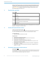
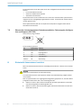
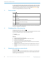
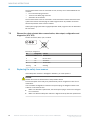
6 Anschlussübersicht
MICSX-BANNZZZZ1 (Artikelnummer: 2086102)
XD1 XF1 XF2
7 Anschlussbelegung
7.1 Spannungsversorgung (XD1)
Stecker, M12, 4-polig, A-codiert.
12
3 4
Anschlussbelegung der Spannungsversorgung
Pin Bezeichnung Funktion Aderfarbe
1)
1 +24 V DC Versorgungsspannung +24 V DC Braun
2 NC Unbeschaltet Weiß
3 0 V DC Versorgungsspannung 0 V DC Blau
4 FE Funktionserde/Abschirmung Schwarz
1)
Gilt für die als Zubehör empfohlenen Anschlussleitungen.
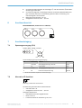
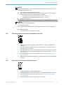
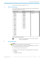
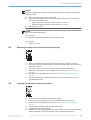
7.2 Alternativer FE-Anschluss
Abbildung 1: Alternativer FE-Anschluss
V
erschraubung des alternativen FE-Anschlusses
•
Schraube: M5 × 12
•
Anzugsdrehmoment: 3,5 Nm … 5,0 Nm
Geeignete Kabelschuhe
•
Gabelkabelschuh oder Ringkabelschuh
•
Breite ≤ 10 mm
•
Lochdurchmesser für Schraube: typ. 5,2 mm
MONTAGEANLEITUNG
8020210/14BK/2019-07-04 | SICK M O N T A G E A N L E I T U N G | microScan3 – EtherNet/IP™, microScan3 – EFI-pro, microScan3 – PROFINET (M12)
5
Irrtümer und Änderungen vorbehalten

Die Funktionserde muss über genau einen der verfügbaren FE-Anschlüsse verbunden
w
erden:
•
Pin am M12-Steckverbinder
•
Gewinde am M12-Steckverbinder
•
Alternativer FE-Anschluss
Die Funktionserde muss induktionsarm und mit einem ausreichenden Querschnitt bei
möglichst kurzer Leitungslänge angeschlossen werden. Funktionserde und Schutzerde
müssen getrennt sein.
Ältere Systemstecker (älter als ca. September 2019) haben möglicherweise keinen
alt
ernativen FE-Anschluss.
7.3 Ethernet für sicherheitsgerichtete Datenkommunikation, Datenausgabe, Konfigura‐
t
ion und Diagnose (XF1, XF2)
Dose, M12, 4-polig, D-codiert.
43
2 1
Anschlussbelegung Ethernet
Pin Bezeichnung Funktion
1 TX+ Sendedaten +
2 RX+ Empfangsdaten +
3 TX– Sendedaten –
4 RX– Empfangsdaten –
Gehäuse SH Abschirmung
8 Sicherheits-Laserscanner tauschen
Wenn der Sicherheits-Laserscanner beschädigt oder defekt ist, müssen Sie ihn austau‐
sc
hen.
GEFAHR
G
efahr der Unwirksamkeit der Schutzeinrichtung
Zu schützende Personen und Körperteile werden bei Nichtbeachtung möglicherweise
nicht erkannt.
Falls im Systemstecker eine ungeeignete Konfiguration gespeichert ist, wird der Gefahr
bringende Zustand nicht oder nicht rechtzeitig beendet.
b
Stellen Sie sicher, dass nach dem Austausch derselbe Systemstecker verwendet
oder die Konfiguration wiederhergestellt wird.
b
Stellen Sie sicher, dass die Ausrichtung des Sicherheits-Laserscanners nach dem
Austausch korrekt ist.
MONTAGEANLEITUNG
6
M O N T A G E A N L E I T U N G | microScan3 – EtherNet/IP™, microScan3 – EFI-pro, microScan3 – PROFINET (M12) 8020210/14BK/2019-07-04 | SICK
Irrtümer und Änderungen vorbehalten

WICHTIG
Die Sc
hutzart IP65 gilt nur, wenn der Sicherheits-Laserscanner verschlossen ist und
der Systemstecker montiert ist.
b
Systemstecker und Abdeckplatte montieren.
b
Jeden M12-Steckverbinder des Sicherheits-Laserscanners mit einem Leitungs‐
steckverbinder oder mit einer Schutzkappe verschließen.
°
Anzugsdrehmoment für Steckverbinder: 0,4 Nm … 0,6 Nm.
°
Anzugsdrehmoment für Schutzkappen: 0,6 Nm … 0,7 Nm.
b
Optikhaube montieren.
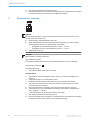
WICHTIG
S
ystemstecker vorsichtig aufstecken.
Keine Gewalt anwenden.
Bei zu großem Kraftaufwand können die Kontakte abbrechen oder sich verbiegen.
Benötigtes Werkzeug:
•
Sc
hraubenschlüssel Innensechsrund TX20
8.1 Sicherheits-Laserscanner ohne Systemstecker tauschen
1. Sicherstellen, dass die Umgebung sauber und frei von Nebel, Feuchtigkeit und
Staub ist.
2. Schrauben des Systemsteckers lösen und Systemstecker vom defekten Sicher‐
heits-Laserscanner entfernen.
3. Befestigungsschrauben lösen und defekten Sicherheits-Laserscanner entfernen.
4. Systemstecker am neuen Sicherheits-Laserscanner montieren, siehe „Systemste‐
cker tauschen“.
5. Neuen Sicherheits-Laserscanner montieren, siehe „Sicherheits-Laserscanner
direkt montieren“.
6. Wirksamkeit der Schutzeinrichtung prüfen. Weitere Informationen: siehe Betriebs‐
anleitung.
8.2 Sicherheits-Laserscanner komplett tauschen
1. Anschlussleitungen vom Systemstecker lösen.
2.
Befestigungsschrauben lösen und defekten Sicherheits-Laserscanner entfernen.
3. Neuen Sicherheits-Laserscanner montieren, siehe „Sicherheits-Laserscanner
direkt montieren“.
4. Anschlussleitungen wieder am Systemstecker anbringen.
MONTAGEANLEITUNG
8020210/14BK/2019-07-04 | SICK M O N T A G E A N L E I T U N G | microScan3 – EtherNet/IP™, microScan3 – EFI-pro, microScan3 – PROFINET (M12)
7
Irrtümer und Änderungen vorbehalten

5. Den Sicherheits-Laserscanner konfigurieren.
6.
Erneute Inbetriebnahme durchführen, insbesondere alle beschriebenen Prüfungen
durchführen. Weitere Informationen: siehe Betriebsanleitung.
9 Systemstecker tauschen
WICHTIG
Die Schutzart IP65 gilt nur, wenn der Sicherheits-Laserscanner verschlossen ist und
der Systemstecker montiert ist.
b
Systemstecker und Abdeckplatte montieren.
b
Jeden M12-Steckverbinder des Sicherheits-Laserscanners mit einem Leitungs‐
steckverbinder oder mit einer Schutzkappe verschließen.
°
Anzugsdrehmoment für Steckverbinder: 0,4 Nm … 0,6 Nm.
°
Anzugsdrehmoment für Schutzkappen: 0,6 Nm … 0,7 Nm.
b
Optikhaube montieren.
WICHTIG
S
ystemstecker vorsichtig aufstecken.
Keine Gewalt anwenden.
Bei zu großem Kraftaufwand können die Kontakte abbrechen oder sich verbiegen.
Systemstecker tauschen: D
Benö
tigtes Werkzeug:
•
Schraubenschlüssel Innensechsrund TX20
Vorgehensweise
1.
Sicherstellen, dass die Umgebung sauber und frei von Nebel, Feuchtigkeit und
Staub ist.
2. Anschlussleitungen vom Systemstecker lösen.
3. Bei Bedarf: Den Sicherheits-Laserscanner an einen sauberen Ort bringen.
4. Schrauben des Systemsteckers lösen und defekten Systemstecker vom Sicher‐
heits-Laserscanner entfernen.
5. Neuen Systemstecker vorsichtig in den Sicherheits-Laserscanner einführen.
6. Systemstecker mit den unverlierbaren Schrauben anschrauben. Anzugsdrehmo‐
ment: 2,25 Nm … 2,75 Nm.
7. Anschlussleitungen wieder am Systemstecker anbringen.
8. Den Sicherheits-Laserscanner konfigurieren.
9. Erneute Inbetriebnahme durchführen, insbesondere alle beschriebenen Prüfungen
durchführen. Weitere Informationen: siehe Betriebsanleitung.
MONTAGEANLEITUNG
8
M O N T A G E A N L E I T U N G | microScan3 – EtherNet/IP™, microScan3 – EFI-pro, microScan3 – PROFINET (M12) 8020210/14BK/2019-07-04 | SICK
Irrtümer und Änderungen vorbehalten

A
B C
1
1 2
2
D
MONTAGEANLEITUNG
8020210/14BK/2019-07-04 | SICK M O N T A G E A N L E I T U N G | microScan3 – EtherNet/IP™, microScan3 – EFI-pro, microScan3 – PROFINET (M12)
9
Irrtümer und Änderungen vorbehalten


All rights reserved. Subject to change without notice.
1 About this document
This document applies to the microScan3 safety laser scanner and the associated sys‐
t
em plug with the following part numbers:
Safety laser scanner Safety laser scanner without
s
ystem plug
System plug
•
1082015
•
1082016
•
1091037
•
1091038
•
1092538
•
1092539
•
1092542
•
1092543
•
1092720
•
1092721
•
1094455
•
1094457
•
1094461
•
1094463
•
1094465
•
1100404
•
1100406
•
1100408
•
1102625
•
1102626
•
1102627
•
1102628
•
1102629
•
1102630
•
1103032
•
1103033
•
1069680
•
1069682
•
1069685
•
1069687
•
1075845
•
1075848
•
1092540
•
1092541
•
1092718
•
1092719
•
1094453
•
1094456
•
1094460
•
1094462
•
1094464
•
1100403
•
1100405
•
1100407
•
2086102
Symbols and document conventions
A, B References to the figures at the end of this document are indi‐
c
ated by a black background.
2 Safety information
DANGER
H
azard due to lack of effectiveness of the protective device
In the case of non-compliance, it is possible that the dangerous state of the machine
may not be stopped or not stopped in a timely manner.
b
Please observe the safety notes provided.
The safety laser scanner is no
t suitable for the following applications, among others:
•
Outdoors
•
Underwater
•
In explosive environments
MOUNTING INSTRUCTIONS
8020210/14BK/2019-07-04 | SICK M O U N T I N G I N S T R U C T I O N S | microScan3 – EtherNet/IP™, microScan3 – EFI-pro, microScan3 – PROFINET (M12)
11
Subject to change without notice

For more information about how to work with the protective device, refer to the machin‐
er
y documentation or the operating instructions for the protective device. You can call
up the EU declaration of conformity and the current operating instructions for the pro‐
tective device by entering the part number in the search field at www.sick.com (part
number: see the type label entry in the “Ident. no.” field).
3 Device overview
Overview:
A
1
Optics cover
2
Display
3
Keypad
4
USB port
5
Status LEDs
6
Additional LEDs for ON state and OFF state
7
Network LEDs
8
Safety laser scanner without system plug
9
System plug
ß
Cover plate
The USB connection (USB 2.0 Mini-B, female connector) may only be used temporarily
and only for configuration and diagnostics.
4 Changing position of the system plug
Changing the position of the system plug:
B
T
he system plug is installed at the bottom or rear when the safety laser scanner is deliv‐
ered. You can change the position of the system plug if needed.
Tool required:
•
T
X20 Torx wrench
Approach
1. Loosen the screws of the system plug.
2. Carefully remove the system plug from the safety laser scanner.
3. Loosen the cover plate screws.
4. Remove the cover plate from the safety laser scanner.
5. Carefully slide the new system plug into the safety laser scanner at the desired
position (bottom or rear).
6. Screw in the system plug using the captive screws. Tightening torque: 2.25 Nm …
2.75 Nm.
7. Install the cover plate on the safety laser scanner. Tightening torque: 2.25 Nm …
2.75 Nm.
5 Mounting the safety laser scanner directly
Direct mounting:
C
T
he safety laser scanner has 4 M5 threaded holes on the back. If you are able to drill
through the mounting surface from the rear, you can mount the safety laser scanner
directly using these threaded holes.
MOUNTING INSTRUCTIONS
12
M O U N T I N G I N S T R U C T I O N S | microScan3 – EtherNet/IP™, microScan3 – EFI-pro, microScan3 – PROFINET (M12) 8020210/14BK/2019-07-04 | SICK
Subject to change without notice

b Use eit
her the rear 1 or the side 2 M5 threaded holes for direct mounting.
b
Use all four rear or all four side M5 threaded holes for direct mounting, so that the
values given in the data sheet for vibration and shock resistance are achieved.
b
Maximum depth of thread engagement: 7.5 mm.
b
Tightening torque: 4.5 Nm to 5.0 Nm.
6 Connection overview
MICSX-BANNZZZZ1 (part number: 2086102)
XD1 XF1 XF2
7 Pin assignment
7.1 Voltage supply (XD1)
Male connector, M12, 4-pin, A-coded.
12
3 4
Pin assignment of the voltage supply
Pin Marking Function Wire color
1)
1 +24 V DC 24 V DC supply voltage Brown
2 NC Not connected White
3 0 V DC 0 V DC supply voltage Blue
4 FE Functional earth/shield Black
1)
Applies to the connecting cables recommended as accessories.
7.2 Alternative FE connection
Figure 1: Alternative FE connection
Scr
ew connection of the alternative FE connection
•
Screw: M5 × 12
•
Tightening torque: 3.5 Nm to 5.0 Nm
Suitable cable lugs
•
Forked cable lug or ring cable lug
•
Width ≤ 10 mm
•
Hole diameter for screw: typically 5.2 mm
MOUNTING INSTRUCTIONS
8020210/14BK/2019-07-04 | SICK M O U N T I N G I N S T R U C T I O N S | microScan3 – EtherNet/IP™, microScan3 – EFI-pro, microScan3 – PROFINET (M12)
13
Subject to change without notice

The functional earth must be connected via one, and only one of the available FE con‐
nec
tions:
•
Pin on the M12 plug connector
•
Thread on the M12 plug connector
•
Alternative FE connection
The functional earth must be connected in a low-inductance manner and with an ade‐
quate cross-section while keeping the cable length as short as possible. Functional
earth and protection earth must be isolated.
Older system plugs (older than roughly September 2019) might not have an alternative
FE c
onnection.
7.3 Ethernet for safety-oriented data communication, data output, configuration and
dia
gnostics (XF1, XF2)
Female connector, M12, 4-pin, D-coded.
43
2 1
Ethernet pin assignment
Pin Designation Function
1 TX+ Send data +
2 RX+ Receive data +
3 TX– Send data -
4 RX– Receive data -
Housing SH Shielding
8 Replacing the safety laser scanner
If the safety laser scanner is damaged or defective, you must replace it.
DANGER
H
azard due to lack of effectiveness of the protective device
Persons and parts of the body to be protected may not be recognized in case of non-
observance.
If an unsuitable configuration is saved in the system plug, the dangerous state is not
ended or is not ended in time.
b
Make sure that after replacement, the same system plug is used or the configura‐
tion is restored.
b
Make sure that the safety laser scanner is aligned correctly after the replacement.
MOUNTING INSTRUCTIONS
14
M O U N T I N G I N S T R U C T I O N S | microScan3 – EtherNet/IP™, microScan3 – EFI-pro, microScan3 – PROFINET (M12) 8020210/14BK/2019-07-04 | SICK
Subject to change without notice

NOTICE
Enc
losure rating IP65 only applies if the safety laser scanner is closed and the system
plug is mounted.
b
Mount the system plug and the cover plate.
b
Close each M12 plug connector on the safety laser scanner using a male cable
connector or a protective cap.
°
Tightening torque for plug connector: 0.4 Nm … 0.6 Nm.
°
Tightening torque for protective caps: 0.6 Nm … 0.7 Nm.
b
Mount the optics cover.
NOTICE
P
lug in the system plug carefully.
Do not force it.
The contacts may break off or bend if too much force is used.
Tool required:
•
T
X20 Torx wrench
8.1 Replacing the safety laser scanner without system plug
1. Make sure that the environment is clean and clear of fog, moisture, and dust.
2. Unscrew screws in the system plug and remove the system plug from the defective
safety laser scanner.
3. Unscrew the fixing screws and remove the defective safety laser scanner.
4. Mount the system plug on the new safety laser scanner, see “Replacing the sys‐
tem plug”.
5. Mount the new safety laser scanner, see “Mounting the safety laser scanner
directly”.
6. Check the effectiveness of the protective device. For more information, see the
operating instructions.
8.2 Completely replacing the safety laser scanner
1. Disconnect the connecting cables the system plug.
2.
Unscrew the fixing screws and remove the defective safety laser scanner.
3. Mount the new safety laser scanner, see “Mounting the safety laser scanner
directly”.
4. Reconnect the connecting cables to the system plug.
5. Configure the safety laser scanner.
6. Perform commissioning again, taking particular care to conduct all of the thorough
checks described. For more information, see the operating instructions.
MOUNTING INSTRUCTIONS
8020210/14BK/2019-07-04 | SICK M O U N T I N G I N S T R U C T I O N S | microScan3 – EtherNet/IP™, microScan3 – EFI-pro, microScan3 – PROFINET (M12)
15
Subject to change without notice

9 Replacing the system plug
NOTICE
Enclosure rating IP65 only applies if the safety laser scanner is closed and the system
plug is mounted.
b
Mount the system plug and the cover plate.
b
Close each M12 plug connector on the safety laser scanner using a male cable
connector or a protective cap.
°
Tightening torque for plug connector: 0.4 Nm … 0.6 Nm.
°
Tightening torque for protective caps: 0.6 Nm … 0.7 Nm.
b
Mount the optics cover.
NOTICE
P
lug in the system plug carefully.
Do not force it.
The contacts may break off or bend if too much force is used.
Replacing the system plug: D
T
ool required:
•
TX20 Torx wrench
Approach
1.
Make sure that the environment is clean and clear of fog, moisture, and dust.
2. Disconnect the connecting cables the system plug.
3. If necessary: move the safety laser scanner to a clean location.
4. Unscrew screws in the defective system plug and remove the system plug from the
safety laser scanner.
5. Carefully insert the new system plug into the safety laser scanner.
6. Screw in the system plug using the captive screws. Tightening torque: 2.25 Nm to
2.75 Nm.
7. Reconnect the connecting cables to the system plug.
8. Configure the safety laser scanner.
9. Perform commissioning again, taking particular care to conduct all of the thorough
checks described. For more information, see the operating instructions.
MOUNTING INSTRUCTIONS
16
M O U N T I N G I N S T R U C T I O N S | microScan3 – EtherNet/IP™, microScan3 – EFI-pro, microScan3 – PROFINET (M12) 8020210/14BK/2019-07-04 | SICK
Subject to change without notice

A
B C
1
1 2
2
D
MOUNTING INSTRUCTIONS
8020210/14BK/2019-07-04 | SICK M O U N T I N G I N S T R U C T I O N S | microScan3 – EtherNet/IP™, microScan3 – EFI-pro, microScan3 – PROFINET (M12)
17
Subject to change without notice

Detailed addresses and further locations at www.sick.com
Australia
Phone +61 (3) 9457 0600
1800 33 48 02 – tollfree
E-Mail [email protected]
Austria
Phone +43 (0) 2236 62288-0
E-Mail [email protected]
Belgium/Luxembourg
Phone +32 (0) 2 466 55 66
E-Mail inf[email protected]
Brazil
Phone +55 11 3215-4900
E-Mail comer[email protected]
Canada
Phone +1 905.771.1444
E-Mail [email protected]
Czech Republic
Phone +420 234 719 500
E-Mail sick@sick.cz
Chile
Phone +56 (2) 2274 7430
E-Mail [email protected]
China
Phone +86 20 2882 3600
E-Mail info.c[email protected]
Denmark
Phone +45 45 82 64 00
E-Mail sick@sick.dk
Finland
Phone +358-9-25 15 800
E-Mail sick@sick.fi
France
Phone +33 1 64 62 35 00
E-Mail inf[email protected]
Germany
Phone +49 (0) 2 11 53 010
E-Mail inf[email protected]
Greece
Phone +30 210 6825100
E-Mail [email protected]
Hong Kong
Phone +852 2153 6300
E-Mail [email protected]
Hungary
Phone +36 1 371 2680
E-Mail ertek[email protected]
India
Phone +91-22-6119 8900
E-Mail info@sick-india.com
Israel
Phone +972 97110 11
E-Mail inf[email protected]
Italy
Phone +39 02 27 43 41
E-Mail inf[email protected]
Japan
Phone +81 3 5309 2112
E-Mail [email protected]
Malaysia
Phone +603-8080 7425
E-Mail enquiry.my@sick.com
Mexico
Phone +52 (472) 748 9451
E-Mail [email protected]
Netherlands
Phone +31 (0) 30 229 25 44
E-Mail inf[email protected]
New Zealand
Phone +64 9 415 0459
0800 222 278 – tollfree
E-Mail [email protected]
Norway
Phone +47 67 81 50 00
E-Mail sick@sick.no
Poland
Phone +48 22 539 41 00
E-Mail inf[email protected]
Romania
Phone +40 356-17 11 20
E-Mail [email protected]
Russia
Phone +7 495 283 09 90
E-Mail inf[email protected]
Singapore
Phone +65 6744 3732
E-Mail [email protected]
Slovakia
Phone +421 482 901 201
E-Mail mail@sick-sk.sk
Slovenia
Phone +386 591 78849
E-Mail [email protected]
South Africa
Phone +27 10 060 0550
E-Mail info@sickautomation.co.za
South Korea
Phone +82 2 786 6321/4
E-Mail infokor[email protected]
Spain
Phone +34 93 480 31 00
E-Mail inf[email protected]
Sweden
Phone +46 10 110 10 00
E-Mail inf[email protected]
Switzerland
Phone +41 41 619 29 39
E-Mail [email protected]
Taiwan
Phone +886-2-2375-6288
E-Mail [email protected]
Thailand
Phone +66 2 645 0009
E-Mail mar[email protected]
Turkey
Phone +90 (216) 528 50 00
E-Mail inf[email protected]
United Arab Emirates
Phone +971 (0) 4 88 65 878
E-Mail [email protected]
United Kingdom
Phone +44 (0)17278 31121
E-Mail inf[email protected]
USA
Phone +1 800.325.7425
E-Mail inf[email protected]
Vietnam
Phone +65 6744 3732
E-Mail [email protected]
SICK AG | Waldkirch | Germany | www.sick.com
8020210/14BK/2019-07-04/de, en
-
 1
1
-
 2
2
-
 3
3
-
 4
4
-
 5
5
-
 6
6
-
 7
7
-
 8
8
-
 9
9
-
 10
10
-
 11
11
-
 12
12
-
 13
13
-
 14
14
-
 15
15
-
 16
16
-
 17
17
-
 18
18


SICK microScan3 – EtherNet/IP™, microScan3 – EFIpro, microScan3 – PROFINET (M12) Mounting instructions
- Typ
- Mounting instructions
- Dieses Handbuch eignet sich auch für
in anderen Sprachen
Verwandte Artikel
-
SICK microScan3 – EtherNet/IP™, microScan3 – EFIpro, microScan3 – PROFINET (M12) Mounting instructions
-
-
-
-
-
-
-
-
-