
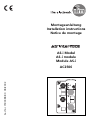
Montageanleitung
Installation instructions
Notice de montage
AS-i Modul
AS-i module
Module AS-i
AC2506
Sachnr. 7390388/00 08/2002

Bestimmungsgemäße Verwendung
• AS-i-Profil S-0.1.E
• maximale Anzahl von Modulen pro Master: 31
• AS-Interface Version 2.1
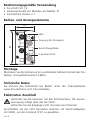
Bedien- und Anzeigeelemente
Montage
Montieren Sie das Modul auf ein verdrahtetes Modul-Unterteil des AS-i
Netzes, Anzugsdrehmoment 0,8Nm.
Technische Daten
Sie können das Datenblatt bei Bedarf unter der Internetadresse
www.ifm-electronic.com herunterladen.
Elektrischer Anschluß
Verbinden Sie die Sensoren mit den M12-Buchsen. Die Sensor-
versorgung erfolgt über das AS-i Netz.
Verbinden Sie die Eingänge nicht mit externem Potential.
Verschließen Sie die nicht benutzten Buchsen mit Verschlußkappen
(AC3004), um die Schutzart IP 67 zu gewähren.
SEITE 2
83
45
LEDs
2 Buchsen M12
Beschriftungsfelder
Fixierung für IR-Adapter

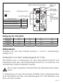
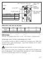
Belegung der Datenbits
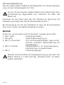
Adressieren
Vergeben Sie eine freie Adresse zwischen 1 und 31, Auslieferungs-
adresse ist 0.
Adressieren mit dem Adressiergerät AC1144
Das Modul kann in Verbindung mit dem FK-Unterteil AC5010 (mit
Adressierbuchse) über das Adressierkabel (E70213) in montiertem und
verdrahtetem Zustand adressiert werden.
Nur im spannungslosen Zustand über die Adressierbuchse adres-
sieren.
In Verbindung mit dem FK-Unterteil AC5000 (ohne Adressierbuchse)
muß das Modul erst über das Adressiergerät AC1144 adressiert und
dann montiert werden.
SEITE 3
4x LED1 gelb
LED2 rot
FAULT
LED grün
PWR
Spannungs-
versorgung
o.k
2 Buchsen M12
Eingänge
1
34
2
5
M12-Buchse Pin
1
Sensorversorgung L- 3
5
Sensorversorgung L+
Fixierung
IR-Adapter
LED3 Infrarot-Empfänger
Datenbit D0 D1 D2 D3
Eingang 1 2 3 4
Buchse I-1/2 I-1/2 I-3/4 I-3/4
PIN 4 2 4 2

Infrarot-Adressierung
Das AS-i Modul bietet zusätzlich die Möglichkeit zur Infrarot-Adressie-
rung mit dem Adressiergerät AC1144.
Die AS-i Kommunikation (gelbes Kabel) muß während der Infra-
rot-Adressierung abgeschaltet sein. Klemmen Sie dafür den
Master ab.
Versorgen Sie die Slaves über das AS-i Netzteil mit Spannung. Die
Adressierung erfolgt über das IR-Adressierkabel E70211.
Bei Verwendung von ifm AS-i Netzteilen SL kann die Kommunikation
über einen Stecker am Netzteil deaktiviert werden.
Betrieb
Prüfen Sie, ob das Gerät sicher funktioniert. Anzeige durch LEDs:
•LED 1 gelb: Eingang geschaltet
•LED grün: Spannungsversorgung o.k.
•LED 2 rot leuchtet: AS-i Kommunikationsfehler, Slave nimmt
nicht am „normalen“ Datenverkehr teil, z. B.
Slaveadresse 0
•LED 2 rot blinkt: Peripheriefehler, z. B. Sensorversorgung
überlastet bzw. kurzgeschlossen
•LED 3: Infrarot-Empfänger
Überlast und Kurzschluß der Eingangsversorgung wird dem AS-i
Master (Version 2.1) über das Flag „Periphery Fault“ im Status-
register signalisiert.
SEITE 4

Function and features
•AS-i profile: S-0.1.E
•maximum number of modules per master: 31
•AS-interface version 2.1
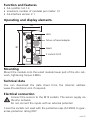
Operating and display elements
Mounting
Mount the module onto the wired module lower part of the AS-i net-
work, tightening torque 0.8Nm.
Technical data
You can download the data sheet from the Internet address
www.ifm-electronic.com if required.
Electrical connection
Connect the sensors to the M12 sockets. The sensor supply via
the AS-i network.
Do not connect the inputs with an external potential.
Cover the sockets not used with the protective caps (AC3004) to guar-
antee protection rating IP67.
PAGE 5
83
45
LEDs
2 sockets M12
labels
fixture infrared adapter

Data bits
Addressing
Assign a free address between 1 and 31. At the factory the address is
set to 0.
Addressing with the addressing unit AC1144
If the mounted and wired module is used with the FC lower part
AC5010 (with addressing socket), it can be addressed via the address-
ing cable (E70213).
Do not remove the addressing plug while live.
If it is used with the FC lower part AC5000 (without addressing sock-
et) the module must first be addressed via the addressing unit AC1144
and then mounted onto the lower part.
PAGE 6
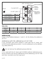
4x LED1 yellow
LED2 red FAULT
LED green
PWR sensor
supply o.k
2 sockets M12
inputs
1
34
2
5
socket M12 pin
1
sensor supply L- 3
5
sensor supply L+
fixture
infrared
adapter
LED3 infrared reciever
Data bit D0 D1 D2 D3
Input 1 2 3 4
Socket I-1/2 I-1/2 I-3/4 I-3/4
Pin 4 2 4 2

Infrared addressing
The AS-i module also offers the option of infrared addressing with the
addressing unit AC1144.
The AS-i communication (yellow cable) must be switched off
during the infrared addressing. To do so, disconnect the master.
Supply the slaves with voltage via the AS-i power supply. Addressing is
carried out via the IR addressing cable E70211.
When the ifm AS-i power supplies SL are used the communication can
be deactivated via a plug on the power supply.
Operation
Check the safe functioning of the unit. Display by LEDs:
•LED 1 yellow: input switched
•LED green: voltage supply o.k.
•LED 2 red is lit: AS-i communication error, slave does not
participate in the “normal” data exchange,
e. g. slave address 0
•LED 2 red flashing: peripheral fault, e.g. overload or short cir-
cuit of the sensor supply
•LED 3: infrared reciever
Overload and short circuit of the input supply are signalled to the
AS-i master (version 2.1) via the "peripheral fault" flag in the sta-
tus register.
PAGE 7

Fonctionnement et caractéristiques
•Profil AS-i S-0.1.E
•nombre maximal de modules par maître: 31
•version AS-interface 2.1
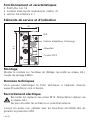
Eléments de service et d’indication
Montage
Monter le module sur l'embase de câblage rac-cordé au réseau AS-i,
couple de serrage 0,8Nm.
Données techniques
Vous pouvez télécharger la fiche technique à l'adresse internet
www.ifm-electronic.com si besoin.
Raccordement électrique
Raccorder les capteurs aux prises M12. Alimentation capteur via
le réseau AS-i.
Ne pas raccorder les entrées à un potentiel externe.
Couvrir les prises non utilisées avec les bouchons (AC3004) afin de
garantir la protection IP67.
PAGE 8
83
45
LED
2 prises M12
étiquettes
fixation adaptateur infrarouge

Affectation des bits de données
Adressage
Affecter une adresse libre entre 1 et 31. A la livraison, l'adresse est 0.
Adressage avec l'unité d'adressage AC1144
Si le module monté et câblé est utilisé avec l'embase pour câble plat
AC5010 (avec prise d'adressage), il peut être adressé via le cordon
d'adressage (E70213).
Ne pas retirer la prise d'adressage sous tension.
Si le module est utilisé avec l'embase pour câble plat FK AC5000 (sans
prise d'adressage) il doit d'abord être adressé via l'unité d'adressage
AC1144 et ensuite être monté sur l'embase.
PAGE 9
4x LED1 jaunes
LED2 rouge
FAULT
LED verte PWR
alimentation
capteur o.k
2 prises M12
entrées
1
34
2
5
prise M12 broche
1
alimentation capteur L- 3
5
alimentation capteur L+
fixation
adaptateur
infrarouge
LED3 récepteur infrarouge
Bit de données D0 D1 D2 D3
Entrée 1 2 3 4
Prise I-1/2 I-1/2 I-3/4 I-3/4
Broche 4 2 4 2

Adressage infrarouge
Le module AS-i offre également l'option d'adressage infrarouge par
l’unité d'adressage AC1144.
La communication AS-i (câble jaune) doit être désactivée pen-
dant l'adressage infrarouge. Pour ce faire, débrancher le maître.
Alimenter les esclaves en tension avec le bloc d'alimentation AS-i.
L'adressage s'effectue via le cordon d'adressage infrarouge E70211.
Lorsque des blocs d'alimentation ifm AS-i SL sont utilisés, la communi-
cation peut être désactivée par un connecteur sur le bloc d'alimentation.
Fonctionnement
Vérifier le bon fonctionnement du module. Affichage par LED:
•LED jaune: entrées commutées
•LED verte: alimentation o.k.
•LED 2 rouge allumée: erreur de communication AS-i, esclave ne
participe pas à l'échange "normal" des
données, p. ex. adresse d'esclave 0
•LED 2 rouge clignote: défaut périphérique, p.ex. surcharge ou
court-circuit de l'alimentation des capteurs
•LED 3: récepteur infrarouge
La surcharge et le court-circuit de l'alimentation des entrées sont
signalisés au maître AS-i (version 2.1) via le bit interne "défaut
périphérique" dans le registre d'états.
PAGE 10
-
 1
1
-
 2
2
-
 3
3
-
 4
4
-
 5
5
-
 6
6
-
 7
7
-
 8
8
-
 9
9
-
 10
10


in anderen Sprachen
- English: IFM AC2506 Installation guide
- français: IFM AC2506 Guide d'installation
Verwandte Artikel
Andere Dokumente
-
SICK UE3212 AS-interface Safety at Work Safe Bus node Bedienungsanleitung
-
-
Pepperl+Fuchs VBA-8E8A8A-KE4-ZEL/E2L/SEL Bedienungsanleitung
-
Gossen MetraWatt METRAHit ASi V3.0 Bedienungsanleitung
-
-
CAME PXC2 Installationsanleitung