Josef Kihlberg JK20-680 Benutzerhandbuch
- Kategorie
- Nagelpistole
- Typ
- Benutzerhandbuch

05.20
JK20-680
Pneumatic stapler
Pneumatiskt klammerverktyg
Pneumatisches Klammergerät
Agrafeuse pneumatique
From serie no 141334
Från serienummer 141334
Ab Serie-Nr. 141334
A partir du no de série 141334
ENGLISH 3
SVENSKA 12
DEUTSCH 22
FRANÇAIS 32
Before using the tool,
read the operating in-
structions carefully.
Läs igenom bruks-
anvisningen noga innan
du använder klammer-
verktyget.
Vor dem Gebrauch des
Gerätes die Betriebs-
anleitung aufmerksam
lesen.
Avant l’utilisation de
l’appareil, consultez
soigneusement le
mode d’emploi.
OPERATING INSTRUCTIONS Translation of original manual
BRUKSANVISNING Original bruksanvisning
BETRIEBSANLEITUNG Übersetzung der Originalbetriebsanleitung
MODE D‘EMPLOI Traduction du mode d’emploi original

205.20
Josef Kihlberg JK20-680
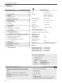
1 TECHNICAL DATA
TABLE OF CONTENTS
Weight 1.0 kg (2.2 lbs)
Dimensions Length 230 mm (9,1“)
Width 43 mm (1,7“)
Height 150 mm (5,9“)
Magazine capacity 143 staples
Staple leg length 6–14 mm (1/4“–9/16“)
Nose length 14 mm (0.5 in.)
Recommended
working air pressure 5–6 bar (72–87 psi)
Max. air pressure 7 bar (100 psi)
Air consumption
per driving operation at
6 bar operating pressure 0.2 litres
Noise characteristic levels
according to: EN 12549
A-weighted single-event
emission sound pressure
level at work station 85 dB
A-weighted sound
energy level 91 dB
Vibration level: Vibration below the limit of
declaration according to
EN 792-13 measured
according to ISO 8662-11.
FASTENERS
Staple JK680-06 (1/4“) Art.No 400283
Staple JK680-08 (5/16“) Art.No 400285
Staple JK680-10 (3/8“) Art.No 400288
Staple JK680-12 (1/2“) Art.No 400292
Staple JK680-14 (9/16“) Art.No 400294
Page
1 Technical data 2
2 General information 3
2.1 Information on environmental protection 3
3 Safety instructions 4
4 Description 5
4.1 Design 5
4.2 Function 5
5 Initial operation 6
5.1 Installation 6
5.2 Compressed-air connection / Lubrication 6
6 Operating instructions 7
6.1 Loading the stapler 7
6.2 Operating the stapler 7
7 Preventive and corrective maintenance 8
7.1 Cleaning the stapler 8
7.2 Removing jammed staples 8
7.3 Replace feed spring or pusher 9
7.4 Replace driver blade 9
8 Trouble shooting 10
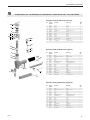
9 Spare parts kit 41
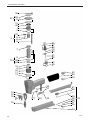
10 Exploded drawing 42
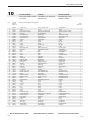
Parts list with recommended wear parts 44
DECLARATION OF CONFORMITY
We take sole responsibility for declaring that the
stapler JK20-680, to which this declaration refers, is
in full compliance with the current require-
ments of the guidelines laid down by the council
on 17th May 2006 (2006/42/EC) “Machine
Guidelines“.
According to norm:
ISO 12100:2010; EN 792-13+A1:2008
SE-544 50 HJO, 05.05.2020
Plant Manager:
Thor-Björn Elmers
Agent for the publication of technical documentation:
Josef Kihlberg AB, Industrigatan 37B, SE-544 50 HJO
SE JOSEF KIHLBERG AB
Industrigatan 37B
SE- 544 50 Hjo
Telephone: +46 503 328 00
Fax: +46 503 328 01
Internet: www.kihlberg.com

05.20 3
Josef Kihlberg JK20-680
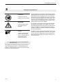
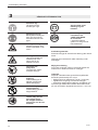
CAUTION!
Used where there is
danger to life and health.
WARNING!
Used for danger which
can cause material
damage.
NOTE!
Used for general infor-
mation and information
which if not followed can
cause faults in the
operating sequence.
2 GENERAL INFORMATION
These operating instructions are intended to simplify
familiarisation with the stapler and the possibilities of
application for the intended purpose. The operating
instructions contain important information concerning
the safe, proper and efcient use of the stapler. Ob-
servation of the information will help to avoid danger,
reduce repairs and stoppages and increase the reli-
ability and service life of the stapler.
The operating instructions must always be available
at the place of operation of the stapler. They must
be read and observed by all persons concerned with
work on the stapler. This work specically includes
operation, relling of operating material, fault elimina-
tion and maintenance.
In addition to the operating instructions and the regu-
lations for accident prevention effective in the country
of use and place of application, the recognised tech-
nical regulations for safety and proper working must
also be observed.
2.1 INFORMATION ON ENVIRONMENTAL
PROTECTION
This stapler is manufactured without any physical or
chemical substances which could be dangerous to
health. For disposal of all the parts, the governmental
instructions must be observed.

405.20
Josef Kihlberg JK20-680
Use for the intended purpose
The stapler is intended for stapling fabric to wood,
board or cardboard to wood.
This stapler was designed and manufactured for safe
handling during the stapling operation.
Possible misuse
Do not re any staples into the air or use the stapler
with any other materials than mentioned above.
Servicing
The following maintenance work must be carried out
at regular intervals, varying with working conditions
and workload:
– daily check of compressed air pressure (5–6 bar).
– clean the stapler regularly.
– check the condition of the stapler at regular inter-
vals for defects or worn parts. Never use a stapler
that has defective or worn parts (for servicing tasks
refer also to chapter 7.1 until 7.4).
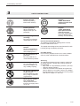
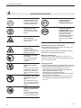
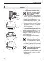
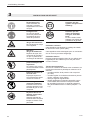
3 SAFETY INSTRUCTIONS
Inform yourself!
Read the operating
instructions carefully.
Protect yourself!
When operating the
stapler, wear eye, ear
protection.
Warning: Danger of
crushing!
Do not put your ngers
underneath the nozzle.
Warning:
Hazard!
Lay the compressed air
hose so that there is no
risk of tripping over it.
Do not exceed the air
pressure!
Do not exceed the re-
commended air pressure.
Use safety coupling!
For connecting the air
hose to the stapler, use
only a safety coupling.
Do not use a bottled air
or gas source!
Do not operate this stap-
ler by using a bottled air
or gas source.
Never leave a loaded
tool unattended!
Always disconnect the
tool from air supply when
not in use.
PD[
EDU
0
2
4
6810
12
14
16
.,+/%(5*
2ULJLQDO
KIHLBERG
Original
Original
JOSEF KIHLBERG
staples must be used
exclusively!
Original
JOSEF KIHLBERG
spare parts must be
used exclusively!
Not using original spare
parts will dissolve the
warranty and the liability.

05.20 5
Josef Kihlberg JK20-680
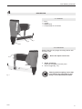
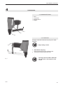
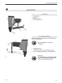
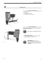
4 DESCRIPTION
4.2 FUNCTION
Stapler JK20 has only single shot ring without with-
out safety yoke.
Never re staples into the air!
1. Single shot ring:
Press the tool against the work piece.
2. Pull the trigger (g. 1/2).
4.1 DESIGN
1 Door
2 Trigger
3 Magazine lid
4 Compressed air connection
Fig. 1
Warning: before stapling ensure that
your hand or any other part of your
body is not underneath the nozzle.
1
23
4

605.20
Josef Kihlberg JK20-680
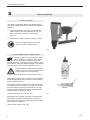
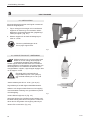
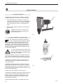
5 INITIAL OPERATION
5.1 INSTALLATION
The stapler is delivered without the compressed air
connection nipple assembled. Assemble the nipple as
following:
1. Take the stapler out of the box. Check that the
nipple is the correct brand and ts your air sys-
tem. Put sealing compound on the thread.
(Fig. 2/1).
2. Assemble the nipple. Tightening torque 7.5 Nm.
Lay the compressed air hose so that
there is no risk of tripping over it.
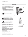
5.2 AIR CONNECTION / LUBRICATION
Properly prepared compressed air is essen-
tial for trouble free operation of the stapler.
This can only be ensured by a reliably functioning
maintenance unit, consisting of water separator, pres-
sure reducing valve with pressure gauge. The internal
diameter of the pipe should be at least 10 mm (3/8“).
Never exceed the maximum permitted air
pressure of 7 bar (100 psi). The maximum
supply pressure is 7 bar (100 psi).
A low air pressure will give low maintenance costs!
The stapler and the hose must have a coupling which
automatically bleeds all air pressure from the stapler
when it is disconnected.
The stapler needs a small amount of lubricating oil in
the nipple each day or approx. 10 drops once a week
to ensure safe functioning and endurance. For high
frequency stapling we recommend oil mist lubricator.
Please contact our agent for advice.
733007 Lubrication oil 0.2 dl. (Fig.3/1)
Sliding parts are greased, with Dow Corning grease
MS 4 Silicon Compound, at the factory. We recom-
mend use of this grease on moving parts if they have
been cleaned or replaced.
184943 Tube of MS 4. (Fig. 3/2)
Fig. 2
1
733007
184943
Fig. 3
1
2

05.20 7
Josef Kihlberg JK20-680
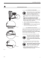
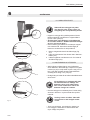
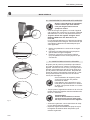
6 OPERATING INSTUCTIONS
6.1 LOADING THE MAGAZINE
– Connect the tool to the compressed air line before
loading staples. The max. allowed air pressure is 7
bar.
–Always use Josef Kihlberg original staples
JK680 with leg length 06 (1/4“ ) to 14 mm
(9/16“). The correct type of staple is marked on the
right side of the magazine. Ensure you use the right
length of staples for your application.
1. Pull the magazine lid all the way out (Fig. 4/1)
2. Place the staple strip (4/2) into the staple rail from
the left hand side.
3. Place the staple strip into the magazine and push
the lid (4/3) forward again until it clicks in.
Be sure that the tool is not pointing at
yourself or anyone else when connec-
ting it to the compressed air line.
Warning: before stapling, ensure that
your hand or any other part of your
body is not underneath the nozzle.
6.2 OPERATING THE STAPLER
Adjust the air pressure to the lowest one that will drive
the staples to the desired depth. Start at approx. 5.0
bar (72 psi) and raise this by 0.5 bar (7 psi) increase
until the correct operating pressure for the job in hand
is found. Never exceed 7 bar (100 psi).
A low air pressure will give low maintenance costs!
– Place the tool rmly on the work surface. Never
drive staples in extremely hard or brittle material.
– Push the trigger as described in chapter 4.2
– Move the toll sideways until you have nished the
stapling and then release the trigger.
Always place yourself in a rmly balan-
ced position when using or handling the
tool. Do not drive staples at too steep
an angle or too close to the edge of the
work: the fastener might y free and hurt
someone.
Fig. 4
1
2
3

805.20
Josef Kihlberg JK20-680
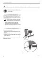
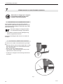
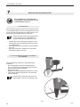
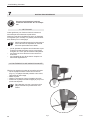
7 PREVENTIVE AND CORRECTIVE MAINTENANCE
Before all maintenance tasks on the
stapler always rst disconnect it from
the air supply.
To remove a jammed staple.
– Pry the door open with a screw driver (g.5/1). It
is three notches in the door to simplied the disas-
semble.
– Remove the door..
– Clean the canal for defective staples.
– Insert the door into the rear nozzle plate and push
until it clicks shut.
Note! The three notches at the door must be as-
sembled to the front.
7.2 REMOVING JAMMED STAPLES
Fig. 5
7.1 CLEANING THE STAPLER
This stapler does not require special servicing. It only
needs regular cleaning with a non-aggressive (non-
corrosive) cleaner agent. Do not remove any parts for
cleaning purposes!
Check the proper functioning of all safety
devices daily. Make especially sure that:
– the trigger works smoothly, the door stays in place
and the magazine lid does not open itself.
– all screws and nuts are securely tightened.
– the stapler is regularly lubricated (refer to chapter
5.2).
1

05.20 9
Josef Kihlberg JK20-680
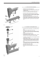
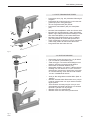
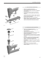
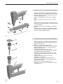
7.3 REPLACE FEED SPRING
7.4 CHANGE THE DRIVER BLADE
– Remove the four screws (Fig. 7/1) holding the top
cap.
– Remove the cylinder liner cover (7/2).
– Turn the tool (7/5) upside down and knock it care-
fully against a piece of wood to loosen the driving
parts.
– Remove the driving parts (7/4).
– Disassemble the piston cpl (7/3).
– Hold the piston and turn the driver blade a 1/4 turn.
Remove the pin and replace the driver blade.
– Assemble in opposite way. Do not forget to turn the
driver blade a 1/4 turn.
– Grease (Part No 184943) at all o-rings and sliding
surfaces. Assemble the driving parts as indicated
in the picture (7/4) and enter the piston cpl. (7/3)
into the driving parts and push it to its lower posi-
tion.
– Insert the driver into the nozzle and push it down.
Check that the piston and the driver move freely in
the cylinder and in the nozzle.
– Mount the cylinder liner cover.
– Mount the top cap and tighten the four screws
(7/1).
– Remove the rear screw (Fig. 6/2).
– Remove the two front screws (6/1) and remove the
magazine (6/3).
– Remove the magazine lid (6/4) towards the front.
– Remove the pusher (6/6) and its spring (6/7).
– Mount the pusher spring under the front roller.
– First mount the pusher; tension the pusher spring a
little, carefully release the pusher and then attach
the spring to the rear hook.
– Mount the lid (6/4) from the front; push the lock
plunger (6/5) in as indicated to allow the lid to pass.
– Put the three magazine screws in place and push
the magazine down. Tighten the two front screws
rst.
Fig. 6
1 2
4 5
3
7
6
Fig. 7
1
2
3
4
5

10 05.20
Josef Kihlberg JK20-680
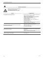
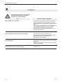
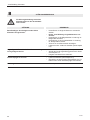
8 TROUBLE SHOOTING
FAULT
No staples when ring the tool.
Inadequate power. The staples do not penetrate
the material sufciently.
Noise level is too high
Jammed staple in the nozzle
ELIMINATION
– Check that the right type of staples is being used
and moves easily inside the rail.
–Always use Josef Kihlberg original staples.
–Check for jammed staples.
– Check the feeder spring for defects. If
necessary replace.
– Check if the staple pusher is not defective. If
necessary replace.
– Clean the staple track.
– Air pressure too low. Secure that working pressure
is as recommend, see chapter 6.2
– Adjust the air pressure as chapter 6.2
– Has the tool been used without oil? Provide lubri-
cation, see chapter 5.2.
– Fit a longer driver blade.
– Check if the air pressure is correct. Adjust as per
chapter 6.2.
– Ensure that the work piece is rmly held in place.
Vibration causes high sound levels.
– Open the door and remove the defective staple,
see chapter 7.2.
Before all trouble shooting tasks on
the stapler it must rst be
disconnected from the air supply.

05.20 11
Josef Kihlberg JK20-680

12 05.20
Josef Kihlberg JK20-680
1 TEKNISKA DATA
INNEHÅLL
Vikt 1,0 kg (2,2 lbs)
Dimension Längd 230 mm (9,1“)
Bredd 43 mm (1,7“)
Höjd 150 mm (5,9“)
Magasinskapacitet 143 klammer
Klammerlängd 6–14 mm (1/4“–9/16“)
Noslängd 14 mm (0,5 in.)
Max. tryck 7 bar (100 psi)
Rekommenderat
arbetstryck 5–6 bar (72–87 psi)
Luftförbrukning per slag vid
6 bar ( 80 psi) arbetstryck. 0,2 liter
Karakteristisk bullernivå enligt: EN 12549
Deklarerad A-vägd
ljudtrycksnivå vid
operatörsplatsen för
enstaka förlopp 85 dB
Deklarerad A-vägd
ljudenerginivå 91 dB
Vibrationsnivå: Vibrationsnivån är under dekla-
rationsgräns enligt EN 292-2 uppmätt enl. ISO 8662-11.
Klammer
Klammer JK680-06 (1/4“) Art. nr 400283
Klammer JK680-08 (5/16“) Art. nr 400285
Klammer JK680-10 (3/8“) Art. nr 400288
Klammer JK680-12 (1/2“) Art. nr 400292
Klammer JK680-14 (9/16“) Art. nr 400294
Page
1 Tekniska data 12
2 Allmänt 13
2.1 Miljöinformation 13
3 Säkerhetsföreskrifter 14
4 Beskrivning 15
4.1 Sammansättning 15
4.2 Funktion 15
5 Idrifttagande 16
5.1 Installation 16
5.2 Anslut tryckluft / smörjning 16
6 Användning 17
6.1 Ladda klammermagasin 17
6.2 Använda klammerverktyget 17
7 Förebyggande och avhjälpande underhåll 18
7.1 Rengöring av klammerverktyget 18
7.2 Avlägsna kilad klammer 18
7.3 Byta frammatarfjäder eller frammatare 19
7.4 Utbyte av drivare 19
8 Felsökning 20
9 Reservdelar som delar 41
10 Sprängskiss 42
Reservdelslista 44
DEKLARATION OM ÖVERENSSTÄMMELSE
Försäkrar härmed att klammerverktyg JK20-680,
är tillverkad enligt följande harmoniserande stan-
darder:
SS-EN ISO 12100:2010 och SS-EN 792-13 +
A1:2008
samt följer bestämmelserna enligt rådets direktiv:
2006/42/EG
SE-544 50 HJO, 05.05.2020
Plant Manager:
Thor-Björn Elmers
Behörig att ställa samman den tekniska dokumentationen:
Josef Kihlberg AB, Industrigatan 37B, SE-544 50 HJO
SE JOSEF KIHLBERG AB
Industrigatan 37B,
SE-544 50 Hjo
Telefone: +46 503 328 00
Fax: +46 503 328 01
Internet: www.kihlberg.com
SVENSKA

05.20 13
Josef Kihlberg JK20-680
FÖRBUD!
Symbolen används vid
fara för liv och lem.
VARNING!
Symbolen används vid
risk för materiella skador.
OBSERVERA!
Symbolen används för
allmänna instruktioner
samt för instruktioner
som måste följas för att
undvika störningar.
2 ALLMÄNT
Denna manual är framtagen för att förenkla kännedom
om klammerverktyget och dess handhavande och
applikationer. Manualen innehåller viktig information
angående säkerhet, korrekt och effektiv användn-
ing. Genom att iakttaga denna information hjälper det
till att förhindra olyckor och reducera reparationer
och driftstörningar och förlänga livslängden på klam-
merverktyget.
Manualen skall alltid hållas tillgänglig i arbetsområdet
för verktyget. Den skall läsas och förstås av all per-
sonal som använder verktyget.
Som tillägg till manualen skall bestämmelse för före-
byggande olycksfallsrisker följas för det land där
produkten används. Det skall också iakttagas tekniska
förordningar angående säker och riktig användning.
2.1 MILJÖINFORMATION
Detta klammerverktyg är tillverkat utan några fysiska
eller kemiska substanser vilka kan vara farliga för
hälsan. För avfallshantering av samtliga delar skall
regeringens lagar och förordningar följas.

14 05.20
Josef Kihlberg JK20-680
Användningsområde
Klammerverktyget är avsett för att häfta tyg eller board
till trä.
Verktyget är konstruerat för säker hantering under
klamringen.
Möjlig felanvänding
Avfyra inte verktyget i luften och använd endast i de
material som rekommenderas för verktyget.
Underhåll
Följande underhåll måste genomföras regelbundet
beroende på arbetsmiljö och volym:
– daglig kontroll av arbetstryck 5–6 bar ( 72-87 psi).
– regelbunden rengöring av klammerverktyget.
– kontrollera regelbundet konditionen på häftaren och
se till att inga defekta eller utslitna delar förekommer.
(för mer information angående service se 7.1 and 7.2).
Informera dig!
Läs igenom bruks-
anvisningen noga.
Skyddsutrustning!
Bär skyddsutrustning för
ögon och öron när du
använder klammerverk-
tyget.
Varning: Akta ngrarna!
Stoppa inte ngrar eller
andra kroppsdelar under
nosen.
Varning: Snubbelrisk!
Lägg tryckluftsslangen
så att det inte nns
någon risk för att
snubbla över den.
Överskrid inte
lufttrycket!
Överskrid inte rekom-
menderat lufttryck.
Använd säkerhets-
koppling!
Anslut luftslangen till
häftaren endast med
säkerhetskoppling.
Använd aldrig gas från
högtryckstuber!
Använd aldrig gas från
högtryckstuber.
Lämna aldrig ett lad-
dat verktyg obeva-
kat. Koppla altid bort
luftslangen när det inte
används.
3 SÄKERHETSFÖRESKRIFTER
PD[
EDU
0
2
4
6810
12
14
16
.,+/%(5*
2ULJLQDO
KIHLBERG
Original
Använd alltid Josef
Kihlberg original
klammer.
Endast original-
reservdelar från
JOSEF KIHLBERG
får användas!
I annat fall upphävs
garanti och övrigt ansvar
från tillverkaren!

05.20 15
Josef Kihlberg JK20-680
4 BESKRIVNING
4.1 SAMMANSÄTTNING
1 Dörr
2 Avtryckare
3 Magasinslock
4 Nippel
Varning! innan du häftar, säkerställ
att ingen del av din kropp är under
nosen.
4.2 FUNKTION
Verktyget JK20-680 enkelskott avfyrning utan säker-
hetsbygel.
Avfyra aldrig i luften!
1. Enkelskotts-avfyrning:
Placera verktyget först mot arbetsstycket.
2. Trycksedan på avtryckaren (g.1/2).
Fig. 1
1
2
3
4

16 05.20
Josef Kihlberg JK20-680
5 IDRIFTTAGANDE
5.1 INSTALLATION
Klammerverktyget levereras med nippeln omonterad.
Monteras enligt följande:
1. Tag ur verktyget ur kartongen och kontrollera att
nippeln är av samma typ som används i luftins-
tallationen. Applicera gängtejp eller gängtätnings
vätska på nippeln. (Fig. 2/1).
2. Montera nippeln och använd ett åtdragningmo-
ment av 7,5 Nm.
5.2 ANSLUT TRYCKLUFT / SMÖRJNING
Placera tryckluftsslangen så att
den ej utgör något hinder.
Fig. 2
1
733007
184943
Fig. 3
1
2
Häftaren behöver ren och torr tryckluft med
tillsats av en liten mängt dimsmörjolja för
en långsiktig problemfri drift. Detta kan
enklast uppnås med en luftberedare som inkluderar
vattenavskiljare och luftregulator med manometer och
dimsmörjarenhet. Som alternativ till detta kan dims-
mörjolja tillföras i nippeln, några droppar dagligen eller
ca 10 droppar / vecka.
Överskrid aldrig maximalt luftryck
Högsta tillåtna tryck är 7 bar (100 psi),
och maximalt matartryck är 7 bar (100
psi)
Justera arbetstrycket till 5.0 - 6 bar ( (73-87 psi)
Lågt arbetstryck innebär låga underhållskostnader.
Häftaren och slangen måste förses med en koppling
med automatisk avluftning som gör häftaren trycklöst
vid frånkoppling.
733007 Dimsmörjolja 0,2 dl. (Fig. 3/1)
Verktygets glidytor har vid tillverkningen belagts med
fett Dow Corning MS4 silicon Compound. Vi rekomen-
derar den för rörliga delar vid rengöring eller utbyte.
184943 Tub av fett MS 4. (Fig. 3/2)

05.20 17
Josef Kihlberg JK20-680
6 ANVÄNDNING
6.1 LADDA VERKTYGET
– Koppla in verktyget till tryckluftssystemet före du
laddar magasinet med klammer. Högsta tilllåtna
tryck är 7 bar (100 psi).
–Använd alltid Josef Kihlberg originalklammer
för en säker funktion. JK680 med klammerlängd
06 (1/4“) till 14 mm (9/16“).
– Den korrekta typ av klammer är märkt på magasi-
nets vänstra sida. Kontrollera att rätt längd på
klammern används före du börjar klamra.
1. Drag ut magasinslocket till sitt bakre läge (Fig.
4/1).
2. Lägg en klammerstav från vänster sida i klammer-
banan (4/2).
3. Ladda magasinet med klammer och för locket till
sitt främre läge (4/3).
6.2 ANVÄNDNING AV HÄFTAREN
– Ställ in lägsta möjliga lufttryck som fortfarande
driver klammern till önskat djup. Börja med ungefär
5.0 bar (72 psi) och höj sedan trycket i steg om 0,5
bar (7 psi) tills det rätta arbetstrycket etablerats.
Överstig dock aldrig 7 bar (100 psi).
– Ett lågt lufttryck bidrar till att hålla underhållskostna-
derna nere!
Säkerställ att verktyget inte pekar
mot dig själv eller någon annan när
inkoppling sker till tryckluftssystemet.
Vid användning av verktyget bör man
stå välbalanserat och stadigt. Om
klammern drivs in för nära kanten
eller i brant vinkel nns risk för att
klammer slungas ut i lokalen.
– Placera verktyget mot arbetsstycket. Försök aldrig
att driva in klammer i mycket hårda eller spröda
material.
Varning! innan du häftar, säkerställ
att ingen del av din kropp är under
nosen.
– Tryck in avtryckaren som beskrivs i kapitel 4.2.
– För verktyget i sidled tills du skall avsluta häft-
nigen. Släpp avtryckaren.
Fig. 4
1
2
3

18 05.20
Josef Kihlberg JK20-680
7 FÖREBYGGANDE OCH AVHJÄLPANDE UNDERHÅLL
7.1 RENGÖRING AV KLAMMERVERKTYGET
Denna häftare behöver inget speciellt underhåll.
Den behöver regelbunden rengöring med ett neutralt
rengöringsmedel (ej frätande). Demontera inte några
delar vid rengöring.
Kontrollera dagligen verktygets funktion
och säkerhetsutrustningar. Speciellt att:
– Avtryckaren inte kärvar, dörren självöppnar sig
eller att magasinslocket kärvar.
Kontrollera samtidigt att alla skruvar och muttrar är
åtdragna.
För att ta bort en kilad och defekt klammer gör följan-
de:
– Bänd upp dörren med en skruvmejsel (Fig.5/1). Det
nns tre urtag i dörren för att förenkla demonterin-
gen. Ta bort dörren.
– Rensa nosen från defekta klammer.
– För in dörren i bakre drivarstyrning och tryck den
uppåt tills den nått sitt övre läge.
– O.B.S De tre urtagen för demontering skall monte-
ras framåt.
7.2 AVLÄGSNA KLAMMER SOM FASTNAT
Säkerställ att verktyget ej är inkopplat
till tryckluftsystemet och att det är
trycklöst vid underhållsabete.
Fig. 5
1

05.20 19
Josef Kihlberg JK20-680
7.3 BYTE FRAMMATARFJÄDER
7.4 BYTE AV DRIVARE
– Demontera de fyra skruvarna (Fig. 7/1) till locket.
– Lyft ur locket för cylinderfodret (7/2).
– Vänd verktyget och knacka det försiktigt mot en
träbit för att lossa (7/5) de drivande delarna.
– Demontera de drivande delarna (7/5).
– Demontera drivaren (7/3) kolven. Håll fast kolven
försiktigt och vrid drivare ett 1/4 varv. Knacka ut
drivarpinnen med ett dorn. Byt drivare och monte-
ra i omvänd ordning. Glöm inte att vrida drivaren
1/4 varv i förhållande till kolven.
– Smörj in alla rörliga delar med fett MS4 (Best. nr
184943).
– Montera drivande delar tillsammans som (7/4) för
in kolven med drivaren och tryck ned den till dess
lägsta position.
– Äntra drivaren i drivarstyrningen och tryck ned
drivarpaketet. Kontrollera att kolven och drivaren
löper lätt i cylindern och styrningen.
– Montera locket för cylinderfodret.
– Montera locket och dra åt de fyra skruvarna.
– Demontera skruv (Fig. 6/2) vid bakre infästning till
magasin.
– Demontera de två skruvarna (6/1) och ta bort ma-
gasinet (6/3) från verktygskroppen.
– Ta bort magasinslocket (6/4) framåt.
– Demontera frammataren (6/6) och dess fjäder
(6/7).
– Montera frammatarfjädern under den främre rullen.
– Montera först på frammataren; spänn frammatar-
fjädern något, släpp frammataren försiktigt och där
efter haka fast fjädern på den bakre fästkroken.
– Montera locket (6/4) framifrån; tryck in spärren
(6/5) enligt bilden när locket skall passera den.
– Äntra magasinets tre skruvar och tryck magasinet
nedåt. Drag sedan de främre skruvarna först.
– Drag sedan fast den bakre skruven.
Fig. 6
1 2
4 5
3
7
6
Fig. 7
1
2
3
4
5

20 05.20
Josef Kihlberg JK20-680
8 FELSÖKNING
FEL
Ingen klammer när du häftar
Dålig slagkraft. Klammern slås ej in tillräckligt.
För hög ljudnivå
Klammern kilar fast i drivarstyrningen.
MÖJLIG ORSAK / LÖSNING
– Kontrollera så att rätt sorts klammer används och
att klammerstaven glider lätt på klammerbanan.
–Andvänd endast Josef Kihlberg original klam-
mer.
– Kontrollera frammatarfjädern och frammataren så
att den inte är defekt. Byt om den är skadad.
– Rengör klammerbanan från föroreningar.
– För lågt lufttryck. Säkerställ att rätt arbetstryck
används. Se kapitel 6.2
– Justera arbetstrycket enligt kapitel 6.2
– Har verktyget använts utan tryckluftsolja? Säker-
ställ tillsatssmörjning enligt kapitel 5.2
– Montera längre drivarblad.
– Kontrollera att arbetstrycket är rätt. Justera enligt
kapitel 6.2
– Säkerställ att arbetsstycket är fastsatt. Vibrationer
orsakar hög ljudnivå.
– Öppna dörren och ta bort den defekta klammern.
Se kapitel 7.2.
Säkerställ att verktyget ej är inkopplat
till tryckluftsystemet och att det är
trycklöst vid underhållsabete.
Seite laden ...
Seite laden ...
Seite laden ...
Seite laden ...
Seite laden ...
Seite laden ...
Seite laden ...
Seite laden ...
Seite laden ...
Seite laden ...
Seite laden ...
Seite laden ...
Seite laden ...
Seite laden ...
Seite laden ...
Seite laden ...
Seite laden ...
Seite laden ...
Seite laden ...
Seite laden ...
Seite laden ...
Seite laden ...
Seite laden ...
Seite laden ...
-
 1
1
-
 2
2
-
 3
3
-
 4
4
-
 5
5
-
 6
6
-
 7
7
-
 8
8
-
 9
9
-
 10
10
-
 11
11
-
 12
12
-
 13
13
-
 14
14
-
 15
15
-
 16
16
-
 17
17
-
 18
18
-
 19
19
-
 20
20
-
 21
21
-
 22
22
-
 23
23
-
 24
24
-
 25
25
-
 26
26
-
 27
27
-
 28
28
-
 29
29
-
 30
30
-
 31
31
-
 32
32
-
 33
33
-
 34
34
-
 35
35
-
 36
36
-
 37
37
-
 38
38
-
 39
39
-
 40
40
-
 41
41
-
 42
42
-
 43
43
-
 44
44


Josef Kihlberg JK20-680 Benutzerhandbuch
- Kategorie
- Nagelpistole
- Typ
- Benutzerhandbuch
in anderen Sprachen
- English: Josef Kihlberg JK20-680 User manual
- français: Josef Kihlberg JK20-680 Manuel utilisateur
- svenska: Josef Kihlberg JK20-680 Användarmanual
Verwandte Papiere
-
Josef Kihlberg JK20A670L Benutzerhandbuch
-
-
-
-
-
-
-
-
-