
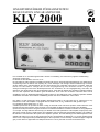
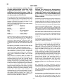
LINEARVERSTÄRKER FÜR BASISSTATION
BASE STATION LINEAR AMPLIFIER
KLV 2000
Der KLV2000 ist ein Hochleistungsverstärker welcher in Verbindung mit Transceivern jeglicher Sendeleistung
eingesetzt werden kann.
Er arbeitet auf den Bändern 160 m bis 10 m.
Der automatische Lüfter arbeitet mit variabler Drehzahl und sorgt für ausreichende Röhrenkühlung. Eine elektronische
Vorspannung trennt die Röhren bei Empfang ab, womit Störungen und unnötige Wärmeverlustleistung vermieden
werden. Mittels einer Schutzschaltung wird ein Überschreiten des maximalen Gitterstroms vermieden, damit die
Röhren im Falle falscher Justage oder zu hoher Eingangsleistung nicht überlastet werden. Die großen
Anzeigevorrichtungen teilen Ihnen die Basisparameter des Verstärkers, die HF-Ausgangsleistung, das SWR, den
Gitterstrom, den Anodenstrom oder die Anodespannung mit, womit das der Betrieb des Verstärkers ständig kontrolliert
wird. Es wird empfohlen das Handbuch ganz durchzulesen, bevor man den Verstärker in Betrieb nimmt. Durch
sorgfältiges Lesen der Bedieunungsanleitung werden Fehler bei der Bedienung sowie mögliche irreparable Schäden
an Bauteilen vermieden. Bei korrekter Handhabung können Sie den KLV2000 viele Jahre nutzen.
KLV 2000 is a high performance linear amplifier designed and made to be used with any HF transceivers in any
transmission mode. This amplifier is equipped with two 572B triode, in AB
2
classification with grounded grid.
It is operated in all the bands 160 m. to 10 m.
A variable speed inner fan provides the tubes cooling, an electrical circuit controls its operation. A bias electronic circuit
provides the tubes disconnection when receiving so that avoiding any disturb and unnecessary tube dissipation.
A protection circuit prevents the max grid current to be exceeded to avoid tubes overload in case either of wrong adjustment
or over input. The large indicator devices keep you advised on the basic parameters of the amplifier, output power, SWR,
grid current, anodic current or anodic tension are indicated to control continuously the amplifier operation. The reading of
the manual is recommended in all its parts before amplifier operation, the under standing of the detailed operation of the
amplifier will enable you to get the best performance and to avoid mistakes in adjustment or in controls positioning that
cause a loss of output power and possible damages on the components, even irreversibly. A careful and proper usage will
give you the chance to appreciate KLV 2000 performance for a lot of years with no need of technical service.

Index - Index
1 Einleitung - Introduction
2 Index - Index
3 Technische Daten, Sicherheitshinweise, Garantie - Specifications, Cautions, Warranty
4 Frontbeschreibung - Front description
5 Ansicht der Rückseite - Rear description
6 Tabelle 1 - Table 1
Abb. 3
Deutsch
7 Installation
- Auspacken und Kontrolle
- Installation
- Anschluss an das Netz
- Antenne
- Erdungsanschluss
8 Abb. 4 Verbindungen KLV 2000
Abb. 5 Netzspannungen
9 Betrieb
10 Abb. 6
ENGLISH
11 Installation
- Removal from package and inspection
- Installation
- Network connection
- Antenna
- Earth
12 Pic. 7 Connections to KLV 2000
Pic. 8 Connection to supply net
13 Operation
14 Pic. 9
- 2 -

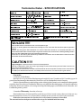
Technische Daten - SPECIFICATIONS
Ω
Ω
Ω
Ω
Vorsicht !!!!!
Das Gerät arbeitet im Gehäuseinneren mit Hochspannungen.
Es kann zu einem gefährlichen elektrischen Schlag kommen, wenn der Benutzer Hochspannungskreise
berührt.
Lassen Sie alle jegliche Servicearbeiten von einem Fachmann ausführen. Im KLV2000 befinden sich
Sicherheitsschalter welche die Hochspannungskreise unterbrechen, diese sollten unbedingt betätigt werden
bevor Sie den Gehäusedeckel für Servicearbeiten abnehmen.
Ziehen Sie vor der Öffnung des Gehäuses grundsätzlich den Stecker aus der Steckdose und blockieren Sie
keinesfalls die Sicherheitsschalter.
CAUTION !!!!!
High voltages are present within the cabinet of this apparatus.
Harmful or fatal electric shock will result if high voltage circuits are touched by the user. Refer for all service
work to an experienced technician.
Safety interlock switches are included in the KLV 2000 to disconnect power if the top cover is removed. Do
not attempt to defeat these switches, and always disconnect the AC line before opening the cabinet
- 3 -
Garantie:
24 Monate ab Kaufdatum.
Beachten Sie die gesetzlichen Bestimmungen bezüglich Linear Verstärkern. Bei Verstößen gegen die
gesetzlichen Bestimmungen übernimmt der Hersteller sowie der Fachhändler keinerlei Garantie.
Falls die Sicherheitshinweise nicht befolgt werden erlischt jegliche Garantie sowie sämtliche Rechtsansprüche
gegenüber dem Herrsteller und Fachhändler. Röhren sowie äußerliche Beschädigungen (z.B. durch den Kunden
verursachte Kratzer am Gehäuse oder sonstige mutwillige Beschädigungen) sind nicht durch die Herrsteller- und
Fachhändlergarantie gedeckt.
24 monthes Warranty, from date of receipt.
Remind that the use of linear amplifiers is ruled by special laws in each country, that are to be known. Any
way the manufacturer decline every responsibility coming from uncorrected use respect to the actual rules.
If the above instructions are not observed, every form of warranty is cancelled.
The external and estetical parts and the tubes are never included in the warranty.

- 4 -
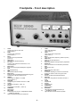
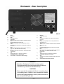
Frontplatte - Front description
1) LOAD
Justieren der Last an der Linear
(siehe Tabelle 1)
2) TUNE
Justieren des Anodenteils
(siehe Tabelle 1)
3) Band
Auswahl des Frequenzbands
(siehe 15)
4) SWR Sens.
SWR-Ende der Skaleneinstellung
5) Pre Tune
Justieren des Antennenvorverstärkers in der
Arbeitsfrequenz
6) Multimeter
Es wird die anzuzeigende Maßgröße eingestellt
7) Watt
HF-Ausgangleistung
8) SWR
Stehwellenverhältnis-Anzeige
9) Multimeter
Zeigt bei Position gemäß 6 die Anodenspannung, den
Anodenstrom oder den Gitterstrom an.
10) DIR/REF
Wählschalter für Messen von SWR
direkt/reflektiert 8
11) Delay/ON
Verzögerung beim Arbeiten ohne PTT in SSB
12) Lin/ON
Verstärker einschalten (siehe 16)
13) Pre/ON
Vorverstärker einschalten (siehe 16)
14) POWER/ON
Netzschalter
15) Meter/MHz
Lichtanzeiger des durch 3 ausgewählten Bandes
16) A, Lin ON, TX, Pre ON
LED zur Betriebsanzeige des Verstärkers.
1
2
3
4
5
6
7
8
9
10
1
1
12
13
14
15
16
1) LOAD
Linear load adjustment
(refer to table 1)
2) TUNE
Linear anodic section adjustment
(refer to table 1)
3) Band
Linear working band (frequency) selection (see15)
4) SWR Sens.
SWR end of scale adjustment
5) Pre Tune
Antenna preamplifier working frequency adjustment
6) Multimeter
Select the measure to be indicated by multimeter
7) Watt
Output power level
8) SWR
Output stationary wawes level
9) Multimeter
It indicates, dependig on position of 6, the anodic
tension, the anodic current or the grid current
10) DIR/REF
Selector of SWR direct/reflected measure
11) Delay/ON
Delay when using without connection with PTT in
SSB
12) Lin/ON
Amplifier ON
13) Pre/ON
Preamplier ON
14) POWER/ON
Network switch
15) Meter/MHz
Light indicator of the selected band by 3
16) A, Lin ON, TX, Pre ON
Light indicators of linear status of operation
Abb. 1

- 5 -
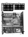
1) Netz
Netzkabel
2) GND
Erdungsanschluß
3) Ventilator
Belüftungsgitter (immer freihalten, niemals blockieren)
4) ALC
Diese RCA-Buchse wird für den
Transceiveranschluß der ALC-Regelung benutzt
5) PTT+
Eine Plusspannung über 6V schaltet das Senden der
Linear ein
6) PTT-
Ist dieser Eingang geerdet, aber mit einer Spannung
unter 4 V, geht die Linear auf Sendung
7) RTX
HF-Eingangsbuchse PL-Norm für den ansteuernden
Transceiver.
8) ANT
Anschlussbuchse für Antenne (PL-Norm) /
Ausgangsbuchse für HF-Leistung
9) Anschlüsse und Notizen (Ratschläge)
Rückwand - Rear description
1) Network
Supply cable input
2) GND
Connect the amplifier to the station ground bus at
this point
3) Fan
Fan grid (always keep it free of any materials that
could obstruct it)
4) ALC
This RCA jack is used for connection to the trasceiver
ALC control input
5) PTT+
A positive tension exceding 6V cause the commute
to linear transmission
6) PTT-
When this input in grounded, however with a tension
lower than 4 V, it causes commute to linear
transmission
7) RTX
The RF input from the transceiver should be
connected to this SO 239 connector
8) ANT
This SO 239 connector provides the RF output to the
antenna
9) Connections and notices (advices)
Vorsicht !!
Betreiben Sie diesen Verstärker nie ohne guten
Erdungsanschluß oder eine angeschloßene Antenne
oder Dummy Load an der Buchse ANT (8).
CAUTION
Never operate this equipment without connecting it to a
good earth ground. Likewise, never operate the amplifier
wthout having an antenna or dummy load connected to
the rear panel ANT jack (8)
Abb. 2
1
2
3
4
5
6
7
8
9

- 6 -
Tabelle 1
(Notizien für die Einstellung der Knöpe TUNE und LOAD )
Table 1
BAND
Freq
MHz
TUNE
LOAD
Our
YourOur
Your
10
12
15
17
20
30
40
80
160
28.0
Center
Center
Center
Center
Center
Center
Center
Center
Center
29.7
24.5
25.0
21.0
21.5
18.0
18.5
14.0
14.5
10.0
10.5
7.0
7.5
3.5
4.0
1.8
2.0
BAND
Freq
MHz
TUNE
LOAD
Our
YourOur
Your
Abb. 3

- 7 -
D
Ansicht des Geräts nach dem Kauf
ehmen Sie den KLV 2000 vorsichtig aus der
Verpackung und schauen Sie nach Schäden
(kleinere Kratzer am Lack fallen nicht hierunter,
da diese bereits bei der industriellen Fertigung auf
dem Fließband entstehen können).
Sollten Sie offensichtliche Beschädigungen am
KLV2000 finden, schreiben Sie einen
Fehlerbericht an Ihren Händler. Bewahren Sie die
Originalverpackung auf und beschädigen Sie
diese nicht. Für einen Austausch oder Service
Arbeiten wird oftmals die Originalverpackung
benötigt.
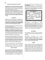
Installation:
Platzieren Sie den Verstäker nur an Stellen, an
denen eine freie Luftzirkulation gewährleistet ist.
Legen Sie keine Bücher, Papiere oder sonstige
Gegenstände auf die Ober- und Rückseite des
Verstärkers. Bei unzureichender Belüftung
kann der Verstärker Schaden erleiden.
Zur Erklärung der einzelnen Anschlüße sehen Sie
sich Abb. 2 auf Seite 5 an.
Die ALC-Buchse des Transceivers ist mit der ALC-
Buchse des KLV2000 zu verbinden. Der PTT-
Ausgang des Transceivers muss an den PTT-
Eingang des KLV2000 angeschloßen werden.
Wird dieser Anschluß nicht verwendet, regelt eine
Innenschaltung das Umschaltsignal. Zum Zwecke
der besseren Umschaltbedienung ist es hilfreich
den PTT-Eingang zu nutzen. Die beiden
erwähnten Buchsen sind vom Typ RCA.
Mit einem kurzen Koaxkabel RG-58A/U oder RG8-
A/U verbinden Sie den Ausgang des Transceivers
mit der Buchse RTX (7, Abb.2) des KLV 2000.
Für den Ausgang ANT (8, Abb.2) nehmen Sie
niemals ein dünnes Kabel wie z.B. das RG-58,
sondern ein leistungsstarkes Kabel, wie z.B. das
RG-8A/U, RG-213 /U oder entsprechendes.
Der für das Ansteuern des KLV 2000 zu
benutzende Transceiver muß 100 W PEP
Leistung haben damit die maximale
Ausgangsleistung des Verstärkers erreicht wird.
Netzanschluß:
Das im KLV 2000 sitzende Netzteil kann an einer
Netzspannung von 100/110/120/200/220/240 V
Wecks. ; 50/60 Hz, arbeiten. Vor dem Einstecken
des Netzsteckers beachten Sie den Aufkleber auf
der Geräterückwand (9, Abb.2) wegen der
richtigen Spannung. Zum Abändern der
Netzspannung schauen Sie auf Abb.8, oder auf
das Schaltbild.
Die Netzsicherung hängt von der Spannung ab.
Ihre Größe ist sehr wichtig: Für 100/110/120 V
Wechs. Muß sie 20 A haben und schnell
ansprechen; für 200/220/240 V Wechs. Muß sie
10 A haben und schnell arbeiten.
Der KLV 2000 ist an einen passenden
Netzstecker ohne Adapter und andere
Verbraucher anzuschließen, damit
Leitungserhitzungen vermieden werden. Die
Netzleiter dürfen nicht kleiner als 2,5 mm² für die
Wechselspannung 200/220/240 v sein, oder 10
AWG für 100/110/120 V Wecks. Falls sich bei
Gebrauch des KLV 2000 das Zimmerlicht
verdunkelt, ist der Netzanschluß ungeeignet.
ANTENNE:
Der KLV2000 ist an Antennen mit einer Impedanz
von 50 bis 75 Ohm auf der Betriebsfrequenz zu
betreiben.
Andernfalls benötigen Sie einen
Impedanzanpasser (Matchbox). Die am
Verstärker angeschlossenen Antennen müßen
eine hohe HF-Ausgangsleistung aushalten
können, andernfalls können Antenne, Vertärker
oder Transceiver beschädigt werden.
ERDE
Dieser Verstärker muss an die Stationserde
angeschlossen werden, wobei das Erdkabel nicht
länger als 3 Meter sein sollte. Dieses Kabel wird
mit der Buchse GND auf der Rückseite des
Verstärkers verbunden. Achten Sie auf eine gute
Stationserdung, da sonst Probleme beim
Empfang und mit elektrostatischen Aufladungen
entstehen können.auf den metallischen Teilen, die
ACHTUNG !!!!
Wird der Verstärker an einer
falschen Netzspannung
betrieben, kommt es zu Schäden.
Die Garantie deckt diese
Schäden nicht ab, auch wenn
eine falsche Sicherung
eingesetzt wurde.

*1'
B
*1'
- 8 -
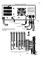
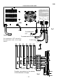
Abb. 4
D
Netz
Erdverbindung
Verbindung PTT
vom Trasceiver
zum ALC
zur antenne
GND
Die Verbindungen ALC und PTT sind
in der Bedienungsanleitung Seite 9
beschrieben.
Abb. 5
Netzumschaltungen Netztransformator
Verbindungen zum KLV 2000
nd

- 9 -
BETRIEB
Vor der Inbetriebnahme achten Sie auf
richtige Netzspannung, siehe Abb. 8 (die
Originaleinstellung wird auf den
Aufklebern hinten beschrieben; 9, Abb.2).
Achten Sie auf eine geeignete Antenne an
der Antennenbuchse (8, Abb.2).
Der mit dem KLV 2000 zu benutzende Transceiver muß
vor dem Betrieb mit der Linear eingestellt werden. Wird
RTX mit eingeschalteter Linear benutzt, muß der
Schalter 12 auf OFF (aus) stehen (Anzeiger Lin ON,
Schalter 16 auf OFF (aus), Abb. 1).
Stellen Sie die Bedienelemente am KLV 2000 wie folgt
ein (schauen Sie auf Abb. 1):
Power/ON ......................... OFF (aus)
Lin/ON ..............................OFF (aus)
Pre/ON..............................OFF (aus)
Multimeter......................... Va
Band ................................. bevorzugtes Band
TUNE ................................siehe 1, Seite 6
LOAD ................................siehe 1, Seite 6
SWR Sens ........................ 0 (linksherum).
Schalten Sie den Verstärker mit Power/ON ein (Stellung
ON = ein). Eine Verzögerung von 2-3 Sekunden ist
normal, achten Sie auf eine geeignete Justage des
Transceiver (Röhrengeräte), prüfen den Wert der
Anodenspannung unter <Verstärkerparameters>, wobei
der Zeiger etwa 2,5 auf der unteren Skala (Va) anzeigen
soll.
Ein anderer Anzeigewert könnte auf eine falsche
Netzspannung hindeuten, schalten Sie Alles aus und
sehen Sie sich Abb. 8 Spannungsregulierung an.
Achten Sie darauf, dass der Frequenzbandschalter (3.
Abb.1) auf dem richtigen Band steht. Schalten Sie
<MULTIMETER> (6, Abb.1) auf Ia, bringen den
Transceiverausgangsregler auf Minimum, schalten Lin/
ON (12, Abb.1) auf ON (ein) (Lin/ON 16, Abb.1, auf ON
schalten).
Stellen Sie die PTT-Taste am Mike des Senders auf
Senden, wonach der KLV 2000 auf Sendung geht, und
den Status mittels Licht TX (16, Abb.1) anzeigt. Drehen
Sie den Leistungsregler am Transceiver auf, bis eine
Anzeige von 200 mA (0,2 A) auf der Anzeige 9, Abb.1
erscheint; justieren den Knopf TUNE (2, Abb.1), bis
Sie die maximale HF-Ausgangsleistung am Wattmeter
(7, Abb.1) bekommen, was dem minimalen
aufgenommenen Anodenstrom (auf 9, Abb.1 zu sehen)
entspricht. Lassen Sie die PTT los und gehen wieder
auf Empfang. Warten Sie ein paar Augenblicke, drücken
erneut die PTT-Taste, und erhöhen die
Ausgangsleistung, bis Sie am Multimeter (9, Abb.1)
400 mA (0,4 A) ablesen; und drehen abwechselnd an
den Knöpfen TUNE und LOAD (2 und 1, Abb. 1), um
die maximale HF-Ausgangsleistung am Wattmeter zu
bekommen, lassen dann die PTT-Taste los.
ACHTUNG !!!
Bleiben Sie während der Abstimmung
nicht länger als 10 Sekunden auf Sendung
(gedrückte Taste) um die Endröhren nicht
zu überhitzen. Eine hoheHitzebelastung
kann zu einem frühzeitigen Ausfall der
Röhren führen.
Schalten die Anstuerleistung (RTX) Ihres Transceivers
auf ca. 100W PEP und überprüfen Sie nocheinmal
sorgfältig die Abstimmungen am Verstärker. Bei 100W
gibt der KLV2000 seine höchste Ausgangsleistung ab.
Während der Justierung und besonders während des
Gebrauchs muß der Gefahranzeiger A (Dreieck) (16,
Abb.1) aus sein; diese Leuchte zeigt entweder das
Überschreiten von 500 mA der Anodenstromaufnahme
an, oder den Schutz vor zu hohem Gitterstrom, was für
die Lebensdauer der Röhren gefährlich sein kann. Wird
während des Abstimmens der Gitterschutz
hereingenommen, nehmen Sie die Eingangsleistung
zurück, und erhöhen diese nur nach einer neuen
Justierung.
Die Einstellung der Knöpfe TUNE und LOAD für eine
maximale HF-Ausgangsleistung an einer Last von 50
Ω
findet sich in Tabelle 1, auf Seite 6.
Nun kann die Justierung des SWR-Meters
vorgenommen werden. Schalten Sie den Knopf 10,
Abb.1 (Dir/Ref) in Dir (die Anzeigevariation des
Wattmeter ist normal), drücken die PTT-Taste, und
drehen den Regler SWR Sens (4. Abb.1) auf, um den
Zeiger der SWR-Einrichtung (8, Abb.1) unten auf die
Skala zu legen, das ist die Stellung für unendlich,
bringen den Knopf 10 auf Ref, und nun zeigt die SWR-
Anzeige (8) das SWR fur den Ausgang des KV 2000.
Während des Betriebs des Verstärkers muß der Wert
des SWR akzeptabel bleiben, wobei niemals 3
überschritten werden, und möglichst unter 1,5
gemessen darf werden. Mit einem niedrigeren SWR
erhöht sich der Leistungstransfer, auch die von der
Antenne abgestrahlte Leistung, und ein SWR höher
als 3 kann gefährlich für die Lebensdauer der Röhren
werden.
Bei Gebrauch in SSB Justieren Sie die
Eingangsleistung auf einen aufgenommen Anodenstrom
von 0,2 bis 0,3 A,wenn Sie in das Mikrofon sprechen,
weil die Anzeigen im KLV2000 die mittlere
Anodenkreisaufnahme anzeigen, und der Spitzenwert
das Zweifache ist.
Bei Gebrauch in AM-FM-FSK justieren Sie die
Transceiverleistung auf einen Anodenstrom von 0,2 bis
0,3 A, wob ei der unmodulierte Träger und seine
Anwendung ohne Unterbrechungen (Empfang) auf eine
D

- 10 -
Zeit begrenzt werden muß, in der die Röhren abgekühlt
werden.
Das Multimeter (9, Abb.1) zeigt auch den Gitterstrom
an, der von der Einstellung des Ausgangskreises und
der Eingangsleistung abhängt. Der Gitterstrom darf 90
mA nicht übersteigen. Ein Schutzkreis macht den
Betrieb der Linear unmöglich, wenn dieser Wert
überschritten wird, wobei dieser Zustand durch
Einschalten des Gefahranzeigers (Dreieck 16, Abb.1)
angezeigt wird, auch der Betrieb des Verstärkers
unterbunden wird. Zum Neustarten des KLV 2000
bringen Sie den Knopf Lin/ON auf OFF (aus) (12,
Abb.1). Ein weiterer Grund für einen eintretenden
Schutzvorgang, wobei das entsprechende Licht angeht
und der KLV 2000 gestoppt wird, ist das nicht
ordnungsgemäße Arbeiten des Lüfters. Eine
elektronische Kontrolle am Lüftermotor zeigt eine
auftretende Anomalie auf dem Schutzkreis. In diesem
Zustand arbeitet das Neustarten des KLV 2000 mittels
des Schalter Lin/ON nicht, und man muss einen
Techniker beauftragen. Der Schutz tritt auch ein, wenn
die Linear eingeschaltet ist (ON), falls sich der Schalter
Lin/ON auf ON befindet (12, Abb.1), weil die
Lüfterdrehzahl ein paar Sekunden braucht, um den
festen Wert zu erreichen. In diesem Falle bringt man
am Schalter Lin/ON den KLV 2000 in den Neústart.
Der Schalter Delay/ON (11, Abb.1) brigt in der Stellung
ON eine Verzögerung von etwa 2 Sekunden ein, wenn
das Relais zum Umschalten freigegeben wird, was für
SSB und CW für den fall nötig ist, dass einer der
rückwärtigen Stecker PTT (5 oder 6, Abb.2) nicht
benutzt wird, worauf der KLV 2000 mit dem Innen VOX-
Kreis umschaltet. Die Verzögerung dient dazu ein
standby des Antennenrelais zu vermeiden, wenn das
Eingangssignal währen der kurzen
Senderunterbrechung Null ist.
Der Antennenvorverstärker wird mittels des Schalters
Pre/ON (13, Abb.1) eingebracht. Dazu Justieren Sie
den Vorabstimmer (5, Abb.1) auf die benutzte Frequenz.
Ist der Verstärker aus, stimmen Sie auf ein Signal nahe
der Arbeitsfrequenz im Empfänger ab, schalten den
Vorverstärker auf ON (ein), und drehen den Knopf Pre
Tune langsam in die eine oder andere Richtung, um
den maximalen Ausschlag am S-Meter des Empfänger
zu bekommen.
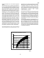
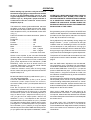
Der Vorverstärker arbeitet als ein Passbandkreis, mit
einer begrenzten Breite. Beim Frequenzabstimmen (16,
Abb.1) verstärken Sie das Signal von 30 MHz bis 9,5
MHz, und schwächen es von 9,5 bis 6,5 MHz ab, wie
auf dem Schaubild der Abb.6 zu sehen. Auf diese
Weise wird auf dank des begrenzten Paßbands die
Intermodulation lauter Signals auf Nachbarfrequenzen
vermindert, auch werden schwache Signale auf den
hohen Bändern angehoben.
dB
Band
0
-10
+10
+15
+20
+25
-5
+5
10m12m15m17m20m30m40m
Abb. 6
Gain versus frequency preamplifier curve chart
D

G
Removal from package and inspection
Carefully remove the KLV 2000 from its package and
check for damages on the linear.
Carefully move any control and switch to check they
are regularly working. In case any damages is found,
prepare a detailed report to be immediately sent to your
supplier. Keep the complete package to be re-used if
required. The original package must be used if the piece
has to be returned to a service centre.
Installation
The amplifier needs a lot of room all around so that air
can freely circulate, enabling a proper ventilation to all
components.Do not put, books, paper or any other
object on the top of KLV 2000, do not create any
obstruction to the back grill.
A limited and difficult ventilation can severely
damage the linear.
For details about the connections please refer to pic.
7.
The ALC input of the transceiver has to be connected
to the ALC output (4 pic. 2) of KLV 2000. The PTT
output of the transceiver has to be connected to the
PTT input (6 pic.2, seldom 5 pic. 2) of the linear. When
this connection is not used an internal circuit provides
the commuting signal. For a better control on
commuting it is any way advisable the usage of PTT
input.
Both the above mentioned connectors are of RCA type.
Use a short coaxial cable RG 58 A/U or RG 8 A/U type
for the interconnection of the output of the transceiver
to the RTX connector (7 pic. 2) of the KLV 2000. For
the ANT output (8 pic. 2) connection to the antenna
never use a thin cable such as RG 58, use only a cable
able to bear the output power, adequate cable are RG
8 A/U, RG 213 /U or equivalent.
The transceiver used to drive the KLV 2000 has to be
able to provide 100 W PEP to get the max output power
of the linear.
Network connection
The supply for the KLV 2000 already included with the
set, is able to work on network tension 100/110/120/
200/220/240 Vac 50/60 Hz. Before connecting the
network plug be assured that the tension is the correct
one as written on the sticker on the back (9 pic. 2).
To modify the working tension refer to Picture 8 or to
electric scheme.
The network fuse depends on the supply tension.
Its size is very important, for 100/110/120 Vac it as to
be of 20 A fast, for 200/220/240 Vac it has to be of 10 A
fast.
An inner delay circuit gives a limit to the pick of current
when switching on.
The KLV 2000 has to be connected to a plug of an
independent network, without any adaptor or different
devices that could cause heating of the connections,
so that they could be damaged. Conductor of the
network circuit does not have to be lower than 2,5 mm²
for 200/220/240 Vac tension or 10 AWG for 100/110/
120 Vac tension. If during the use of KLV 2000 a
considerable lowering of the lights placed in the same
room as the amplifier is noted, the network connector
has not a sufficient section to use safely the same.
Antenna
The KLV 2000 is designed to be used with antennas
featuring a load of 50 75 Ω on the working frequency.
In case you are using an antenna with different features
the use of any impedance adaptor or of an impedance
matcher is advisable because they are able to bring
the impedance seen by the amplifier to its output within
the required limits. Remind that devices receiving from
the amplifier must bear its output power because when
they are not adequate irreparable damages can be
caused.
Earth
This amplifier has to be connected to the earth of the
radio station, using a cable with the proper section, not
longer that 3 m. The earth cable has to be connected
to the suitable back pin (2 pic. 2) verify that the earth of
the station is of the best quality, this will avoid problems
when receiving, will prevent the accumulation of static
charges and will avoid zones with high RF tension in
transmission on the metal parts that can be touched.
Attention !!!!
The use of the amplifier with a not
proper network tension creates
permanent damages The warranty
does not cover damages given by a
not proper supply or by a not proper
fuse.
- 11-

*1'
B
*1'
- 12 -
Fig 7
G
Network plug
Earth
To ricetranceiver
PTT
To ricetranceiver RF plug
To ALC plug
To antenna
GND
For connection of PTT and ALC to
the transceiver refer to its usage
section
Fig 8
Possible connections to the primary
of the trasformer of supply
Connections to KLV 2000

G
OPERATION
Before starting any operation verify the tension in
the network supply plug corresponds to the tension
as set up in the KLV2000 supply, see pic. 8, (the
original adjustment is described on the back
stickers 9 pic. 2). Verify that a proper antenna is
connected to the ant connector of the Linear
Amplifier (8 pic.2).
The transceiver, used to guide the KLV2000, has to be
set before it can work coupled with the linear. When
the RTX set is carried out with linear on, the 12 switch
has to be place on OFF ( Lin ON indicator, switch OFF
16 fig. 1).
Place the KLV2000 commands as<follows: (Refer to
picture 1):
Power/ON .................................... OFF
Lin/ON ......................................... OFF
Pre/ON ........................................ OFF
Multimeter.................................... Va
Band ............................................ Prefer Band
Tune ............................................ See...1 page 6
Load ............................................ See...1 page 6
SWR Sens.............................O Counter clock wise
Switch on the Amplifier by the command Power/ON
(Position ON), A 2-3 seconds delay before a complete
lightening of the instruments is normal, be assured to
get a proper adjustment of the transceiver (TUBE
DEVICES), check the level of anodic tension on
<Amplifier Parameters > the pointer should indicate
aprox 2,5 on the lower scale (Va).
A different indication could mean a wrong supply
tension, switch everything OFF and check the tension
adjuster setup Pic.8
Be assured that the frequency band selector (3 pic. 1)
is on the appropriate band.
Commute <MULTIMETER> (6 Pic.1) on Ia, put the
transceiver power output control on minimum,
commute Lin/ON (12 Pic.1) on ON (switch ON of Lin/
ON 16 pic.1).
Push the microphone PTT to the transmitter on
transmission, KLV2000 commutes in transmission and
show the condition by the TX light (16 pic.1). Increase
the transceiver power control till reading 200 Ma (.2
Amp) on device 9 pic.1, adjust tune control (2 pic.1)
until you get the max output power read on the
wattmeter (7 pic.1), it corresponds to the minimum
absorbed anodic current (shown on 9 pic.1). Release
PTT and enter reception again. Wait for few moments,
push again PTT increase the power until you read on
the multimeter (9 pic.1) 400mA (.4 Amp) and adjust
alternatively the commands TUNE and LOAD (2 and 1
pic.1) to get the max output power on wattmeter, release
PTT.
ATTENTION !!! WHEN ADJUSTING DONT STAY IN
TRANSMISSION (KEY DOWN) FOR OVER 10
SECONDS WITHOUT INTERRUPTING BY MEANS
OF A RECEPTION PHASE LONG ENOUGH TO
PERMIT THE COOLING OF THE END TUBES. THE
EXCESSIVE HEATING CAUSES THE PREMATURE
EXHAUSTION OF THE TUBES.
Bring excitatory power (RTX) to about 100 W PEP and
check the linear adjustment. In this status the KLV 2000
provides its max output power, that has to correspond
to the dip of the anodic current (Ia).
During adjustment, and especially during usage, the
danger indicator
A (16 pic. 1) has to be off, this light
indicates either the exceeding of 500 mA of anodic
current absorption or the protection for too high grill
current that can be dangerous for the tubes life. When
during tuning the grill protection is entered, decrease
input power and increase again only after adjustment.
The position of Tune and Load commands for the max
output power on a 50 Ω load is indicated in the Table 1,
page. 6.
Now the SWR-meter adjustment can be effected.
Commute button 10 fig. 1 (Dir/Ref) in Dir (the variation
of indication of wattmeter is normal), press PTT button
and increase SWR Sens. control (4 pic. 1) to put the
pointer of SWR devices (8 pic. 1) to the bottom of the
scale, position ∞, bring the command 10 on Ref, now
the indication of SWR devices (8) shows the SWR at
the KLV 2000 output.
During the use of the amplifier, the level of the stationary
waves (SWR) has to remain to an acceptable level,
never exceeding 3 and possibly lower than 1,5. A lower
SWR increase the power transfer therefore also the
antenna irradiated power, a SWR higher than 3 can be
dangerous for the life of the tubes.
When using in SSB, adjust the input power for an
absorbed anodic current of 0.2 0.3 A speaking at the
microphone, because the KLV 2000 devices indicates
the medium absorption of the Plate circuit, and the peak
are double of this.
For usage in AM FM FSK adjust the transceiver
power for an anodic current of 0.2 0.3 A, the carrier
not modulated and its usage without breaks (reception)
has to be limited to time sufficient to get the tubes
cooled down.
- 13 -

The multimeter (9 pic.1) indicates also the grid current,
it depends on the set-up of the output circuit and the
input power. The grid current does not have to exceed
90 mA. A protection circuits makes the linear usage
impossible when this value is exceeded and indicates
this condition switching ON the danger indicator A (16
pic. 1) and preventing the linear operation, to restart
the KLV 2000 operation bring the command Lin/ON on
OFF (12 pic. 1). Additional reason for the protection to
be entered - therefore the lightening of the
corresponding light and the KLV 2000 stoppage is
the non proper operation of the cooling fan. An
electronic control on the fan motor shows an eventual
anomaly on the protection circuit in this condition the
restarting of KLV 2000 operation by means of the Lin/
ON command is not working, and a technician has to
be contacted. The protection is entered also when the
linear is switched ON, if the command Lin/ON is on
position ON (12 pic. 1), because the fan speed required
few seconds to reach the fixed level, in this case the
operation on command Lin/ON make the KLV 2000
restart.
The Delay/ON command (11 pic. 1) enters, in position
ON, a delay of about 2 seconds when releasing the
relay of commuting, necessary in SSB an CW in the
case when one of the back plug PTT (5 or 6 pic. 2) is
not used so that KLV 2000 commutes by the inner VOX
circuit. The delay is for avoiding the antenna relay to
standby when the input signal is zero during the short
transmission break.
The antenna preamplifier is inserted by means of the
command Pre/ON (13 pic. 1). To use, adjust the pre-
tune command (5 pic. 1) to the used frequency. When
the amplifier is off, syntonize a signal close to the
working frequency in the receiver, switch the
preamplifier ON and slowly turn the command Pre Tune
in a direction or the other to find the max deflection
position of the s-meter of the receiver.
The preamplifier works as a Pass-band circuit, with a
limited width. Across tuning frequency (16 pic. 1) amplify
the signal 30 to 9,5 MHz and lower it down 9,5 to 6,5
MHz as per the diagram in pic. 9, this way it enables,
also thank to the limited passing-band, to decrease the
intermodulation of loud signals on adjacent frequencies
and to amplify the low signals in high bands.
dB
Band
0
-10
+10
+15
+20
+25
-5
+5
10m12m15m17m20m30m40m
Fig 9
Gain versus frequency preamplifier curve chart
G
- 14 -
-
 1
1
-
 2
2
-
 3
3
-
 4
4
-
 5
5
-
 6
6
-
 7
7
-
 8
8
-
 9
9
-
 10
10
-
 11
11
-
 12
12
-
 13
13
-
 14
14


in anderen Sprachen
- English: RM KLV 2000 User manual
Verwandte Artikel
Andere Dokumente
-
 RM Italy KLV 1000 P Benutzerhandbuch
-
RM Italy KL 505V Bedienungsanleitung
-
Silvercrest 56861 Benutzerhandbuch
-
Kenwood TS-780 Benutzerhandbuch
-
Albrecht Tectalk Action Datenblatt
-
Albrecht AE7500 Benutzerhandbuch
-
PRESIDENT Lincoln Bedienungsanleitung
-
SCS PACTOR III Installationsanleitung
-
-
 Kuhne electronic TR144-PRO Benutzerhandbuch

