
Australia
Phone +61 3 9497 4100
Belgium/Luxembourg
Phone +32 (0)2 466 55 66
Brasil
Phone +55 11 3215-4900
Canada
Phone +1(952) 941-6780
Ceská Republika
Phone +420 2 57 91 18 50
China
Phone +852-2763 6966
Danmark
Phone +45 45 82 64 00
Deutschland
Phone +49 211 5301-301
España
Phone +34 93 480 31 00
France
Phone +33 1 64 62 35 00
Great Britain
Phone +44 (0)1727 831121
India
Phone +91–22–4033 8333
Israel
Phone +972-4-999-0590
Italia
Phone +39 02 27 43 41
Japan
Phone +81 (0)3 3358 1341
Magyarország
Phone +36 1 371 2680
Nederlands
Phone +31 (0)30 229 25 44
Österreich
Phone +43 (0)22 36 62 28 8-0
Norge
Phone +47 67 81 50 00
Polska
Phone +48 22 837 40 50
România
Phone +40 356 171 120
Russia
Phone +7 495 775 05 30
Schweiz
Phone +41 41 619 29 39
Singapore
Phone +65 6744 3732
Slovenija
Phone +386 (0)1-47 69 990
South Africa
Phone +27 11 472 3733
South Korea
Phone +82-2 786 6321/4
Suomi
Phone +358-9-25 15 800
Sverige
Phone +46 10 110 10 00
Taiwan
Phone +886 2 2375-6288
Türkiye
Phone +90 216 528 50 00
United Arab Emirates
Phone +971 4 8865 878
USA/México
Phone +1(952) 941-6780
BZ int37
Please find detailed addresses and additional representatives and agencies in
all major industrial nations at www.sick.com
Subject to change without notice
Irrtümer und Änderungen vorbehalten
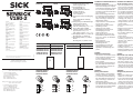
VTF180-2 und VTE180-2 Reflexions-
Lichttaster energetisch
• Einsatzbedingungen wie Größe und
Remissionsvermögen des Objekts
sowie Hintergrundeinflüsse überprü-
fen und mit der Empfindlichkeits-
kennlinie des VTF180-2/VTE180-2
Typs vergleichen.
• Taster auf das Tastgut ausrichten.
In horizontaler/vertikaler Richtung
Ein-/Ausschaltpunkt (Wechselan-
zeige-LED orange) ermitteln und
Mittelstellung wählen.
• Objekt entfernen und Empfindlich-
keit auf „max.“ stellen.
• Hintergrund wird nicht erkannt:
Einstellung beendet.
• Hintergrund wird erkannt:
Empfindlichkeit reduzieren, bis
Schaltausgang wechselt.
Objekt positionieren.
• Wenn Objekt nicht erkannt wird,
Empfindlichkeit (Drehknopf) Rich-
tung „max.“ drehen, bis Schaltaus-
gang wechselt.
• Objekt entfernen.
Schaltausgang wechselt:
Einstellung beendet.
• Schaltausgang wechselt nicht:
Hintergrundeinfluss zu stark.
Applikation und Einstellung über-
prüfen.
VL180-2
Reflexions-Lichtschranke
• Lichtschranke und Reflektor aufein-
ander ausrichten. Reflektor P250
im Lieferumfang enthalten.
Der rote Lichtfleck ist auf dem Re-
flektor sichtbar.
• In horizontaler/vertikaler Richtung
Ein-/Ausschaltpunkt (Wechselan-
zeige-LED orange) ermitteln und
Mittelstellung wählen.
VSE180-2
Einweg-Lichtschranke
• Sender VS180-2 und Empfänger
VE180-2 aufeinander ausrichten.
• In horizontaler/vertikaler Richtung
Ein-/Ausschaltpunkt (Wechsel An-
zeige-LED orange) ermitteln und
Mittelstellung wählen.
• Für exakte Positionieraufgaben und
zum Erkennen kleiner oder transpa-
renter Objekte ggf. die Empfindlich-
keit (Drehknopf) reduzieren.
8014796 1111 GO
V180-2
V180-2
Kunststoff Metall
Kunststoffgehäuse Metallgehäuse
Plastic housing Metal housing
VTF180-2P/Nxxx17 VTF180-2P/Nxxx12
VTE180-2P/Nxxx47 VTE180-2P/Nxxx42
VTE180-2P/Nxxx87 VTE180-2P/Nxxx82
VE180-2P/Nxxx37 VE180-2P/Nxxx32
VL180-2P/Nxxx36 VL180-2P/Nxxx31
VTF180-2P/N424xx
VTE180-2P/N424xx
VL180-2P/N424xx
VE180-2P/N424xx
VS180-2D023xx VTF180-2P/N411xx
VTE180-2P/N411xx
VL180-2P/N411xx
VE180-2P/N411xx
VS180-2D013xx
70.2
6
62.9
Ø 16.6
9.3
34 2
56.8
0.4
0.4
7
7
M18x1
Ø 16.6
2
34
60.5
60.5
2
56.8
M18x1
6.2
22
6.2
22
234
5
6
134
5
3
5
4
VTF180-2 and VTE180-2 Photo-
electric proximity sensors energetic
•
Check the application conditions
such as size and reflectance capa-
city of the object as well as back-
ground influences and compare with
the sensitivity characteristic curve of
the VTF180-2/VTE180-2 type.
• Direct sensor onto the object to
be probed. In the horizontal/vertical
direction, determine the on/off
switching point (change of the LED
orange indicator) of the signal
strength indicator and select the
central position.
• Remove object and set sensitivity
to “max.”.
• Background is not detected:
Setting is completed.
• Background is detected: reduce
the sensitivity until the switching
output changes.
Position object.
• If object is not detected, turn the
sensitivity (rotary knob) in the
direction “max.” until the switching
output changes.
• Remove object.
Switching output changes:
Setting is completed.
• Switching output does not change:
Background influence is too strong.
Check application and setting.
VL180-2
Photoelectric retro-reflective sensor
• Align photoelectric sensor and
reflector to one another. Reflector
P250 supplied with delivery. The red
light spot is visible on the reflector.
•
In the horizontal/vertical direction,
determine the on/off switching point
(change of the LED orange indicator)
and select the central position.
VSE180-2
Through-beam photoelectric
sensors
• Align sender VS180-2 and receiver
VE180-2 to one another.
•
In the horizontal/vertical direction,
determine the on/off switching point
(change of the LED orange indicator)
and select the central position.
• If necessary, reduce the sensitivity
(rotary knob) for exact positioning
tasks and for detecting small or
transparent objects.
1
L+
M
NC
NC
3
4
2
brn
blu
wht
brn
blu
L+
M
Adernfarben: 1/brn = braun; 2/wht = weiß;
3/blu = blau; 4/blk = schwarz
1)
L/D, Steuerleitung: Schaltart
L/D = + U
V
: hellschaltend L.ON
L/D = 0 V: dunkelschaltend D.ON
Steuerleitung L/D offen:
NPN = hellschaltend L.ON
PNP = dunkelschaltend D.ON
Wiring colors: 1/brn = brown; 2/wht = white;
3/blu = blue; 4/blk = black
1)
L/D, switching type: control line
L/D = + U
V
: lightswitching L.ON
L/D = 0 V: darkswitching D.ON
Switching type control line L/D open:
NPN = lightswitching L.ON
PNP = darkswitching D.ON
1
L+
M
Q
L/D
3
4
2
brn
blu
blk
wht
1)
brn
blu
blk
wht
L+
M
Q
L/D
1)
Kunststoffgehäuse Metallgehäuse
Plastic housing Metal housing
VS180-2Dxxx36 VS180-2Dxxx31
70.2
62.9
Ø 16.6
9.3
34 2
56.8
0.4
0.4
M18x1
Ø 16.6
2
34
60.5
60.5
2
56.8
M18x1
6.2
24
234
5
134
5
4
7
4
7
6.2
24
Gerätestecker M12, 4-polig
Device plug M12 4-pin
Anschlussleitung 2 m
Connecting cable 2 m
Empfindlichkeitseinsteller 270°
(nicht bei VS180-2)
Sensitivity control 270°
(not for VS180-2)
Anzeige-LED orange: Schaltausgang
aktiv
Orange LED indicator: switching
output active
Anzeige-LED grün, Stabilitätsanzeige:
LED leuchtet permanent:
Lichtempfang < 0,9 / > 1,1
LED aus: Lichtempfang> 0,9 ... < 1,1
Green LED indicator, Stability
indicator: LED lights continuously:
Light reception < 0.9 / > 1.1
LED off: light reception > 0.9 ... < 1.1
Befestigungsmuttern (2 x); SW22, PC
Mounting nuts (2 x); SW22, PC
Befestigungsmuttern (2 x); SW24,
Metall
Mounting nuts (2 x); SW24, metal
®

Technische Daten/Technical data VTF180-2P/Nxxx1x VTE180-2P/Nxxx4x VTE180-2P/Nxxx8x VL180-2P/Nxxx3x VS180-2Dxxx3x VE180-2P/Nxxx3x
Tastweite (TW) / Sensing distance (SD) / 1 ... 140 mm 0 ... 450 mm 1 ... 1100 mm 0.05 ... 7.0 m (PL80A) 0 ... 28 m 0 ... 28 m
Reichweite (RW) typ. max. sensing range (SR) typ. max.
Betriebstastweite / Operating distance / 1 ... 100 mm 1 ... 400 mm 1 ... 800 mm 0.05 ... 6.0 m (PL80A) 0 ... 20 m 0 ... 20 m
Betriebsreichweite operating range 0.05 ... 4.5 m (PL250)
1)
Lichtfleckdurchmesser/ Light spot diameter/ ~8 mm/100 mm ~20 mm/400 mm ~30 mm/800 mm ~400 mm/6.0 m ~1100 mm/20 m –
Entfernung
2)
distance
2)
Versorgungsspannung U
V
3)
Supply voltage V
S
3)
DC 10 ... 30 V DC 10 ... 30 V DC 10 ... 30 V DC 10 ... 30 V DC 10 ... 30 V DC 10 ... 30 V
Ausgangsstrom I
max.
Output current I
max
100 mA 100 mA 100 mA 100 mA – 100 mA
Signalfolge min. Signal sequence min. 1000/s 1000/s 1000/s 1000/s – 1000/s
Ansprechzeit Response time 0.5 ms 0.5 ms 0.5 ms 0.5 ms – 0.5 ms
Schutzart (IEC 144) Enclosure rating (IEC 144) IP 67 IP 67 IP 67 IP 67 IP 67 IP 67
VDE-Schutzklasse VDE protection class
Schutzschaltungen
4)
Circuit protection
3)
A, B, C A, B, C A, B, C A, B, C A A, B, C
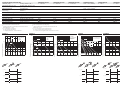
VTF180-2
Funktionsreserve/operating reserve
1)
VL180-2: Reflektor P250 im Lieferumfang enthalten
2)
Bei Betriebstastweite/Betriebsreichweite
3)
Grenzwerte, Betrieb in kurzschlussgeschütztem Netz max. 8 A
Restwelligkeit max. ± 10 %
4)
A = U
V
-Anschlüsse verpolsicher
B = Ein-/Ausgänge verpolsicher
C = Ausgange überstrom- und kurzschlussfest
1)
VL180-2: supplied with reflector P250
2)
With operating distance/operating range
3)
Limits, operation in short-circuit protected network max. 8 A
Ripple max. ± 10 %
4)
A = V
S
connections reverse polarity protected
B = inputs/outputs reverse polarity protected
C = outputs protected against excess current and short circuits
VTE180-2 VL180-2 VSE180-2
Funktionsreserve/operating reserve
Funktionsreserve/operating reserve
Funktionsreserve/operating reserve
Funktionsreserve/operating reserve
(m) 1 2 3 4 5 6 7 8
100
2
10
1
VL180-2
- D mit Polarizationsfilter
- D with polarizing filter
PL80A
PL250, PL40 A , PL50 A , C110A
PL30 A , PL31A
PL20A
P45
Diamond
G r ade
(m) 10 20 30
100
2
10
1
VSE180-2
(mm) 100 200 300 400 500
100
2
10
1
VTE180-2
scr.: 450 mm
HGU
BGB
90 %
18 %
6 %
(mm) 200 400 600 800 1.000 1.200
100
2
10
1
VTE180-2
scr.: 1.100 mm
energetisch
energetic
90 %
18 %
6 %
(mm) 20 40 60 80 100 120 140 160
2
10
1
VTF180-2
scr.: 140 mm
HGU
BGB
90 %
18 %
D
Q (PNP)
Q (NPN)
D
L
1
0
1
0
1
0
L
1
0
D
Q (PNP)
Q (NPN)
D
L
1
0
1
0
1
0
L
1
0
D
Q (PNP)
Q (NPN)
L
L
1
0
1
0
1
0
1
0
D
-
 1
1
-
 2
2


Verwandte Artikel
-
SICK VTB180-2 Photoelectric proximity switch Bedienungsanleitung
-
-
-
-
-
-
-
-
-