Mitsubishi MSZ-DM35VA Bedienungsanleitung
- Kategorie
- Split-System-Klimaanlagen
- Typ
- Bedienungsanleitung
Dieses Handbuch eignet sich auch für

English
Deutsch
Français
Nederlands
Español
Italiano
∂ÏÏËÓÈο
Português
Dansk
Svenska
Türkçe
Русский
INSTALLATION MANUAL
For safe and correct use, please read this installation manual thoroughly before installing the air-conditioner
unit.
INSTALLATIONSHANDBUCH
Zum sicheren und ordnungsgemäßen Gebrauch der Klimaanlage das Installationshandbuch gründlich
durchlesen.
MANUEL D’INSTALLATION
Veuillez lire le manuel d’installation en entier avant d’installer ce climatiseur pour éviter tout accident et vous
assurer d’une utilisation correcte.
INSTALLATIONSMANUAL
Läs denna installationsmanual noga för säkert och korrekt bruk innan luftkonditioneringen installeras.
INSTALLATIEHANDLEIDING
Voor een veilig en juist gebruik moet u deze installatiehandleiding grondig doorlezen voordat u de airconditioner
installeert.
MANUALE DI INSTALLAZIONE
Per un uso sicuro e corretto, leggere attentamente questo manuale di installazione prima di installare il condizionatore
d’aria.
MANUAL DE INSTALACIÓN
Para un uso seguro y correcto, lea detalladamente este manual de instalación antes de montar la unidad de
aire acondicionado.
E°XEIPI¢IO O¢H°IøN E°KATA™TA™H™
°È· ·ÛÊ¿ÏÂÈ· Î·È ÛˆÛÙ‹ ¯Ú‹ÛË, ·Ú·Î·Ï›ÛÙ ‰È·‚¿ÛÂÙ ÚÔÛ¯ÙÈο ·˘Ùfi ÙÔ ÂÁ¯ÂÈÚ›‰ÈÔ ÂÁηٿÛÙ·Û˘
ÚÈÓ ·Ú¯›ÛÂÙ ÙËÓ ÂÁηٿÛÙ·ÛË Ù˘ ÌÔÓ¿‰·˜ ÎÏÈÌ·ÙÈÛÌÔ‡.
MANUAL DE INSTALAÇÃO
Para segurança e utilização correctas, leia atentamente este manual de instalação antes de instalar a unidade
de ar condicionado.
INSTALLATIONSMANUAL
Læs venligst denne installationsmanual grundigt, før De installerer airconditionanlægget, af hensyn til sikker og
korrekt anvendelse.
MONTAJ ELK‹TABI
Emniyetli ve do¤ru biçimde nas›l kullan›laca¤›n› ö¤renmek için lütfen klima cihaz›n› monte etmeden önce bu
elkitab›n› dikkatle okuyunuz.
РУКОВОДСТВО ПО УСТАНОВКЕ
Для осторожного и правильного использования прибора необходимо тщательно ознакомиться с данным
руководством по установке до выполнения установки кондиционера.
Air-Conditioners OUTDOOR UNIT
MXZ-8A140VA
FOR INSTALLER
FÜR INSTALLATEURE
POUR L’INSTALLATEUR
FÖR INSTALLATÖREN
VOOR DE INSTALLATEUR
PER L’INSTALLATORE
PARA EL INSTALADOR
PARA O INSTALADOR
TIL INSTALLATØREN
°π∞ ∞À∆√¡ ¶√À ∫∞¡∂π ∆∏¡ ∂°∫∞∆∞™∆∞™∏
MONTÖR ‹Ç‹N
ДЛЯ УСТАНОВИТЕЛЯ
HFC
utilized
R410A

2
Contents
1. Safety precautions ................................................................................... 2
2. Installation diagram & parts ..................................................................... 3
3. Installation location .................................................................................. 4
4. Installing the outdoor unit ......................................................................... 6
5. Installing the refrigerant piping ................................................................. 6
6. Drainage piping work ............................................................................. 10
7. Electrical work ........................................................................................ 10
8. Test run .................................................................................................. 14
9. Special Functions .................................................................................. 15
1.2. Before installation (relocation)
Caution:
• Be extremely careful when transporting the units. Two or more persons are
needed to handle the unit, as it weighs 20 kg or more. Do not grasp the
packaging bands. Wear protective gloves to remove the unit from the pack-
aging and to move it, as you can injure your hands on the fins or other parts.
• Be sure to safely dispose of the packaging materials. Packaging materials, such
as nails and other metal or wooden parts may cause stabs or other injuries.
Warning:
• The unit must not be installed by the user. Ask a dealer or an authorized
technician to install the unit. If the unit is installed incorrectly, water leakage,
electric shock, or fire may result.
• For installation work, follow the instructions in the Installation Manual and use
tools and pipe components specifically made for use with R410A refrigerant.
The R410A refrigerant in the HFC system is pressurized 1.6 times the pressure
of usual refrigerants. If pipe components not designed for R410A refrigerant
are used and the unit is not installed correctly, the pipes may burst and cause
damage or injuries. In addition, water leakage, electric shock, or fire may re-
sult.
• The unit must be installed according to the instructions in order to minimize
the risk of damage from earthquakes, typhoons, or strong winds. An incor-
rectly installed unit may fall down and cause damage or injuries.
• The unit must be securely installed on a structure that can sustain its weight.
If the unit is mounted on an unstable structure, it may fall down and cause
damage or injuries.
• If the air conditioner is installed in a small room, measures must be taken to
prevent the refrigerant concentration in the room from exceeding the safety
limit in the event of refrigerant leakage. Consult a dealer regarding the appro-
priate measures to prevent the allowable concentration from being exceeded.
Should the refrigerant leak and cause the concentration limit to be exceeded,
hazards due to lack of oxygen in the room may result.
• Ventilate the room if refrigerant leaks during operation. If refrigerant comes
into contact with a flame, poisonous gases will be released.
• All electric work must be performed by a qualified technician according to
local regulations and the instructions given in this manual. The units must
be powered by dedicated power lines and the correct voltage and circuit break-
ers must be used. Power lines with insufficient capacity or incorrect electri-
cal work may result in electric shock or fire.
• Be sure to connect the power supply cords and the connecting wires for the
indoor units, outdoor units, and branch boxes directly to the units (no inter-
mediate connections).
Intermediate connections can lead to communication errors if water enters
the cords or wires and causes insufficient insulation to ground or a poor
electrical contact at the intermediate connection point.
(If an intermediate connection is necessary, be sure to take measures to pre-
vent water from entering the cords and wires.)
• Use C1220 copper phosphorus, for copper and copper alloy seamless pipes,
to connect the refrigerant pipes. If the pipes are not connected correctly, the
unit will not be properly grounded and electric shock may result.
• Use only specified cables for wiring. The connections must be made securely
without tension on the terminals. If the cables are connected or installed in-
correctly, overheating or fire may result.
• The terminal block cover panel of the outdoor unit must be firmly attached. If
the cover panel is mounted incorrectly and dust and moisture enter the unit,
electric shock or fire may result.
• When installing or moving the air conditioner, use only the specified refriger-
ant (R410A) to charge the refrigerant lines. Do not mix it with any other refrig-
erant and do not allow air to remain in the lines. Air enclosed in the lines can
cause pressure peaks resulting in a rupture and other hazards.
• Use only accessories authorized by Mitsubishi Electric and ask a dealer or
an authorized technician to install them. If accessories are incorrectly in-
stalled, water leakage, electric shock, or fire may result.
• Do not alter the unit. Consult a dealer for repairs. If alterations or repairs are
not performed correctly, water leakage, electric shock, or fire may result.
• The user should never attempt to repair the unit or transfer it to another loca-
tion. If the unit is installed incorrectly, water leakage, electric shock, or fire
may result. If the air conditioner must be repaired or moved, ask a dealer or
an authorized technician.
• After installation has been completed, check for refrigerant leaks. If refriger-
ant leaks into the room and comes into contact with the flame of a heater or
portable cooking range, poisonous gases will be released.
1.1. Before installation
Caution:
• Do not use the unit in an unusual environment. If the air conditioner is in-
stalled in areas exposed to steam, volatile oil (including machine oil), or
sulfuric gas, areas exposed to high salt content such as the seaside, or areas
where the unit will be covered by snow, the performance can be significantly
reduced and the internal parts can be damaged.
• Do not install the unit where combustible gases may leak, be produced, flow,
or accumulate. If combustible gas accumulates around the unit, fire or explo-
sion may result.
• The outdoor unit produces condensation during the heating operation. Make
sure to provide drainage around the outdoor unit if such condensation is
likely to cause damage.
• When installing the unit in a hospital or communications office, be prepared
for noise and electronic interference. Inverters, home appliances, high-fre-
quency medical equipment, and radio communications equipment can cause
the air conditioner to malfunction or breakdown. The air conditioner may
also affect medical equipment, disturbing medical care, and communications
equipment, harming the screen display quality.
s
Before installing the unit, make sure you read all the “Safety precautions”.
s Please report to or take consent by the supply authority before connec-
tion to the system.
s Equipment complying with IEC/EN 61000-3-12
Warning:
Describes precautions that must be observed to prevent danger of injury or
death to the user.
Caution:
Describes precautions that must be observed to prevent damage to the unit.
1. Safety precautions
• The base and attachments of the outdoor unit must be periodically checked
for looseness, cracks or other damage. If such defects are left uncorrected,
the unit may fall down and cause damage or injuries.
• Do not clean the air conditioner unit with water. Electric shock may result.
• Tighten all flare nuts to specification using a torque wrench. If tightened too
much, the flare nut can break after an extended period and refrigerant can
leak out.
After installation work has been completed, explain the “Safety Precautions,” use,
and maintenance of the unit to the customer according to the information in the Op-
eration Manual and perform the test run to ensure normal operation. Both the Instal-
lation Manual and Operation Manual must be given to the user for keeping. These
manuals must be passed on to subsequent users.
: Indicates a part which must be grounded.
Warning:
Carefully read the labels affixed to the main unit.

3
2. Installation diagram & parts
1. Safety precautions
1.3. Before electric work
Caution:
• Be sure to install circuit breakers. If not installed, electric shock may result.
IMPORTANT
Make sure that the current leakage breaker is one compatible with higher
harmonics.
Always use a current leakage breaker that is compatible with higher har-
monics as this unit is equipped with an inverter.
The use of an inadequate breaker can cause the incorrect operation of in-
verter.
• For the power lines, use standard cables of sufficient capacity. Otherwise, a
short circuit, overheating, or fire may result.
1.4. Before starting the test run
Caution:
• Turn on the main power switch more than 12 hours before starting operation.
Starting operation just after turning on the power switch can severely dam-
age the internal parts. Keep the main power switch turned on during the op-
eration season.
• Before starting operation, check that all panels, guards and other protective
parts are correctly installed. Rotating, hot, or high voltage parts can cause
injuries.
• When installing the power lines, do not apply tension to the cables. If the
connections are loosened, the cables can snap or break and overheating or
fire may result.
• Be sure to ground the unit. Do not connect the ground wire to gas or water
pipes, lighting rods, or telephone grounding lines. If the unit is not properly
grounded, electric shock may result.
• Use circuit breakers (ground fault interrupter, isolating switch (+B fuse), and
molded case circuit breaker) with the specified capacity. If the circuit breaker
capacity is larger than the specified capacity, breakdown or fire may result.
• Do not touch any switch with wet hands. Electric shock may result.
• Do not touch the refrigerant pipes with bare hands during operation. The
refrigerant pipes are hot or cold depending on the condition of the flowing
refrigerant. If you touch the pipes, burns or frostbite may result.
• After stopping operation, be sure to wait at least five minutes before turning
off the main power switch. Otherwise, water leakage or breakdown may re-
sult.
1.5. Using R410A refrigerant air conditioners
Caution:
• Use C1220 copper phosphorus, for copper and copper alloy seamless pipes,
to connect the refrigerant pipes. Make sure the insides of the pipes are clean
and do not contain any harmful contaminants such as sulfuric compounds,
oxidants, debris, or dust. Use pipes with the specified thickness. (Refer to
page 6) Note the following if reusing existing pipes that carried R22 refriger-
ant.
- Replace the existing flare nuts and flare the flared sections again.
- Do not use thin pipes. (Refer to page 6)
• Store the pipes to be used during installation indoors and keep both ends of
the pipes sealed until just before brazing. (Leave elbow joints, etc. in their
packaging.) If dust, debris, or moisture enters the refrigerant lines, oil dete-
rioration or compressor breakdown may result.
• Use ester oil, ether oil, alkylbenzene oil (small amount) as the refrigeration oil
applied to the flared sections. If mineral oil is mixed in the refrigeration oil, oil
deterioration may result.
• Do not use refrigerant other than R410A refrigerant. If another refrigerant is
used, the chlorine will cause the oil to deteriorate.
• Use the following tools specifically designed for use with R410A refrigerant.
The following tools are necessary to use R410A refrigerant. Contact your
nearest dealer for any questions.
Tools (for R410A)
Gauge manifold Flare tool
Charge hose Size adjustment gauge
Gas leak detector Vacuum pump adapter
Torque wrench Electronic refrigerant charging scale
• Be sure to use the correct tools. If dust, debris, or moisture enters the refrig-
erant lines, refrigeration oil deterioration may result.
• Do not use a charging cylinder. If a charging cylinder is used, the composi-
tion of the refrigerant will change and the efficiency will be lowered.
2.1. Before installation (Fig. 2-1)
This installation manual is only for the outdoor unit installation. In install-
ing the indoor units and branch box, refer to the installation manual at-
tached to each unit.
Any structural alterations necessary for the installation must comply with the local
building code requirements.
This diagram is intended to show the configuration of accessories.
For actual installation, the outdoor unit is to be turned 180°.
Units should be installed by licensed contractor according to local code require-
ment.
Note:
The dimensions given along the arrows above are required to guarantee the air
conditioner’s performance. Install the unit in as wide a place as possible for
later service or repairs.
Parts to be locally procured
A
Branch box/outdoor unit connecting wire
1
(3-core, Refer to 7.3. External wiring procedure)
B Extension pipe 1
C Wall hole sleeve 1
D Wall hole cover 1
E
Pipe fixing band
(The quantity depends on the pipe length.)
2 to 7
F
Fixing screw for E 4 × 20 mm
2 to 7
(The quantity depends on the pipe length.)
G Piping tape 1
H Putty 1
I Drain hose (hard PVC pipe VP16) 1
J Refrigeration oil 1
K
Power supply cord
(2-core, Refer to 7.3. External wiring procedure)
1
Fig. 2-1
K
A
H
I
B
C
D
E
F
G
Branch box
5-branches type
3-branches type
Outdoor unit

4
Fig. 3-3
Fig. 3-4
Fig. 3-2
3. Installation location
3.1. Refrigerant pipe
Refer to 5.2. Pipe length and height difference.
3.2. Choosing the outdoor unit installation location
• Avoid locations exposed to direct sunlight or other sources of heat.
• Select a location from which noise emitted by the unit will not inconvenience
neighbors.
• Select a location permitting easy wiring and pipe access to the power source and
indoor unit.
• Avoid locations where combustible gases may leak, be produced, flow, or accumu-
late.
• Note that water may drain from the unit during operation.
• Select a level location that can bear the weight and vibration of the unit.
• Avoid locations where the unit can be covered by snow. In areas where heavy snow
fall is anticipated, special precautions such as raising the installation location or
installing a hood on the air intake must be taken to prevent the snow from blocking
the air intake or blowing directly against it. This can reduce the airflow and a mal-
function may result.
• Avoid locations exposed to oil, steam, or sulfuric gas.
• Use the transportation handles of the outdoor unit to transport the unit. If the unit is
carried from the bottom, hands or fingers may be pinched.
3.3. Outline dimensions (Outdoor unit) (Fig. 3-1)
Constraints on indoor unit installation
You should note that indoor units that can be connected to this outdoor unit are the
following models.
• Indoor units with model numbers 22, 25, 35, 50, 60, 71, 80 can be connected. Refer
to the table below for possible 2-8 room, indoor unit combinations.
Verification
The rated capacity should be determined by observing the table below. The unit’s
quantities are limited in 2 to 8 units. For the next step, make sure that the total rated
capacity selected will stay in a range of 4.4 - 18.5 kW.
Example:
MSZ-60 = 6.0
+
SEZ-35 = 3.5
+
SLZ-35 = 3.5
Total rated capacity
+
SEZ-25 = 2.5
18.0
≤
18.5 kW
+
SLZ-25 = 2.5
Indoor unit type 22 25 35 50 60 71 80
Rated capacity (Cooling) (kW)
2.2 2.5 3.5 5.0 6.0 7.1 8.0
Combinations in which the total capacity of indoor units exceeds the capacity of the
outdoor unit (=14.0 kW) will reduce the cooling capacity of each indoor unit below
their rated cooling capacity. Thus, combine indoor units with an outdoor unit within
the outdoor unit’s capacity (=14.0 kW), if possible.
3.4. Ventilation and service space
3.4.1. Windy location installation
When installing the outdoor unit on a rooftop or other location unprotected from the
wind, situate the air outlet of the unit so that it is not directly exposed to strong winds.
Strong wind entering the air outlet may impede the normal airflow and a malfunction
may result.
The following shows three examples of precautions against strong winds.
1 Face the air outlet towards the nearest available wall about 50 cm away from the
wall. (Fig. 3-2)
2 Install an optional air guide if the unit is installed in a location where strong winds
from a typhoon, etc. may directly enter the air outlet. (Fig. 3-3)
A Air guide
3 Position the unit so that the air outlet blows perpendicularly to the seasonal wind
direction, if possible. (Fig. 3-4)
B Wind direction
Fig. 3-1
(mm)
B
950
330+30
1350
175
600
370
A

5
3. Installation location
Fig. 3-6
Fig. 3-10
Fig. 3-11
Fig. 3-12
Fig. 3-13 Fig. 3-14
Fig. 3-15 Fig. 3-16 Fig. 3-17
3.4.2. When installing a single outdoor unit
Minimum dimensions are as follows, except for Max., meaning Maximum dimensions,
indicated.
Refer to the figures for each case.
1 Obstacles at rear only (Fig. 3-5)
2 Obstacles at rear and above only (Fig. 3-6)
3 Obstacles at rear and sides only (Fig. 3-7)
4 Obstacles at front only (Fig. 3-8)
∗ When using an optional air outlet guide, the clearance is 500 mm or more.
5 Obstacles at front and rear only (Fig. 3-9)
∗ When using an optional air outlet guide, the clearance is 500 mm or more.
6 Obstacles at rear, sides, and above only (Fig. 3-10)
• Do not install the optional air outlet guides for upward airflow.
3.4.3. When installing multiple outdoor units
Leave 10 mm space or more between the units.
1 Obstacles at rear only (Fig. 3-11)
2 Obstacles at rear and above only (Fig. 3-12)
• No more than three units must be installed side by side. In addition, leave space as shown.
• Do not install the optional air outlet guides for upward airflow.
3 Obstacles at front only (Fig. 3-13)
∗ When using an optional air outlet guide, the clearance is 1000 mm or more.
4 Obstacles at front and rear only (Fig. 3-14)
∗ When using an optional air outlet guide, the clearance is 1000 mm or more.
5 Single parallel unit arrangement (Fig. 3-15)
∗ When using an optional air outlet guide installed for upward airflow, the clearance is 1000
mm or more.
6 Multiple parallel unit arrangement (Fig. 3-16)
∗ When using an optional air outlet guide installed for upward airflow, the clearance is 1500
mm or more.
7 Stacked unit arrangement (Fig. 3-17)
• The units can be stacked up to two units high.
• No more than two stacked units must be installed side by side. In addition, leave space as shown.
Fig. 3-9
Fig. 3-8Fig. 3-7Fig. 3-5
150
300
1000
Max. 500
200
300
200
1000
150
1000
250
250
1500
500
Max. 500
300
1500
500
1500
Max. 300
1500
1500
500
1000
600
2000
150
1500
600
3000
500
1500
800
150

6
4. Installing the outdoor unit
(mm)
• Be sure to install the unit in a sturdy, level surface to prevent rattling noises during
operation. (Fig. 4-1)
<Foundation specifications>
Foundation bolt M10 (3/8")
Thickness of concrete 120 mm
Length of bolt 70 mm
Weight-bearing capacity 320 kg
• Make sure that the length of the foundation bolt is within 30 mm of the bottom
surface of the base.
• Secure the base of the unit firmly with four-M10 foundation bolts in sturdy locations.
Installing the outdoor unit
• Do not block the vent. If the vent is blocked, operation will be hindered and break-
down may result.
• In addition to the unit base, use the installation holes on the back of the unit to
attach wires, etc., if necessary to install the unit. Use self-tapping screws (ø5 × 15
mm or less) and install on site.
Warning:
• The unit must be securely installed on a structure that can sustain its weight.
If the unit is mounted on an unstable structure, it may fall down and cause
damage or injuries.
• The unit must be installed according to the instructions in order to minimize
the risk of damage from earthquakes, typhoons, or strong winds. An incor-
rectly installed unit may fall down and cause damage or injuries.
Fig. 4-1
A M10 (3/8") bolt
B Base
C As long as possible.
D Vent
5. Installing the refrigerant piping
5.1. Precautions for devices that use R410A refrigerant
• Refer to page 3 for precautions not included below on using air conditioners
with R410A refrigerant.
• Use ester oil, ether oil, alkylbenzene oil (small amount) as the refrigeration oil
applied to the flared sections.
• Use C1220 copper phosphorus, for copper and copper alloy seamless pipes,
to connect the refrigerant pipes. Use refrigerant pipes with the thicknesses
specified in the table to the below. Make sure the insides of the pipes are
clean and do not contain any harmful contaminants such as sulfuric com-
pounds, oxidants, debris, or dust.
Warning:
When installing or moving the air conditioner, use only the specified refriger-
ant (R410A) to charge the refrigerant lines. Do not mix it with any other refriger-
ant and do not allow air to remain in the lines. Air enclosed in the lines can
cause pressure peaks resulting in a rupture and other hazards.
ø6.35, ø9.52, ø12.7 Thickness 0.8 mm
ø15.88 Thickness 1.0 mm
• Do not use pipes thinner than those specified above.
5.2. Pipe length and height difference (Fig. 5-1)
Flared connections
• This unit has flared connections on each indoor unit and branch box and outdoor
unit sides.
• Remove the valve cover of the outdoor unit, then connect the pipe.
• Refrigerant pipes are used to connect the branch box and outdoor unit.
Fig. 5-1
Total piping length b1+b2+a1+a2+a3+a4+a5+a6+a7+a8
≤
115 m
Farthest piping length (L) b2+a8
≤
70 m (b2
≤
55 m, a8
≤
15 m)
Piping length between outdoor unit and branch boxes b1+b2
≤
55 m
Farthest piping length after branch box (l) a8
≤
15 m
Total piping length between branch boxes and indoor units a1+a2+a3+a4+a5+a6+a7+a8
≤
60 m
In indoor/outdoor section (H)*1 H
≤
30 m (In case of outdoor unit is set higher than indoor unit)
H
≤
20 m (In case of outdoor unit is set lower than indoor unit)
In branch box/indoor unit section (h1) h1 + h2
≤
15 m
In each branch unit (h2) h2
≤
15 m
In each indoor unit (h3) h3
≤
12 m
| b1+a1 |, | b1+a2 |, | b1+a3 |, | b1+a4 |, | b1+a5 |, | b2+a6 |, | b2+a7 |, | b2+a8 |
≤
15
Permissible
length
(one-way)
A
B
C
B
C C C
C
C C
C
L
I
h2
b2
b1
a6a5
a4a3a2
h3
h1
H
a1
a7 a8
A Outdoor unit
B Branch box
C Indoor unit
B
Max. 30
Permissible
height difference
(one-way)
Number of bends
*1 Branch box should be placed within the level between the outdoor unit and indoor units.
A
C
D
600 600Min. 360
175 175
Min. 10
950
25
330
370

7
5.4. Selecting pipe size (Fig. 5-2)
A
Liquid (mm) ø9.52
Gas (mm) ø15.88
Different-diameter joint (optional parts) (Fig. 5-3)
Model name
Connected pipes diameter Diameter A Diameter B
mm mm mm
MAC-A454JP ø9.52 → ø12.7 ø9.52 ø12.7
MAC-A455JP ø12.7 → ø9.52 ø12.7 ø9.52
MAC-A456JP ø12.7 → ø15.88 ø12.7 ø15.88
PAC-493PI ø6.35 → ø9.52 ø6.35 ø9.52
PAC-SG76RJ-E ø9.52 → ø15.88 ø9.52 ø15.88
Piping preparation
1 Table below shows the specifications of pipes commercially available.
Outside diameter Insulation thickness
Insulation material
mm mm
6.35 8
9.52 8 Heat resisting foam plastic
12.7 8 0.045 specific gravity
15.88 8
2 Ensure that the 2 refrigerant pipes are insulated to prevent condensation.
3 Refrigerant pipe bending radius must be 100 mm or more.
Caution:
Be sure to use the insulation of specified thickness. Excessive thickness may
cause incorrect installation of the indoor unit and branch box, and lack of thick-
ness may cause dew drippage.
2-branch pipe (Joint) : Optional parts (According to the connection method,
you can choose the favorite one.)
Model name Connection method
MSDD-50AR-E flare
MSDD-50BR-E brazing
■ Installation procedure (2 branches pipe (Joint))
Refer to the installation manuals of MSDD-50AR-E and MSDD-50BR-E.
5. Installing the refrigerant piping
B
The piping connection size differs according to the type
and capacity of indoor units. Match the piping connec-
tion size of branch box with indoor unit.
If the piping connection size of branch box does not
match the piping connection size of indoor unit, use op-
tional different-diameter (deformed) joints to the branch
box side. (Connect deformed joint directly to the branch
box side.)
(1)Valve size for outdoor unit
For liquid ø9.52 mm
For gas ø15.88 mm
(2)Valve size for branch box
Å UNIT
Liquid pipe ø6.35 mm
Gas pipe ø9.52 mm
ı UNIT
Liquid pipe ø6.35 mm
Gas pipe ø9.52 mm
Ç UNIT
Liquid pipe ø6.35 mm
Gas pipe ø9.52 mm
Î UNIT
Liquid pipe ø6.35 mm
Gas pipe ø9.52 mm
‰ UNIT
Liquid pipe ø6.35 mm
Gas pipe ø12.7 mm
B
A
Fig. 5-3
Fig. 5-2
A
BB BBB
Branch box
* 3-branch type : only Å, ı, Ç unit
■ In case of using 1-branch box
Flare connection employed. (No. brazing)
■ In case of using 2-branch boxes
Branch box #1
2 branches pipe (joint)
: optional parts.
Branch box #2
Conversion formula
1/4 F ø6.35
3/8 F ø9.52
1/2 F ø12.7
5/8 F ø15.88
3/4 F ø19.05
5.3. Addition of refrigerant
• Additional charging is not necessary for this unit if the total pipe length
(b1+b2+a1+a2+a3+a4+a5+a6+a7+a8) does not exceed 40 m.
• If the total pipe length exceeds 40 m, charge the unit with additional R410A
refrigerant according to the permitted pipe lengths in the chart below.
* When the unit is stopped, charge the unit with the additional refrigerant through
the liquid stop valve after the pipe extensions and indoor unit have been
vacuumized.
When the unit is operating, add refrigerant to the gas check valve using a
safety charger. Do not add liquid refrigerant directly to the check valve.
* After charging the unit with refrigerant, note the added refrigerant
amount on the service label (attached to the unit).
Refer to the “1.5. Using R410A refrigerant air conditioners” for more information.
41 - 50 m 51 - 70 m 71 - 90 m 91 - 115 m
0.6 kg 1.4 kg 2.2 kg 3.2 kg
Total piping length
(b1+b2+a1+a2+a3+a4+a5+a6+a7+a8)
Additional refrigerant charging amount
Additional refrigerant charging correction amount
∆R=0.01 [kg/m] × ø9.52 branch pipe (liquid pipe) total length [m]
Example) b1=20 m, b2=25 m
Indoor unit A ø9.52 Liquid pipe a1=12 m
Indoor unit B ø6.35 Liquid pipe a2=11 m
Indoor unit C ø6.35 Liquid pipe a6=14 m
Indoor unit D ø9.52 Liquid pipe a7=13 m
Total piping length : b1+b2+a1+a2+a6+a7=95 m
→ According to Table 1, the additional refrigerant charging amount is 3.2 kg.
Because indoor units with ø9.52 liquid pipes are connected (indoor units A and D in
this example), the additional refrigerant charging amount must be corrected.
Additional refrigerant charging correction amount
∆R=0.01 [kg/m] × ø9.52 branch pipe (liquid pipe) total length (a1+a7)
=0.01 × (12+13 m)
=0.25 kg
Therefore,
the additional refrigerant charging amount is 3.2 kg + 0.25 kg = 3.45 kg.
If connecting an indoor unit with ø9.52 liquid pipes (model number 71 or more for M-
and S-Series and model number 60 or more for P-Series), the additional refrigerant
charging amount in Table 1 must be corrected (add the following ∆R value from the
value given in Table 1).
Table 1
A
A
A
BB BBB

8
A Flare cutting dimensions
B Flare nut tightening torque
90° ±0.5°
øA
R0.4~R0.8
A
45°±2°
B
C
D
Copper pipe O.D.
A (mm)
(mm)
Flare tool for R410A Flare tool for R22·R407C
Clutch type
ø6.35 (1/4") 0 - 0.5 1.0 - 1.5
ø9.52 (3/8") 0 - 0.5 1.0 - 1.5
ø12.7 (1/2") 0 - 0.5 1.0 - 1.5
ø15.88 (5/8") 0 - 0.5 1.0 - 1.5
A Die
B Copper pipe
Table 2 (Fig. 5-5)
Fig. 5-4
A
A
B
Fig. 5-5
A (Fig. 5-4)
Copper pipe O.D. Flare dimensions
(mm) øA dimensions (mm)
ø6.35 8.7 - 9.1
ø9.52 12.8 - 13.2
ø12.7 16.2 - 16.6
ø15.88 19.3 - 19.7
Copper pipe O.D. Flare nut O.D. Tightening torque
(mm) (mm) (N·m)*
ø6.35 17 14 - 18
ø6.35 22 34 - 42
ø9.52 22 34 - 42
ø9.52 26 49 - 61
ø12.7 26 49 - 61
ø12.7 29 68 - 82
ø15.88 29 68 - 82
ø15.88 36 100 - 120
B (Fig. 5-4)
5.5. Connecting pipes (Fig. 5-4)
• When commercially available copper pipes are used, wrap liquid and gas pipes
with commercially available insulation materials (heat-resistant to 100 °C or more,
thickness of 12 mm or more).
• The indoor parts of the drain pipe should be wrapped with polyethylene foam insu-
lation materials (specific gravity of 0.03, thickness of 9 mm or more).
• Apply thin layer of refrigerant oil to pipe and joint seating surface before tightening
flare nut. A
• Use two wrenches to tighten piping connections. B
• Use leak detector or soapy water to check for gas leaks after connections are com-
pleted.
• Apply refrigerating machine oil over the entire flare seat surface. C
• Use the flare nuts as follows. D
■ Pipe size (Outdoor unit-Branch box)
Pipe size Liquid ø9.52
(ømm) Gas ø15.88
■ Pipe size (Branch box-Indoor unit) *Case of M series or S series Indoor unit
Indoor unit
(kW) 22 25 35 50 60 71 80
type
Pipe size Liquid ø6.35 ø6.35 ø6.35 ø6.35 ø6.35 ø9.52 ø9.52
(ømm) Gas ø9.52 ø9.52 ø9.52 ø12.7
ø15.88 *
ø15.88 ø15.88
* When using 60 type indoor unit of MEXZ series, use the flare nut in the
indoor unit accessory for the gas side connecting of indoor unit.
Do not use the flare nut (gas side) attached to the indoor unit. If it is used,
a gas leakage or even a pipe extraction may occur.
■ Pipe size (Branch box-Indoor unit) *Case of P series indoor unit
Indoor unit
(kW) 35 50 60 71
type
Pipe size Liquid ø6.35 ø6.35 ø9.52 ø9.52
(ømm) Gas ø12.7 ø12.7 ø15.88 ø15.88
When using 35, 50 type indoor unit of P series, use the flare nut attached to
the indoor unit.
Do not use the flare nut (in the indoor unit accessory). If it is used, a gas
leakage or even a pipe extraction may occur.
• When bending the pipes, be careful not to break them. Bend radii of 100 mm to 150
mm are sufficient.
• Make sure the pipes do not contact the compressor. Abnormal noise or vibration
may result.
1 Pipes must be connected starting from the indoor unit.
Flare nuts must be tightened with a torque wrench.
2 Flare the liquid pipes and gas pipes and apply a thin layer of refrigeration oil
(Applied on site).
• When usual pipe sealing is used, refer to Table 2 for flaring of R410A refrigerant
pipes.
The size adjustment gauge can be used to confirm A measurements.
5. Installing the refrigerant piping
* 1 N·m 10 kgf·cm
The lineup of a connectable indoor unit
depends on a district/areas/country.
Refrigerant collection when relocating the indoor and outdoor units
(pump down)
1 Connect a gauge manifold valve (pressure gauge included) to the service
port near the gas stop valve of the outdoor unit so that the refrigerant pres-
sure can be measured.
2 Turn on the power supply (circuit breaker).
3 Close the liquid stop valve, and then perform the test run for cooling opera-
tion (SW4-1: ON and SW4-2: OFF).
* Be sure to wait at least 3 minutes after turning on the power supply before
setting SW4-1 and SW4-2. If the DIP switches are set before 3 minutes has
elapsed, the test run may not start.
4 Fully close the gas stop valve when the pressure reading on the gauge drops
to 0.05 - 0.00 MPa* (approximately 0.5 - 0.0 kgf/cm
2
).
* If too much refrigerant has been added to the air conditioner system, the
pressure may not drop to 0.5 kgf/cm
2
. If this occurs, use a refrigerant col-
lecting device to collect all of the refrigerant in the system, and then re-
charge the system with the correct amount of refrigerant after the indoor
and outdoor units have been relocated.
5 Stop the air conditioner operation (SW4-1: OFF and SW4-2: OFF).
6 Turn off the power supply (circuit breaker).

9
5. Installing the refrigerant piping
5.7. Caution for piping connection/valve operation
• Conduct piping connection and valve operation accurately by following the figure
below.
• Apply sealer along the insulator to prevent water entering the insulator covering the
refrigerant pipe joints.
• After evacuation and refrigerant charge, ensure that the handle is fully open. If
operating with the valve closed, abnormal pressure will be imparted to the high- or
low-pressure side of the refrigerant circuit, giving damage to the compressor, etc.
•
Determine the amount of additional refrigerant charge (refer “5.3. Addition of refrig-
erant”), and charge refrigerant additionally through the service port after complet-
ing piping connection work.
• After completing work, tighten the service port (12 - 15 N·m) and cap (20 - 25 N·m)
securely to prevent gas leak.
*1 N·m
10 kgf·cm
Method of completely opening the stop valve
The stop valve opening method varies according to the outdoor unit model. Use the
appropriate method to open the stop valves.
(1) Type A (Fig. 5-7)
1 Remove the cap, then turn one-quarter rotation counter-clockwise with a flat-bladed
screwdriver to complete open.
2 Check that the valves are fully open, then return the cap to its original state and
tighten it down.
(2) Type B (Fig. 5-7)
1 Remove the cap, pull the handle toward you and rotate 1/4 turn in a counterclock-
wise direction to open.
2 Make sure that the stop valve is open completely, push in the handle and rotate
the cap back to its original position.
(3) Type C (Fig. 5-8)
1 Remove the cap and turn the valve rod counterclockwise as far as it will go with
the use of a 4 mm hexagonal wrench. Stop turning when it hits the stopper.
2 Make sure that the stop valve is open completely and rotate the cap back to its
original position.
A Valve
B Unit side
C Service port
D Handle
E Cap
F Completely closed
LO
HI
A
CD
B
K
EF
G
H
I
Fig. 5-9
G Completely open
H (On-side installation) Refrigerant piping side
I Direction the refrigerant flows in
J Wrench hole
K Operation section
5.8. Airtight test and evacuation
1 Airtight test (Fig. 5-9)
Airtight test should be made by pressurizing nitrogen gas. For the test method, refer
to the following figure.
(1) Connecting the testing tool. Make a test with the stop valve closed. Be also sure to
pressurize both liquid or high-pressure pipe and gas or low pressure pipe.
(2) Do not add pressure to the specified pressure all at once; add pressure little by little.
1 Pressurize to 0.5 MPa (5 kgf/cm
2
G), wait five minutes, and make sure the
pressure does not decrease.
2 Pressurize to 1.5 MPa (15 kgf/cm
2
G), wait five minutes, and make sure the
pressure does not decrease.
3 Pressurize to 4.15 MPa (41.5 kgf/cm
2
G) and measure the surrounding tem-
perature and refrigerant pressure.
(3) If the specified pressure holds for about one day and does not decrease, the pipes
have passed the test and there are no leaks.
• If the surrounding temperature changes by 1 °C, the pressure will change by
about 0.01 MPa (0.1 kgf/cm
2
G). Make the necessary corrections.
(4) If the pressure decreases in steps (2) or (3), there is a gas leak. Look for the
source of the gas leak.
A Nitrogen gas
B System analyzer
C Lo-knob
D Hi-knob
E To branch box
F Outdoor unit
G Stop valve
H Liquid pipe or high-pressure pipe
I Gas pipe or low-pressure pipe
K Service port
Fig. 5-7
Fig. 5-8
Type A Type B
F
H
C
A
B
D
E
G
B
C
J
I
H
E
(1) (2)
(3)
Type C
A
B
K
E
H
C
5.6. Refrigerant piping (Fig. 5-6)
Remove the service panel D (three screws) and the front piping cover A (two screws)
and rear piping cover B (two screws).
Refrigerant pipes are protectively wrapped
• The pipes can be protectively wrapped up to a diameter of ø90 before or after
connecting the pipes. Cut out the knockout in the pipe cover following the groove
and wrap the pipes.
Pipe inlet gap
• Use putty or sealant to seal the pipe inlet around the pipes so that no gaps remain.
(If the gaps are not closed, noise may be emitted or water and dust will enter the
unit and breakdown may result.)
C
B
A
E
D
Fig. 5-6
A Front piping cover
B Piping cover
C Stop valve
D Service panel
E Band radius : 100 mm - 150 mm

10
6. Drainage piping work
Outdoor unit drainage pipe connection
When drain piping is necessary, use the drain socket or the drain pan (option).
Drain socket PAC-SG61DS-E
Drain pan PAC-SG64DP-E
7. Electrical work
[1] Basic systems
OC
BC
ABCDE
BC
ABC
RC
ICIC IC IC IC
RC
R
C
R
C
R
C
IC IC
R
C
IC
R
C
R
C
OC
BC
ABCDE
BC
ABC
IC
RC
IC IC
RC
R
C
IC
R
C
IC
R
C
(5-branch type)
Note:
The indoor units can be connected
to any of the 5 connectors (5-branch
type) or 3 connectors (3-branch type)
of the branch box.
(3-branch type)
(5-branch type) (3-branch type)
OC: Outdoor unit
BC: Branch box
IC: Indoor unit
RC: Remote controller
5. Installing the refrigerant piping
A Freon cylinder
B Scale
C Valve
D 3-way joint
E Vacuum pump
F System analyzer
G Lo-knob
LO HI
GH
N
D
C
E
C
A
B
M
L
K
JI
F
Fig. 5-10
H Hi-knob
I To branch box
J Outdoor unit
K Stop valve
L Liquid pipe or high-pressure pipe
M Gas pipe or low-pressure pipe
N Service port
2 Evacuation (Fig. 5-10)
Evacuation should be made from the service port provided on the outdoor unit’s stop
valve to the vacuum pump commonly used for both liquid or high-pressure pipe and
gas or low-pressure pipe. (Make evacuation from both liquid or high-pressure pipe
and gas or low-pressure pipe with the stop valve closed.)
Remember: Never carry out air purge by refrigerant.
Warning:
When installing or moving a unit to another place, do not mix anything other
than specified refrigerant into the refrigeration cycle. If air is mixed, the refrigera-
tion cycle may obtain abnormally high pressure, resulting in a burst pipe.
* A high-precision gravimeter measurable up to 0.1 kg should be used. If you are unable
to prepare such a high-precision gravimeter, you may use a charging cylinder.
Note:
• Use a gauge manifold, changing hose, and other parts for the refrigerant
indicated on the unit.
• Use a gravimeter. (One that can measure down to 0.1 kg)
* The figure to the left is an example only.
The stop valve shape, service port po-
sition, etc., may vary according to the
model.
* Turn section A only.
(Do not further tighten sections A and
B together.)
C Charge hose
D Service port
Precautions when using the charge valve (Fig.5-11)
Do not tighten the service port too much when installing it, otherwise, the valve core
could be deformed and become loose, causing a gas leak.
After positioning section B in the desired direction, turn section A only and tighten it.
Do not further tighten sections A and B together after tightening section A.
Fig. 5-11

11
7. Electrical work
[2] Standard systems
OC
BC
ABC
IC
R
C
IC
R
C
IC
R
C
OC
BC
ABC
IC
R
C
IC
R
C
R
C
IC
BC
ABC
IC
R
C
IC
R
C
R
C
IC
OC
BC
ABCDE
IC
R
C
IC
R
C
IC
R
C
IC
R
C
IC
R
C
(3-branch type) (5-branch type) (3-branch type) (3-branch type)
OC
BC
ABCDE
IC
R
C
IC
R
C
IC
R
C
IC
R
C
IC
R
C
BC
ABCDE
IC
R
C
IC
R
C
IC
R
C
IC
R
C
IC
R
C
OC OC OC OC
ADP
001
M-NET
BC
ABC
IC
RC
IC IC
R
BC
ABC
IC
RC
C
BC
ABC
IC
RC RC
IC IC
R
C
BC
ABC
IC IC
R
C
[3] Incorrect systems
3-1. Plural indoor units cannot be operated by a single remote controller.
3-2. Different refrigerant systems cannot be connected together.
3-3. A M-NET adapter cannot be connected to an outdoor unit.
3-1. Group operation
by single remote
controller
3-2. Group operation between different refrigerant
systems
3-3. Connection of M-NET adapter to outdoor unit
Master controller
(G-50, etc.)
Power supply unit
2-1. Only 3-branch type 2-2. Only 5-branch type 2-3. 2-branch boxes (3-branch type)
(3-branch type) (3-branch type) (3-branch type) (3-branch type)
2-4. 2 branch boxes (5-branch type, maximum 8 indoor units)
(5-branch type) (5-branch type)
1. Up to 2 branch boxes can be connected to a single outdoor
unit.
2. Up to 8 indoor units can be connected to the system.

12
Fig. 7-2
7. Electrical work
7.2. Branch box/outdoor wire connection and outdoor power supply cord connection
Warning:
• Be sure to attach the terminal block covers/panel of the outdoor unit securely. If it is not attached correctly, it could result in a fire or an electric shock due to dust,
water, etc.
• Be sure to connect the power supply cords and the connecting wires for the indoor units, outdoor units, and branch boxes directly to the units (no intermediate
connections).
Intermediate connections can lead to communication errors if water enters the cords or wires and causes insufficient insulation to ground or a poor electrical
contact at the intermediate connection point.
(If an intermediate connection is necessary, be sure to take measures to prevent water from entering the cords and wires.)
Caution:
• Be careful not to make mis-wiring.
• Firmly tighten the terminal screws to prevent them from loosening.
• After tightening, pull the wires lightly to confirm that they not move.
• If the connecting wire is incorrectly connected to the terminal block, the unit does not operate normally.
• Connect wire from the branch box correctly to the terminal block.
• For future servicing, give extra length to connecting wire.
Terminal
block
Loosen terminal screw.
Lead wire
Connection details
7.3. External wiring procedure (Fig. 7-2)
The power supply work is needed only to the outdoor unit. The power supply to the
branch box or indoor unit is conducted through wiring.
Therefore, the power supply work can be carried out at just one spot of the outdoor
unit. It will contribute to simplify the work and save costs.
E Power supply
single phase AC220/230/240 V, 50 Hz
AC220 V, 60 Hz
Max. Permissive System Impedance 0.22(Ω)
Note:
1 Power supply input: Outdoor unit only.
Connect the lines (C), (D) in accordance with the terminal block names to
ensure correct polarity.
When using twisted wire for the wiring, the use of round terminal is required.
*1. A breaker with at least 3 mm contact separation in each pole shall be provided. Use non-fuse
breaker (NF) or earth leakage breaker (NV).
*2. Max. 45 m (“Outdoor unit - Branch box
#
1” plus “Branch box
#
1 - Branch box
#
2”).
If 2.5 mm
2
used, Max. 55 m.
Notes: 1. Wiring size must comply with the applicable local and national code.
2. Power supply cords and Indoor unit/branch box/outdoor unit con-
necting cords shall not be lighter than polychloroprene sheathed flex-
ible cord. (Design 60245 IEC 57)
3. Install an earth line longer than power cables.
IMPORTANT
Make sure that the current leakage breaker is one compatible with higher
harmonics.
Always use a current leakage breaker that is compatible with higher har-
monics as this unit is equipped with an inverter.
The use of an inadequate breaker can cause the incorrect operation of in-
verter.
(A)
Main
power line
6.0 mm
2
(B) Earth line
6.0 mm
2
(C) Signal line
1.5 mm
2
*2
(D) Signal line
1.5 mm
2
Interrupting
current
40 A
Performance
characteristic
40A, 30 mA
for 0.1 sec.
or less
Wire diameter Breaker *1
L
N
S1
S2
S3
S1
S2
S3
S1
S2
S3
S1
S2
S3
TB3A
S1
S2
S3
S1
S2
S3
TB3BTB2B
S1
S2
S3
S1
S2
S3
TB3C
S1
S2
S3
S1
S2
S3
TB3D
S1
S2
S3
S1
S2
S3
TB3E
(A)
E
(A)
(B)
S1
S2
S3
S1
S2
S3
TB3A
S1
S2
S3
S1
S2
S3
S1
S2
S3
TB3B
S1
S2
S3
S1
S2
S3
TB3C
(C)
(D)
(D)
(D)
(D)
(D)
(D)
(D)
(D)
(C)
A ROOM
Branch box
#
1
(5-branch type)
Outdoor unit
Indoor unit
Circuit
breaker
Branch box
#
2
(3-branch type)
E ROOM
B ROOM
C ROOM
D ROOM
F ROOM
G ROOM
H ROOM
<Example> (In case of 2-branch boxes)
Indoor unit
TB2B
7.1. Outdoor unit (Fig. 7-1)
1 Remove the service panel.
2 Wire the cables referring to the Fig. 7-1.
A Earth terminal
B Terminal block
C Clamp
D Service panel
E Wire the cables so that they do not contact the center of the service panel or the gas valve.
Fig. 7-1
L N S1 S2 S3
A
B
C
D
E

13
WIRING SPECIFICATIONS
(OUTDOOR-BRANCH BOX CONNECTING CABLE)
Cross section of cable
Round
Flat
Flat
Round
Wire size (mm
2
)
2.5
2.5
1.5
2.5
Number of wires
3
3
4
4
Polarity
Clockwise : S1-S2-S3
* Pay attention to stripe of yellow and green
Not applicable
(Because center wire has no cover finish)
From left to right : S1-Open-S2-S3
Clockwise : S1-S2-S3-Open
*Connect S1 and S3 to the opposite angle
L (m)*6
(50)
*2
Not applicable
*5
(45)
*3
(55)
*4
*1 :Power supply cords of appliances shall not be lighter than design 60245 IEC or
227 IEC.
*2 :In case that cable with stripe of yellow and green is available.
*3 :In case of regular polarity connection (S1-S2-S3), wire size is 1.5 mm
2
.
*4 :In case of regular polarity connection (S1-S2-S3).
*5 :In the flat cables are connected as this picture, they can be used up to 55 m.
*6 :Mentioned cable length is just a reference value.
It may be different depending on the condition of installation, Humidity or materi-
als, etc.
S1 S2 S3
(3C Flat cable × 2)
Be sure to connect the outdoor-branch box/indoor-branch box connecting cables directly to the units (no intermediate connections).
Intermediate connections can lead to communication errors if water enters the cables and causes insufficient insulation to ground or a poor electrical contact at the
intermediate connection point.
(If an intermediate connection is necessary, be sure to take measures to prevent water from entering the cables.)
7. Electrical work
Power supply
Outdoor unit
Isolator (Switch)
3 poles isolator (Switch)
“A-control”
Indoor unit
Branch
box
Warning:
In case of A-control wiring, there is high voltage potential on the S3 terminal caused by electrical circuit design that has no electrical insulation between power
line and communication signal line. Therefore, please turn off the main power supply when servicing. And do not touch the S1, S2, S3 terminals when the power
is energized. If isolator should be used between outdoor unit and branch box/indoor unit and branch box, please use 3-poles type.
Caution:
After using the isolator, be sure to turn off and on the main power supply to reset the system. Otherwise, the outdoor unit may not be able to detect the branch
box(es) or indoor units.
S1
S2
S3
S1
S2
S3
S1
S2
S3
S1
S2
S3

14
8.2. Test run
8.2.1. Using remote controller
Refer to the indoor unit installation manual.
• Be sure to perform the test run for each indoor unit. Make sure each indoor
unit operates properly following the installation manual attached to the unit.
• If you perform the test run for all indoor units at once, you cannot detect any
erroneous connection, if any, of the refrigerant pipes and the connecting wires.
* The compressor operation is not available for 3 minutes at least after the
power is supplied.
• The compressor can emit noise just after turn on the power supply or in case
of low outside air temperature.
About the restart protective mechanism
Once the compressor stops, the restart preventive device operates so the compres-
sor will not operate for 3 minutes to protect the air conditioner.
SW4-1 ON
Cooling operation
SW4-2 OFF
SW4-1 ON
Heating operation
SW4-2 ON
* After performing the test run, set SW4-1 to OFF.
• A few seconds after the compressor starts, a clanging noise may be heard from the
inside of the outdoor unit. The noise is coming from the check valve due to the small
difference in pressure in the pipes. The unit is not faulty.
The test run operation mode cannot be changed by DIP switch SW4-2 during
the test run. (To change the test run operation mode during the test run, stop
the test run by DIP switch SW4-1. After changing the test run operation mode,
resume the test run by switch SW4-1.)
When a test run is started by “Using SW4 in outdoor unit”, even if it carries
out stop instructions by remote controller, outdoor unit does not stop (a
test run is not ended). In this case, please set SW4 in outdoor unit to off.
8. Test run
8.1. Before test run
s After completing installation and the wiring and piping of the indoor and
outdoor units, check for refrigerant leakage, looseness in the power supply
or control wiring, wrong polarity, and no disconnection of one phase in the
supply.
s Use a 500-volt M-ohm tester to check that the resistance between the power
supply terminals and ground is at least 1 MΩ.
s Do not carry out this test on the control wiring (low voltage circuit) termi-
nals.
Warning:
Do not use the air conditioner if the insulation resistance is less than 1 MΩ.
Insulation resistance
After installation or after the power source to the unit has been cut for an extended
period, the insulation resistance will drop below 1 MΩ due to refrigerant accumulat-
ing in the compressor. This is not a malfunction. Perform the following procedures.
1. Remove the wires from the compressor and measure the insulation resistance of
the compressor.
2. If the insulation resistance is below 1 MΩ, the compressor is faulty or the resist-
ance dropped due the accumulation of refrigerant in the compressor.
3. After connecting the wires to the compressor, the compressor will start to warm
up after power is supplied. After supplying power for the times indicated below,
measure the insulation resistance again.
• The insulation resistance drops due to accumulation of refrigerant in the com-
pressor. The resistance will rise above 1 MΩ after the compressor is warmed
up for two to three hours.
(The time necessary to warm up the compressor varies according to atmos-
pheric conditions and refrigerant accumulation.)
• To operate the compressor with refrigerant accumulated in the compressor,
the compressor must be warmed up at least 12 hours to prevent breakdown.
4. If the insulation resistance rises above 1 MΩ, the compressor is not faulty.
Caution:
• The compressor will not operate unless the power supply phase connection
is correct.
• Turn on the power at least 12 hours before starting operation.
- Starting operation immediately after turning on the main power switch can result in
severe damage to internal parts. Keep the power switch turned on during the op-
erational season.
s The followings must be checked as well.
• The outdoor unit is not faulty. LED on the control board of the outdoor unit flash
when the outdoor unit is faulty.
• Both the gas and liquid stop valves are completely open.
Note:
Be sure to wait at least 3 minutes after turning on the power supply before
setting SW4-1 and SW4-2. If the DIP switches are set before 3 minutes has
elapsed, the test run may not start.
8.2.2. Using SW4 in outdoor unit
In case of the test run from outdoor unit, all indoor units operate. Therefore,
you can not detect any erroneous connection of refrigerant pipes and the
connecting wires. If it aims at detection of any erroneous connection, be
sure to carry out the test run from remote controller with reference to “8.2.1.
Using remote controller.”

15
9. Special Functions
A Remote control panel
B Relay circuit
C External input adapter (PAC-SC36NA)
D Outdoor unit control board
E Relay power supply
F Procure locally
G Max. 10 m
H Orange
I Brown
J Red
9.1. Low noise mode (on-site modification) (Fig. 9-1)
By performing the following modification, operation noise of the outdoor unit can be
reduced by about 3-4 dB.
The low noise mode will be activated when a commercially available timer or the
contact input of an ON/OFF switch is added to the CNDM connector (option) on the
control board of the outdoor unit.
• The capacity may be insufficient according to the outdoor temperature and condi-
tions, etc.
1 Complete the circuit as shown when using the external input adapter (PAC-
SC36NA). (Option)
Fig. 9-1
A Remote control panel
B Relay circuit
C External input adapter (PAC-SC36NA)
D Outdoor unit control board
E Relay power supply
F Procure locally
G Max. 10 m
H Orange
I Brown
J Red
Fig. 9-2
SW7-1 Power consumption when SW2 is on
OFF 0% (Forced compressor stop)
ON 50%
9.3. Error and compressor operation monitoring func-
tion (CN51)
A Remote control panel
B Relay circuit
C External output adapter (PAC-SA88HA-E)
D Outdoor unit control board
E Lamp power supply
F Procure locally
G Max. 10m
K Orange
L Yellow
M Green
L1 : Error display lamp
L2 : Compressor operation lamp
X, Y : Relay (Coil standard of 0.9W or less for DC 12V)
X, Y : Relay (DC1mA)
9.4. Auto change over - Operation mode locking func-
tion by external signal (CN3S)
A Remote control panel
B Relay circuit
C External input adapter (PAC-SC36NA)
D Outdoor unit control board
E Relay power supply
F Procure locally
G Max. 10m
ON OFF
SW1 Heating Cooling
SW2 Validity of SW1 Invalidity of SW1
* Any indoor unit that is operating in a mode different from the one specified by the
external signal will enter the standby mode.
* The setting becomes effective when the outdoor unit is under stop.
* The operation mode specified for the test run has priority over the mode specified
using this function.
Fig. 9-3
Fig. 9-4
9.2. Demand function (on-site modification) (Fig. 9-2)
• It is possible to reduce electricity consumption within a range from 0 to 100 percent
by performing the following on-site installation.
The demand function can be enabled by adding a commercially available input
contact point ON/OFF switch to the CNDM connector (the contact point demand
input, sold separately).
1 Incorporate the “Adaptor for external input (PAC-SC36NA)” into the circuit as shown
in the diagram on the left.
2 By switching SW7-1 on the control circuit board for the outdoor unit, the following
power consumption restrictions (compared to rated power) can be set.
SW1
CNDM
X
BC
H
I
J
D
A
E
2
3
1
GF
X
L1 L2
CN51
BC
M
L
D
A
E
4
K
3
5
F G
YX
Y
X
SW2SW1
CN3S
Y
X
BC
H
I
J
D
A
E
2
3
1
GF
YX
SW2
CNDM
Y
BC
D
A
E
H
I
J
2
3
1
Y
GF
H Orange
I Brown
J Red

16
Inhaltsverzeichnis
1. Sicherheitsvorkehrungen ....................................................................... 16
2. Installationszeichnung und Teile ............................................................ 17
3. Aufstellort ............................................................................................... 18
4. Einbau der Außenanlage ....................................................................... 20
5. Installation der Kältemittelrohrleitung ..................................................... 20
6. Verrohrung der Dränage ........................................................................ 24
7. Elektroarbeiten ....................................................................................... 24
8. Testlauf .................................................................................................. 28
9. Spezielle Funktionen ............................................................................. 29
s Vor dem Einbau der Anlage vergewissern, dass Sie alle Informationen über
“Sicherheitsvorkehrungen” gelesen haben.
s Vor Anschluss an das System Mitteilung an Stromversorgungsunternehmen
machen oder dessen Genehmigung einholen.
s Die Anlage entspricht der Norm IEC/EN 61000-3-12
Warnung:
Beschreibt Vorkehrungen, die beachtet werden müssen, um den Benutzer vor der
Gefahr von Verletzungen oder tödlichen Unfällen zu bewahren.
Vorsicht:
Beschreibt Vorkehrungen, die beachtet werden müssen, damit an der Anlage keine
Schäden entstehen.
1.2. Vor der Installation (Transport)
Vorsicht:
• Lassen Sie beim Transport der Anlagen besondere Vorsicht walten. Zum Trans-
port der Anlage sind mindestens zwei Personen nötig, da die Anlage 20 kg oder
mehr wiegt. Tragen Sie die Anlage nicht an den Verpackungsbändern. Tragen Sie
Schutzhandschuhe beim Auspacken und beim Transportieren der Anlage, um Ver-
letzungen der Hände durch die Kühlrippen oder andere Teile zu vermeiden.
• Sorgen Sie für eine ordnungsgemäße Entsorgung der Verpackungsmaterialien.
Verpackungsmaterialien wie Nägel sowie andere metallene oder hölzerne Teile kön-
nen Verletzungen verursachen.
Warnung:
• Das Gerät darf nicht vom Benutzer installiert werden. Bitten Sie Ihren Fachhändler
oder einen geprüften Fachtechniker, die Installation der Anlage vorzunehmen. Wenn
das Gerät unsachgemäß installiert wurde, kann dies Wasseraustritt, Stromschläge
oder einen Brand zur Folge haben.
• Folgen Sie bei der Installation den Anweisungen in der Installationsanleitung, und
verwenden Sie Werkzeuge und Rohrleitungsbestandteile, die ausdrücklich zum Ein-
satz von Kältemittel R410A ausgelegt sind. Das Kältemittel R410A ist im HFC-Sy-
stem 1,6-mal höherem Druck ausgesetzt als übliche Kältemittel. Wenn Rohrleitungs-
bestandteile verwendet werden, die nicht für Kältemittel R410A ausgelegt sind und
die Anlage nicht richtig installiert ist, können Rohre platzen und dabei Verletzun-
gen oder Sachschäden verursachen. Außerdem kann das Wasseraustritt, Strom-
schläge oder einen Brand zur Folge haben.
• Die Anlage muss entsprechend den Anweisungen installiert werden, um die Ge-
fahr von Schäden in Folge von Erdbeben, Stürmen oder starkem Windeinfluss zu
minimieren. Eine falsch installierte Anlage kann herabfallen und dabei Verletzun-
gen oder Sachschäden verursachen.
• Die Anlage muss sicher an einem Bauteil installiert werden, das das Gewicht der
Anlage tragen kann. Wenn die Anlage an einem zu schwachen Bauteil montiert ist,
besteht die Gefahr, dass sie herabfällt und dabei Verletzungen oder Sachschäden
verursacht.
• Wenn die Klimaanlage in einem kleinen Raum installiert wird, müssen Maßnahmen
ergriffen werden, damit die Kältemittelkonzentration auch bei Kältemittelaustritt
den Sicherheitsgrenzwert nicht überschreitet. Konsultieren Sie Ihren Fachhändler
bezüglich geeigneter Maßnahmen gegen die Überschreitung der erlaubten Kon-
zentration. Sollte Kältemittel austreten und der Grenzwert der Kältemittel-
konzentration überschritten werden, können durch den Sauerstoffmangel im Raum
Gefahren entstehen.
• Lüften Sie den Raum, wenn bei Betrieb Kältemittel austritt. Wenn Kältemittel mit
einer Flamme in Berührung kommt, werden dabei giftige Gase freigesetzt.
• Alle Elektroarbeiten müssen entsprechend den örtlichen Vorschriften und den An-
weisungen in dieser Anleitung von qualifizierten Fachelektrikern ausgeführt wer-
den. Die Anlagen müssen über eigene Stromkreise versorgt werden, und es müs-
sen die richtige Betriebsspannung und die richtigen Leistungsschalter verwendet
werden. Stromleitungen mit unzureichender Kapazität oder falsch ausgeführte
Elektroarbeiten können Stromschläge oder Brände verursachen.
• Darauf achten, die Netzkabel und die Verbindungsleitungen für die Innengeräte,
Außengeräte und Abzweigkästen direkt an die Geräte anzuschließen (keine
Zwischenanschlüsse). Zwischenanschlüsse können Verbindungsfehler verursa-
chen, wenn Wasser in die Kabel oder Leitungen eindringt und ungenügende Isolie-
rung zur Erde oder unzureichenden Elektrokontakt am Zwischenanschlusspunkt
zur Folge hat. (Wenn ein Zwischenanschluss notwendig ist, sicherstellen dass kein
Wasser in die Kabel und Leitungen eindringen kann.)
• Verwenden Sie zur Verbindung der Kältemittelrohrleitungen für nahtlose Rohre aus
Kupfer und Kupferlegierungen Kupferphosphor C1220. Wenn die Rohre nicht kor-
rekt verbunden sind, ist die Anlage nicht ordnungsgemäß geerdet, was Stromschlä-
ge zur Folge haben kann.
• Verwenden Sie zur Verdrahtung nur die angegebenen Kabel. Die Anschlüsse müs-
sen fest und sicher ohne Zugbelastung auf den Klemmen vorgenommen werden.
Wenn die Kabel falsch angeschlossen oder installiert sind, kann dies Überhitzung
oder einen Brand zur Folge haben.
• Die Abdeckplatte der Klemmleiste der Außenanlage muss fest angebracht werden.
Wenn die Abdeckplatte falsch montiert ist und Staub und Feuchtigkeit in die Anla-
ge eindringen, kann dies einen Stromschlag oder einen Brand zur Folge haben.
• Verwenden Sie nach der Installation oder einem Transport der Klimaanlage nur das
angegebene Kältemittel (R410A) zum Füllen der Kältemittelleitungen. Mischen Sie
es nicht mit anderen Kältemitteln, und achten Sie darauf, dass keine Luft in den
Leitungen verbleibt. Luft in den Leitungen kann Druckspitzen verursachen, die zu
Rissen und Brüchen sowie anderen Schäden führen können.
• Verwenden Sie nur von Mitsubishi Electric zugelassenes Zubehör, und lassen Sie
dieses durch Ihren Fachhändler oder eine Vertragswerkstatt einbauen. Wenn Zu-
behör falsch installiert ist, kann dies Wasseraustritt, Stromschläge oder einen Brand
zur Folge haben.
• Verändern Sie die Anlage nicht. Wenden Sie sich für Reparaturen an Ihren Fach-
händler. Wenn Änderungen oder Reparaturen nicht sachgemäß durchgeführt wer-
den, kann dies Wasseraustritt, Stromschläge oder einen Brand zur Folge haben.
• Der Benutzer darf niemals versuchen, die Anlage zu reparieren oder an einem an-
deren Ort aufzustellen. Wenn die Anlage nicht sachgemäß installiert ist, kann dies
Wasseraustritt, Stromschläge oder einen Brand zur Folge haben. Wenn die Klima-
anlage repariert oder transportiert werden muss, wenden Sie sich dazu an Ihren
Fachhändler oder einen geprüften Fachtechniker.
• Prüfen Sie die Anlage nach Abschluss der Installation auf Kältemittelaustritt. Wenn
Kältemittel in den Raum gelangt und mit der Flamme einer Heizung oder eines
Gasherds in Berührung kommt, werden dabei giftige Gase freigesetzt.
1.1. Vor der Installation
Vorsicht:
• Setzen Sie die Anlage nicht in unüblichem Umfeld ein. Wenn die Klimaanlage in
Bereichen installiert ist, in denen sie Rauch, austretendem Öl (einschließlich Ma-
schinenöl) oder Schwefeldämpfen ausgesetzt ist, Gegenden mit hohem Salzge-
halt, etwa am Meer, oder Bereichen, in denen die Anlage mit Schnee bedeckt wird,
kann dies erhebliche Leistungsbeeinträchtigungen und Schäden an den Geräte-
teilen im Inneren der Anlage zur Folge haben.
• Installieren Sie die Anlage nicht in Bereichen, in denen entzündliche Gase austre-
ten, hergestellt werden, ausströmen oder sich ansammeln können. Wenn sich ent-
zündliche Gase im Bereich der Anlage ansammeln, kann dies zu einem Brand oder
einer Explosion führen.
• Während des Heizens entsteht an der Außenanlage Kondenswasser. Sorgen Sie
für eine Wasserableitung rund um die Außenanlage, wenn Kondenswasser Schä-
den verursachen kann.
• Bei der Installation der Anlage in Krankenhäusern oder Kommunikationseinrich-
tungen müssen Sie mit Lärmbelastung und elektronischen Störungen rechnen.
Inverter, Haushaltsgeräte, medizinische Hochfrequenzapparate und
Telekommunikationseinrichtungen können Fehlfunktionen oder den Ausfall der Kli-
maanlage verursachen. Die Klimaanlage kann auch medizinische Geräte in Mitlei-
denschaft ziehen, die medizinische Versorgung und Kommunikationseinrichtun-
gen durch Beeinträchtigung der Bildschirmdarstellung stören.
• Die Bodenplatte und die Befestigungsteile der Außenanlage müssen regelmäßig
auf Festigkeit, Risse und andere Schäden geprüft werden. Wenn solche Schäden
nicht behoben werden, kann die Anlage herabfallen und dabei Verletzungen oder
Sachschäden verursachen.
• Die Klimaanlage darf nicht mit Wasser gereinigt werden. Dabei kann es zu Strom-
schlägen kommen.
• Alle Konusmuttern müssen mit einem Drehmomentschlüssel entsprechend den
technischen Anweisungen angezogen werden. Wenn eine Konusmutter zu fest
angezogen wird, besteht die Gefahr, dass sie nach einer gewissen Zeit bricht und
dass Kältemittel austritt.
Erläutern Sie dem Kunden nach Abschluss der Installationsarbeiten die “Sicherheitsvor-
kehrungen” sowie die Nutzung und Wartung der Anlage entsprechend den Informationen in
der Bedienungsanleitung und führen Sie einen Testlauf durch, um sicherzustellen, dass die
Anlage ordnungsgemäß funktioniert. Geben Sie dem Benutzer sowohl die Installations- als
auch die Bedienungsanleitung zur Aufbewahrung. Diese Anleitungen sind auch den nach-
folgenden Besitzern der Anlage weiterzugeben.
: Verweist auf einen Teil der Anlage, der geerdet werden muss.
Warnung:
Sorgfältig die auf der Hauptanlage aufgebrachten Aufschriften lesen.
1. Sicherheitsvorkehrungen

17
2. Installationszeichnung und Teile
2.1. Vor der Installation (Fig. 2-1)
Diese Installationsanleitung bezieht sich nur auf die Installation des Außengerätes.
Für die Installation der Innengeräte und des Abzweigkastens, die jedem Gerät
beigefügte Installationsanleitung beachten.
Alle für die Installation notwendigen baulichen Veränderungen müssen die örtlichen Bau-
vorschriften einhalten.
Diese Zeichnung dient zur Darstellung der Anordnung der Zubehörteile.
Bei der hier gegebenen Installation muss das Außengerät um 180° gedreht werden.
Geräte müssen durch geprüfte Fachbetriebe gemäß den örtlichen Bauvorschriften instal-
liert werden.
Hinweis:
Die neben den oben dargestellten Pfeilen angegebenen Maße sind notwendig, um
die Leistung der Klimaanlage zu gewährleisten. Bei der Installation der Anlage soviel
Freiraum wie möglich für nachfolgende Bedienung, Wartung oder Reparaturen las-
sen.
Örtlich zu beschaffende Teile
A
Anschlussleitung für Abzweigkasten/Außengerät
1
(3-adrig, Lesen Sie nach unter 7.3. Verfahren bei der Außenverdrahtung)
B Verlängerungsrohr 1
C Hülse für Wanddurchbruch 1
D Abdeckung für Wanddurchbruch 1
E
Rohrbefestigungsband
(Die Menge richtet sich nach der Rohrlänge.)
2 bis 7
F
Befestigungsschraube für E 4 × 20 mm
(Die Menge richtet sich nach der Rohrlänge.)
2 bis 7
G Klebeband für Rohrleitung 1
H Spachtel 1
I Abflussschlauch (Hart-PVC Rohr VP16) 1
J Kältemittelöl1
K
Netzkabel
(2-adrig, Lesen Sie nach unter 7.3. Verfahren bei der Außenverdrahtung)
1
Fig. 2-1
K
A
H
I
B
C
D
E
F
G
Abzweigkasten
5-Abzweige-Typ
3-Abzweige-Typ
Außengerät
1. Sicherheitsvorkehrungen
1.3. Vor den Elektroarbeiten
Vorsicht:
• Installieren Sie auf jeden Fall Leistungsschalter. Andernfalls besteht die Gefahr
von Stromschlägen.
WICHTIG
Darauf achten, dass der Stromunterbrecher mit harmonischen Oberschwingungen
kompatibel ist.
Stets einen Stromunterbrecher verwenden, der mit harmonischen Ober-
schwingungen kompatibel ist, da dieses Gerät einen Umwandler besitzt.
Wird ein ungeeigneter Unterbrecher verwendet, kann dies zu einem mangelhaf-
ten Betrieb des Umwandlers führen.
• Verwenden Sie für die Netzleitungen handelsübliche Kabel mit ausreichender Ka-
pazität. Andernfalls besteht die Gefahr von Kurzschlüssen, Überhitzung oder ei-
nes Brandes.
• Achten Sie bei der Installation der Netzleitungen darauf, dass keine Zugspannung
für die Kabel entsteht. Wenn sich die Anschlüsse lösen, besteht die Gefahr, dass
die Kabel aus den Klemmen rutschen oder brechen; dies kann Überhitzung oder
einen Brand verursachen.
• Die Anlage muss geerdet werden. Schließen Sie die Erdungsleitung nicht an Gas-
oder Wasserleitungen, Blitzableitern oder Telefonerdungsleitungen an. Wenn die
Anlage nicht ordnungsgemäß geerdet ist, besteht die Gefahr von Stromschlägen.
• Verwenden Sie Leistungsschalter (Erdschlussunterbrecher, Trennschalter (+B-Si-
cherung) und gussgekapselte Leistungsschalter) mit der angegebenen Kapazität.
Wenn die Leistungsschalterkapazität größer ist als vorgeschrieben, kann dies ei-
nen Ausfall der Klimaanlage oder einen Brand zur Folge haben.
1.4. Vor dem Testlauf
Vorsicht:
• Schalten Sie den Netzschalter mehr als 12 Stunden vor Betriebsbeginn ein. Ein
Betriebsbeginn unmittelbar nach Einschalten des Netzschalters kann zu schwer-
wiegenden Schäden der Innenteile führen. Lassen Sie während der Betriebsperiode
den Netzschalter eingeschaltet.
• Prüfen Sie vor Betriebsbeginn, ob alle Platten, Sicherungen und weitere Schutz-
vorrichtungen ordnungsgemäß installiert sind. Rotierende, heiße oder unter Hoch-
spannung stehende Bauteile können Verletzungen verursachen.
• Berühren Sie Schalter nicht mit nassen Händen. Dadurch besteht die Gefahr eines
Stromschlags.
• Berühren Sie die Kältemittelrohre während des Betriebs nicht mit bloßen Händen.
Die Kältemittelrohrleitungen sind je nach Zustand des durchfließenden Kältemit-
tels heiß oder kalt. Beim Berühren der Rohre besteht die Gefahr von Verbrennun-
gen oder Erfrierungen.
• Nach Beendigung des Betriebs müssen mindestens fünf Minuten verstreichen, ehe
der Hauptschalter ausgeschaltet wird. Andernfalls besteht die Gefahr von Wasser-
austritt oder Ausfall der Anlage.
1.5. Einsatz von Klimaanlagen mit dem Kältemittel R410A
Vorsicht:
• Verwenden Sie zur Verbindung der Kältemittelrohrleitungen für nahtlose Rohre aus
Kupfer und Kupferlegierungen Kupferphosphor C1220. Vergewissern Sie sich, dass
die Rohre von innen sauber sind und keine schädlichen Verunreinigungen wie
Schwefelverbindungen, Oxidationsmittel, Fremdkörper oder Staub enthalten. Ver-
wenden Sie Rohre mit der vorgeschriebenen Stärke (Siehe Seite 20). Beachten Sie
die folgenden Hinweise, wenn Sie vorhandene Rohre wieder verwenden, mit denen
das Kältemittel R22 transportiert wurde.
- Ersetzen Sie die vorhandenen Konusmuttern, und weiten Sie die zur Aufweitung be-
stimmten Bereiche erneut auf.
- Verwenden Sie keine dünnen Rohre (Siehe Seite 20).
• Lagern Sie die für die Installation benötigten Rohre in einem geschlossenen Raum,
und lassen Sie beide Enden der Rohre bis unmittelbar vor dem Hartlöten abgedich-
tet. (Belassen Sie Winkelstücke usw. in ihren Verpackungen.) Wenn Staub, Fremd-
körper oder Feuchtigkeit in die Kältemittelleitungen eindringen, besteht die Ge-
fahr, dass sich das Öl zersetzt oder der Kompressor ausfällt.
• Tragen Sie eine kleine Menge Esteröl/Ätheröl oder Alkylbenzol als Kältemittelöl auf
die Konusanschlüsse auf. Wenn das Kältemittelöl mit Mineralöl gemischt wird,
besteht die Gefahr, dass sich das Öl zersetzt.
• Verwenden Sie kein anderes Kältemittel als das Kältemittel R410A. Wenn ein ande-
res Kältemittel verwendet wird, führt das Chlor dazu, dass sich das Öl zersetzt.
• Verwenden Sie die folgenden Werkzeuge, die speziell für die Verwendung mit Käl-
temittel R410A ausgelegt sind. Die folgenden Werkzeuge sind für die Verwendung
des Kältemittels R410A erforderlich. Wenden Sie sich bei weiteren Fragen an Ihren
Fachhändler.
Werkzeuge (für R410A)
Kaliber des Rohrverteilers Aufweitungswerkzeug
Füllschlauch Lehre für die Größenanpassung
Gasleckdetektor Netzteil der Vakuumpumpe
Drehmomentschlüssel Elektronische Kältemittelfüllstandsanzeige
• Verwenden Sie unbedingt die richtigen Werkzeuge. Wenn Staub, Fremdkörper oder
Feuchtigkeit in die Kältemittelleitungen eindringen, besteht die Gefahr, dass sich
das Kältemittelöl zersetzt.
• Verwenden Sie keinen Füllzylinder. Bei Verwendung eines Füllzylinders wird die
Zusammensetzung des Kältemittels geändert und damit der Wirkungsgrad verrin-
gert.

18
Fig. 3-3
Fig. 3-4
Fig. 3-2
3.1. Rohrleitung für Kältemittel
Siehe 5.2. Rohrlänge und Höhenunterschied.
3.2. Auswahl des Aufstellungsortes für die Außenanlage
• Vermeiden Sie Aufstellungsorte, die direkter Sonneneinstrahlung oder anderen Hitze-
quellen ausgesetzt sind.
• Wählen Sie den Aufstellungsort so, dass von der Anlage ausgehende Geräusche die
Nachbarschaft nicht stören.
• Wählen Sie den Aufstellungsort so, dass der Netzanschluss und die Verlegung der Rohre
zur Innenanlage einfach zu bewerkstelligen sind.
• Vermeiden Sie Aufstellungsorte, an denen entzündliche Gase austreten, hergestellt wer-
den, ausströmen oder sich ansammeln.
• Beachten Sie, dass bei Betrieb der Anlage Wasser heruntertropfen kann.
• Wählen Sie einen waagerechten Aufstellungsort, der dem Gewicht und den Schwingun-
gen der Anlage gewachsen ist.
• Vermeiden Sie Aufstellungsorte, an denen die Anlage mit Schnee bedeckt werden kann.
In Gegenden, in denen mit schwerem Schnellfall zu rechnen ist, müssen spezielle Vor-
kehrungen getroffen werden, wie die Wahl eines höheren Aufstellungsorts oder die Mon-
tage einer Abdeckhaube vor der Öffnung für die Luftansaugung, um zu vermeiden, dass
Schnee die Luftansaugung blockiert oder direkt hineingeblasen wird. Dadurch kann der
Luftstrom vermindert und so Fehlfunktionen verursacht werden.
• Vermeiden Sie Aufstellungsorte, die Öl, Dampf oder Schwefelgas ausgesetzt sind.
• Benutzen Sie zum Transport der Außenanlage die vier Tragegriffe. Wenn die Anlage an
der Unterseite getragen wird, besteht die Gefahr, dass Hände oder Finger gequetscht
werden.
3.3. Außenmaße (Außenanlage) (Fig. 3-1)
Beschränkungen für die Installation des Innengerätes
Bitte beachten, dass Innengeräte, die an das vorliegende Außengerät angeschlossen wer-
den können, zu den nachstehenden Modellen gehören.
• Innengeräte mit den Modell-Nummern 22, 25, 35, 50, 60, 71, 80 können angeschlossen
werden. Siehe unten stehende Tabelle für die Möglichkeit von 2 - 8-Raum-Kombinationen
von Innengeräten.
Nachprüfung
Die Nennleistung muss unter Beachtung der unten stehenden Tabelle bestimmt werden.
Die Mengenangaben sind auf 2-8 Einheiten begrenzt. Stellen Sie im nächsten Schritt si-
cher, dass die gewählte Gesamtnennleistung in einem Bereich von 4,4 - 18,5 kW.
Beispiel:
MSZ-60 = 6,0
+
SEZ-35 = 3,5
+
SLZ-35 = 3,5
Gesamtnennleistung
+
SEZ-25 = 2,5
18,0
≤
18,5 kW
+
SLZ-25 = 2,5
Innengerätetyp 22 25 35 50 60 71 80
Nennleistung (Kühlen) (kW)
2,2 2,5 3,5 5,0 6,0 7,1 8,0
Kombinationen, bei denen die Gesamtleistung der Innengeräte die Leistung des Außen-
gerätes (=14,0 kW) übersteigt, vermindern die Kühlkapazität jedes Innengerätes unter de-
ren Nennkühlleistung. Daher, wenn möglich, Innengeräte mit einem Außengerät innerhalb
der Leistung des Außengerätes (=14,0 kW) kombinieren.
3.4. Freiraum für Belüftung und Bedienung
3.4.1. Aufstellung an windanfälligen Aufstellungsorten
Bei Anbringung der Außenanlage auf dem Dach oder einem anderen, nicht vor Wind ge-
schützten Ort, richten Sie die Luftaustrittsöffnung so aus, dass sie nicht unmittelbar star-
kem Wind ausgesetzt ist. Wenn starker Wind direkt in die Luftaustrittsöffnung bläst, kann
dadurch der normale Luftstrom beeinträchtigt werden, was zu Fehlfunktionen führen kann.
Nachstehend 2 Beispiele für Schutzmaßnahmen gegen starken Wind.
1 Richten Sie die Luftaustrittsöffnung mit einem Abstand von etwa 50 cm auf die nächst-
gelegene Wand aus. (Fig. 3-2)
2 Installieren Sie eine als Sonderzubehör erhältliche Luftauslassführung, wenn die Anlage
an einem Aufstellungsort installiert ist, an dem die Gefahr besteht, dass starker Wind
direkt in die Luftaustrittsöffnung bläst. (Fig. 3-3)
A Luftauslassführung
3 Bringen Sie die Anlage so an, dass die Abluft aus der Luftaustrittsöffnung im rechten
Winkel zu derjenigen Richtung geführt wird, aus der saisonal bedingt starker Wind bläst.
(Fig. 3-4)
B Windrichtung
Fig. 3-1
(mm)
B
950
330+30
1350
175
600
370
A
3. Aufstellort

19
3. Aufstellort
Fig. 3-6
Fig. 3-10
Fig. 3-11
Fig. 3-12
Fig. 3-13 Fig. 3-14
Fig. 3-15 Fig. 3-16 Fig. 3-17
3.4.2. Installation einer einzelnen Außenanlage
Die folgenden Mindestabmessungen gelten, außer für Max., was für Maximalabmessungen
steht, wie angezeigt.
In jedem Einzelfall die jeweiligen Zahlenangaben beachten.
1 Hindernisse nur auf der Rückseite (Fig. 3-5)
2 Hindernisse nur auf der Rück- und Oberseite (Fig. 3-6)
3 Hindernisse nur auf der Rückseite und auf beiden Seiten (Fig. 3-7)
4 Hindernisse nur auf der Vorderseite (Fig. 3-8)
∗ Bei Verwendung einer als Sonderzubehör erhältlichen Luftauslassführung muss der Frei-
raum 500 mm oder mehr betragen.
5 Hindernisse nur auf der Vorder- und Rückseite (Fig. 3-9)
∗ Bei Verwendung einer als Sonderzubehör erhältlichen Luftauslassführung muss der Frei-
raum 500 mm oder mehr betragen.
6 Hindernisse nur auf der Rückseite, beiden Seiten und der Oberseite (Fig. 3-10)
• Setzen Sie keine als Sonderzubehör erhältliche Luftauslassführungen dazu ein, den Luft-
strom nach oben umzuleiten.
3.4.3. Installation mehrerer Außenanlagen
Zwischen den Geräten einen Abstand von mindestens 10 mm einräumen.
1 Hindernisse nur auf der Rückseite (Fig. 3-11)
2 Hindernisse nur auf der Rück- und Oberseite (Fig. 3-12)
• Es dürfen nicht mehr als drei Anlagen nebeneinander installiert werden. Lassen Sie zusätz-
lich einen Freiraum wie dargestellt.
• Setzen Sie keine als Sonderzubehör erhältliche Luftauslassführungen dazu ein, den Luft-
strom nach oben umzuleiten.
3 Hindernisse nur auf der Vorderseite (Fig. 3-13)
∗ Bei Verwendung einer als Sonderzubehör erhältlichen Luftauslassführung muss der Frei-
raum 1000 mm oder mehr betragen.
4 Hindernisse nur auf der Vorder- und Rückseite (Fig. 3-14)
∗ Bei Verwendung einer als Sonderzubehör erhältlichen Luftauslassführung muss der Frei-
raum 1000 mm oder mehr betragen.
5 Einzelanlagen in paralleler Anordnung (Fig. 3-15)
∗ Bei Verwendung einer als Sonderzubehör erhältlichen Luftauslassführung zur Umleitung
des Luftstroms nach oben muss der Freiraum 1000 mm oder mehr betragen.
6 Mehrfachanlagen in paralleler Anordnung (Fig. 3-16)
∗ Bei Verwendung einer als Sonderzubehör erhältlichen Luftauslassführung zur Umleitung
des Luftstroms nach oben muss der Freiraum 1500 mm oder mehr betragen.
7 Anlagen in gestapelter Anordnung (Fig. 3-17)
• Es können maximal zwei Anlagen übereinander gestapelt werden.
• Es dürfen nicht mehr als zwei Anlagenstapel nebeneinander installiert werden. Lassen Sie
zusätzlich einen Freiraum wie dargestellt.
Fig. 3-9
Fig. 3-8Fig. 3-7Fig. 3-5
150
300
1000
Max. 500
200
300
200
1000
150
1000
250
250
1500
500
Max. 500
300
1500
500
1500
Max. 300
1500
1500
500
1000
600
2000
150
1500
600
3000
500
1500
800
150

20
4. Einbau der Außenanlage
(mm)
• Die Anlage immer auf fester, ebener Oberfläche aufstellen, um Rattergeräusche beim
Betrieb zu vermeiden. (Fig. 4-1)
<Spezifikationen des Fundaments>
Fundamentschraube M10 (3/8 Zoll)
Betondicke 120 mm
Schraubenlänge 70 mm
Tragfähigkeit 320 kg
• Vergewissern, dass die Länge der Fundamentankerschraube innerhalb von 30 mm von
der Unterseite der Bodenplatte liegt.
• Die Bodenplatte der Anlage mit 4 M10 Fundamentankerbolzen an tragfähigen Stellen
sichern.
Installation der Außenanlage
• Die Entlüftungsöffnung darf nicht blockiert werden. Wenn die Entlüftungsöffnung blok-
kiert ist, wird der Betrieb behindert, und es besteht die Gefahr des Ausfalls der Anlage.
• Verwenden Sie bei der Installation der Anlage zusätzlich zur Anlagenbodenplatte bei Bedarf
die Installationsöffnungen auf der Rückseite der Anlage zum Befestigen von Elektro-
leitungen usw. Verwenden Sie zum Installieren vor Ort Blechschrauben (ø5 × 15 mm
oder weniger).
Warnung:
• Die Anlage muss sicher an einem Gebäudeteil, das ihr Gewicht tragen kann, instal-
liert werden. Wenn die Anlage an einem Gebäudeteil mit zu geringer Festigkeit
installiert wird, besteht die Gefahr, dass sie herabfällt und Verletzungen oder Schä-
den verursacht.
• Die Anlage muss entsprechend den Anweisungen installiert werden, um die Ge-
fahr von Schäden durch Erdbeben oder Stürme oder starken Windeinfluss zu mini-
mieren. Bei einer nicht ordnungsgemäß installierten Anlage besteht die Gefahr,
dass sie herabfällt und Verletzungen oder Schäden verursacht.
Fig. 4-1
A M10 (3/8 Zoll) Schraube
B Bodenplatte
C So lang wie möglich
D Entlüftungsöffnung
5. Installation der Kältemittelrohrleitung
5.1. Vorsichtsmaßnahmen bei Geräten, in denen das
Kältemittel R410A verwendet wird
• Nachstehend nicht aufgeführte Vorsichtsmaßnahmen für die Verwendung von Kli-
maanlagen mit dem Kältemittel R410A finden Sie auf Seite 17.
• Tragen Sie eine kleine Menge Esteröl/Ätheröl oder Alkylbenzol als Kältemittelöl auf
die Konusanschlüsse auf.
• Verwenden Sie zur Verbindung der Kältemittelrohrleitungen für nahtlose Rohre aus
Kupfer und Kupferlegierungen Kupferphosphor C1220. Verwenden Sie Kältemittel-
rohre mit Stärken wie in der folgenden Tabelle angegeben. Vergewissern Sie sich,
dass die Rohre von innen sauber sind und keine schädlichen Verunreinigungen
wie Schwefelverbindungen, Oxidationsmittel, Fremdkörper oder Staub enthalten.
Warnung:
Verwenden Sie bei der Installation oder nach einem Transport der Klimaanlage zum
Füllen der Kältemittelleitungen ausschließlich das angegebene Kältemittel (R410A).
Mischen Sie es nicht mit anderen Kältemitteln, und achten Sie darauf, dass keine
Luft in den Leitungen verbleibt. Durch Luft in den Leitungen können Druckspitzen
verursacht werden, die zu Rissen und Brüchen sowie anderen Schäden führen kön-
nen.
ø6,35, ø9,52, ø12,7 Stärke 0,8 mm
ø15,88 Stärke 1,0 mm
• Verwenden Sie keine dünneren Rohre als oben angegeben.
5.2. Rohrlänge und Höhenunterschied (Fig. 5-1)
Aufgeweitete Anschlüsse
• Dieses Gerät hat aufgeweitete Anschlüsse an jedem Innengerät, jedem Abzweigkasten
und an den Seiten des Außengerätes.
• Die Ventilabdeckung des Außengerätes abnehmen, dann das Rohr anschließen.
• Zum Anschluss des Abzweigkastens und des Außengerätes werden Kältemittel-
rohrleitungen verwendet.
Fig. 5-1
Gesamtrohrlänge b1+b2+a1+a2+a3+a4+a5+a6+a7+a8
≤
115 m
Äußerste Rohrlänge (L) b2+a8
≤
70 m (b2
≤
55 m, a8
≤
15 m)
Rohrlänge zwischen Außengerät und Abzweigkästen b1+b2
≤
55 m
Äußerste Rohrlänge hinter dem Abzweigkasten (I) a8
≤
15 m
Gesamtrohrlänge zwischen Abzweigkästen und Innengeräten a1+a2+a3+a4+a5+a6+a7+a8
≤
60 m
Im Abschnitt Innen-/Außengerät (H)*1 H
≤
30 m (Wenn das Außengerät höher als das Innengerät eingerichtet ist)
H
≤
20 m (Wenn das Außengerät niedriger als das Innengerät eingerichtet ist)
Im Abschnitt Abzweigkasten/Innengerät (h1) h1 + h2
≤
15 m
In jedem Zweiggerät (h2) h2
≤
15 m
In jedem Innengerät (h3) h3
≤
12 m
| b1+a1 |, | b1+a2 |, | b1+a3 |, | b1+a4 |, | b1+a5 |, | b2+a6 |, | b2+a7 |, | b2+a8 |
≤
15
Zulässige Länge
(eine Richtung)
A
B
C
B
C C C
C
C C
C
L
I
h2
b2
b1
a6a5
a4a3a2
h3
h1
H
a1
a7 a8
A Außenanlage
B Abzweigkasten
C Innenanlage
B
Max. 30
Zulässiger
Höhenunterschied
(eine Richtung)
Zahl der Krümmer
*1 Der Abzweigkasten muss auf der gleichen Ebene zwischen Außengerät und Innengerät angeordnet sein.
D
600 600Min. 360
175 175
Min. 10
950
25
330
370
A
C
Seite wird geladen ...
Seite wird geladen ...
Seite wird geladen ...
Seite wird geladen ...
Seite wird geladen ...
Seite wird geladen ...
Seite wird geladen ...
Seite wird geladen ...
Seite wird geladen ...
Seite wird geladen ...
Seite wird geladen ...
Seite wird geladen ...
Seite wird geladen ...
Seite wird geladen ...
Seite wird geladen ...
Seite wird geladen ...
Seite wird geladen ...
Seite wird geladen ...
Seite wird geladen ...
Seite wird geladen ...
Seite wird geladen ...
Seite wird geladen ...
Seite wird geladen ...
Seite wird geladen ...
Seite wird geladen ...
Seite wird geladen ...
Seite wird geladen ...
Seite wird geladen ...
Seite wird geladen ...
Seite wird geladen ...
Seite wird geladen ...
Seite wird geladen ...
Seite wird geladen ...
Seite wird geladen ...
Seite wird geladen ...
Seite wird geladen ...
Seite wird geladen ...
Seite wird geladen ...
Seite wird geladen ...
Seite wird geladen ...
Seite wird geladen ...
Seite wird geladen ...
Seite wird geladen ...
Seite wird geladen ...
Seite wird geladen ...
Seite wird geladen ...
Seite wird geladen ...
Seite wird geladen ...
Seite wird geladen ...
Seite wird geladen ...
Seite wird geladen ...
Seite wird geladen ...
Seite wird geladen ...
Seite wird geladen ...
Seite wird geladen ...
Seite wird geladen ...
Seite wird geladen ...
Seite wird geladen ...
Seite wird geladen ...
Seite wird geladen ...
Seite wird geladen ...
Seite wird geladen ...
Seite wird geladen ...
Seite wird geladen ...
Seite wird geladen ...
Seite wird geladen ...
Seite wird geladen ...
Seite wird geladen ...
Seite wird geladen ...
Seite wird geladen ...
Seite wird geladen ...
Seite wird geladen ...
Seite wird geladen ...
Seite wird geladen ...
Seite wird geladen ...
Seite wird geladen ...
Seite wird geladen ...
Seite wird geladen ...
Seite wird geladen ...
Seite wird geladen ...
Seite wird geladen ...
Seite wird geladen ...
Seite wird geladen ...
Seite wird geladen ...
Seite wird geladen ...
Seite wird geladen ...
Seite wird geladen ...
Seite wird geladen ...
Seite wird geladen ...
Seite wird geladen ...
Seite wird geladen ...
Seite wird geladen ...
Seite wird geladen ...
Seite wird geladen ...
Seite wird geladen ...
Seite wird geladen ...
Seite wird geladen ...
Seite wird geladen ...
Seite wird geladen ...
Seite wird geladen ...
Seite wird geladen ...
Seite wird geladen ...
Seite wird geladen ...
Seite wird geladen ...
Seite wird geladen ...
Seite wird geladen ...
Seite wird geladen ...
Seite wird geladen ...
Seite wird geladen ...
Seite wird geladen ...
Seite wird geladen ...
Seite wird geladen ...
Seite wird geladen ...
Seite wird geladen ...
Seite wird geladen ...
Seite wird geladen ...
Seite wird geladen ...
Seite wird geladen ...
Seite wird geladen ...
Seite wird geladen ...
Seite wird geladen ...
Seite wird geladen ...
Seite wird geladen ...
Seite wird geladen ...
Seite wird geladen ...
Seite wird geladen ...
Seite wird geladen ...
Seite wird geladen ...
Seite wird geladen ...
Seite wird geladen ...
Seite wird geladen ...
Seite wird geladen ...
Seite wird geladen ...
Seite wird geladen ...
Seite wird geladen ...
Seite wird geladen ...
Seite wird geladen ...
Seite wird geladen ...
Seite wird geladen ...
Seite wird geladen ...
Seite wird geladen ...
Seite wird geladen ...
Seite wird geladen ...
Seite wird geladen ...
Seite wird geladen ...
Seite wird geladen ...
Seite wird geladen ...
Seite wird geladen ...
Seite wird geladen ...
Seite wird geladen ...
Seite wird geladen ...
Seite wird geladen ...
Seite wird geladen ...
Seite wird geladen ...
Seite wird geladen ...
Seite wird geladen ...
Seite wird geladen ...
Seite wird geladen ...
Seite wird geladen ...
Seite wird geladen ...
Seite wird geladen ...
Seite wird geladen ...
Seite wird geladen ...
Seite wird geladen ...
Seite wird geladen ...
Seite wird geladen ...
Seite wird geladen ...
Seite wird geladen ...
Seite wird geladen ...
Seite wird geladen ...
Seite wird geladen ...
Seite wird geladen ...
Seite wird geladen ...
Seite wird geladen ...
Seite wird geladen ...
Seite wird geladen ...
Seite wird geladen ...
Seite wird geladen ...
Seite wird geladen ...
Seite wird geladen ...
-
 1
1
-
 2
2
-
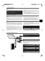 3
3
-
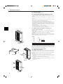 4
4
-
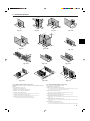 5
5
-
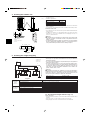 6
6
-
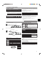 7
7
-
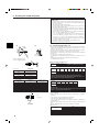 8
8
-
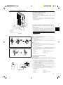 9
9
-
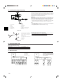 10
10
-
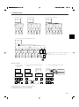 11
11
-
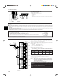 12
12
-
 13
13
-
 14
14
-
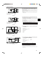 15
15
-
 16
16
-
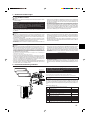 17
17
-
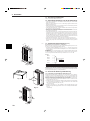 18
18
-
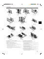 19
19
-
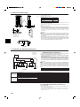 20
20
-
 21
21
-
 22
22
-
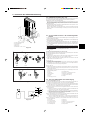 23
23
-
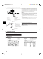 24
24
-
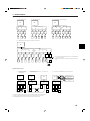 25
25
-
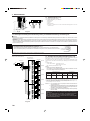 26
26
-
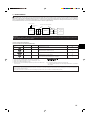 27
27
-
 28
28
-
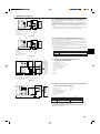 29
29
-
 30
30
-
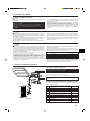 31
31
-
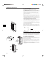 32
32
-
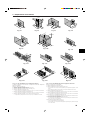 33
33
-
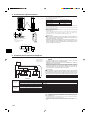 34
34
-
 35
35
-
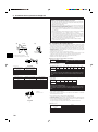 36
36
-
 37
37
-
 38
38
-
 39
39
-
 40
40
-
 41
41
-
 42
42
-
 43
43
-
 44
44
-
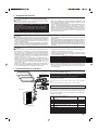 45
45
-
 46
46
-
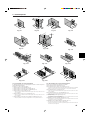 47
47
-
 48
48
-
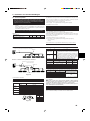 49
49
-
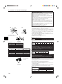 50
50
-
 51
51
-
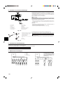 52
52
-
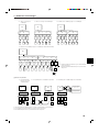 53
53
-
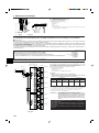 54
54
-
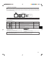 55
55
-
 56
56
-
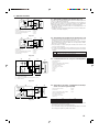 57
57
-
 58
58
-
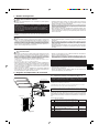 59
59
-
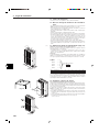 60
60
-
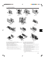 61
61
-
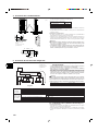 62
62
-
 63
63
-
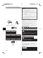 64
64
-
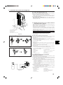 65
65
-
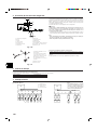 66
66
-
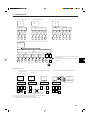 67
67
-
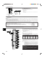 68
68
-
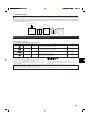 69
69
-
 70
70
-
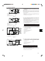 71
71
-
 72
72
-
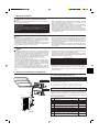 73
73
-
 74
74
-
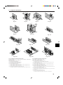 75
75
-
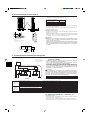 76
76
-
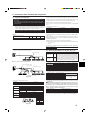 77
77
-
 78
78
-
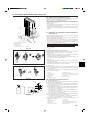 79
79
-
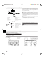 80
80
-
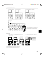 81
81
-
 82
82
-
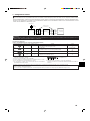 83
83
-
 84
84
-
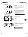 85
85
-
 86
86
-
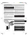 87
87
-
 88
88
-
 89
89
-
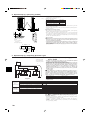 90
90
-
 91
91
-
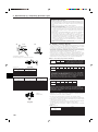 92
92
-
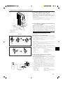 93
93
-
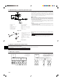 94
94
-
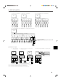 95
95
-
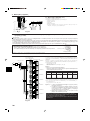 96
96
-
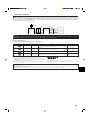 97
97
-
 98
98
-
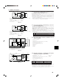 99
99
-
 100
100
-
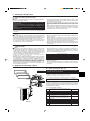 101
101
-
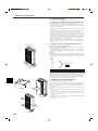 102
102
-
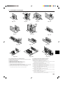 103
103
-
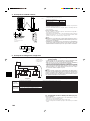 104
104
-
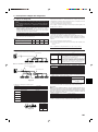 105
105
-
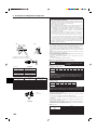 106
106
-
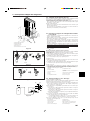 107
107
-
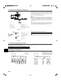 108
108
-
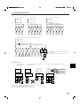 109
109
-
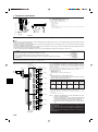 110
110
-
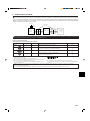 111
111
-
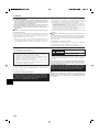 112
112
-
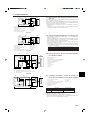 113
113
-
 114
114
-
 115
115
-
 116
116
-
 117
117
-
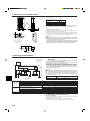 118
118
-
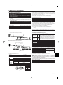 119
119
-
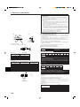 120
120
-
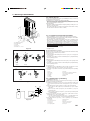 121
121
-
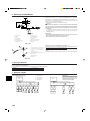 122
122
-
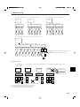 123
123
-
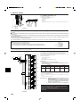 124
124
-
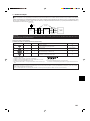 125
125
-
 126
126
-
 127
127
-
 128
128
-
 129
129
-
 130
130
-
 131
131
-
 132
132
-
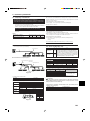 133
133
-
 134
134
-
 135
135
-
 136
136
-
 137
137
-
 138
138
-
 139
139
-
 140
140
-
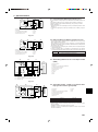 141
141
-
 142
142
-
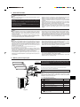 143
143
-
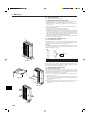 144
144
-
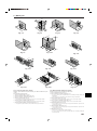 145
145
-
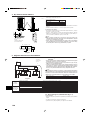 146
146
-
 147
147
-
 148
148
-
 149
149
-
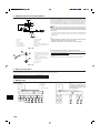 150
150
-
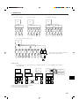 151
151
-
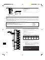 152
152
-
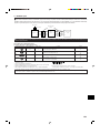 153
153
-
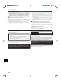 154
154
-
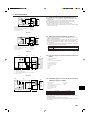 155
155
-
 156
156
-
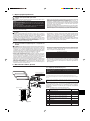 157
157
-
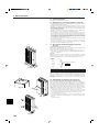 158
158
-
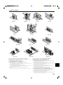 159
159
-
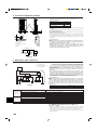 160
160
-
 161
161
-
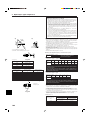 162
162
-
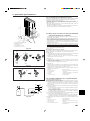 163
163
-
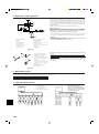 164
164
-
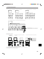 165
165
-
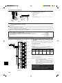 166
166
-
 167
167
-
 168
168
-
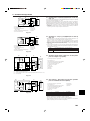 169
169
-
 170
170
-
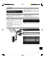 171
171
-
 172
172
-
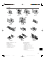 173
173
-
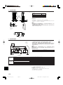 174
174
-
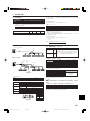 175
175
-
 176
176
-
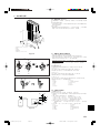 177
177
-
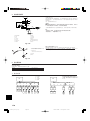 178
178
-
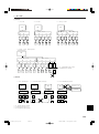 179
179
-
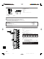 180
180
-
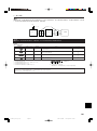 181
181
-
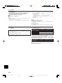 182
182
-
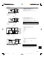 183
183
-
 184
184
-
 185
185
-
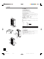 186
186
-
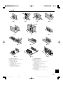 187
187
-
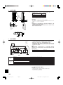 188
188
-
 189
189
-
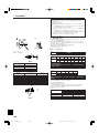 190
190
-
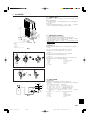 191
191
-
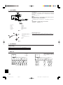 192
192
-
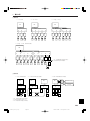 193
193
-
 194
194
-
 195
195
-
 196
196
-
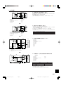 197
197
-
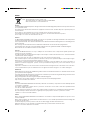 198
198
-
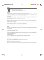 199
199
-
 200
200


Mitsubishi MSZ-DM35VA Bedienungsanleitung
- Kategorie
- Split-System-Klimaanlagen
- Typ
- Bedienungsanleitung
- Dieses Handbuch eignet sich auch für
in anderen Sprachen
- English: Mitsubishi MSZ-DM35VA Owner's manual
- français: Mitsubishi MSZ-DM35VA Le manuel du propriétaire
- español: Mitsubishi MSZ-DM35VA El manual del propietario
- italiano: Mitsubishi MSZ-DM35VA Manuale del proprietario
- русский: Mitsubishi MSZ-DM35VA Инструкция по применению
- Nederlands: Mitsubishi MSZ-DM35VA de handleiding
- português: Mitsubishi MSZ-DM35VA Manual do proprietário
- dansk: Mitsubishi MSZ-DM35VA Brugervejledning
- svenska: Mitsubishi MSZ-DM35VA Bruksanvisning
- Türkçe: Mitsubishi MSZ-DM35VA El kitabı
Verwandte Artikel
Andere Dokumente
-
Mitsubishi Electric PUMY-P125 Installationsanleitung
-
Chariot Carriers Merci Installationsanleitung
-
-
Airwell 60K Installation Instructions Manual
-
mundoclima Serie MUCSR-H8 “Cassette Super Inverter H8” Bedienungsanleitung
-
Haier 1U48IS1EAB Installationsanleitung
-
Hitachi RAC-50WPC Installationsanleitung
-
-
-