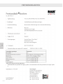
RAIS attika VISIO Series Installationsanleitung
- Kategorie
- Kamine
- Typ
- Installationsanleitung

VISIO GAS
INSTALLATION GUIDE
INSTALLATIONSANLEITUNG
INSTALLATIONSVEJLEDNING
INSTALLASJONSVEILEDNING
INSTALLATIONSANVISNING


INSTALLATION MANUAL
INSTALLATION MANUALGB
We are not responsible for typographical errors.
CONTENTS
Introduction ................................................................................................................................................... 3
Certication ................................................................................................................................................... 4
Your new gas replace in general .................................................................................................................. 5
Before installation .................................................................................................................................. 5
Gas connection ..................................................................................................................................... 5
Safety ............................................................................................................................................................. 6
Gas supply emergency stop .................................................................................................................. 6
Delivery packaging ........................................................................................................................................ 7
Overview of contents .................................................................................................................................... 8
Information plate ................................................................................................................................... 8
Removing the glass ....................................................................................................................................... 9
Fitting the burner ........................................................................................................................................ 12
Flue system .................................................................................................................................................. 15
Positioning ue terminals ............................................................................................................................ 16
Horizontal wall terminal, type C11 .............................................................................................................. 17
Vertical roof terminal, type C31 ................................................................................................................... 18
Pipework .............................................................................................................................................. 18
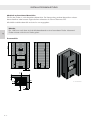
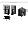
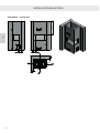
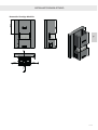
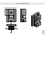
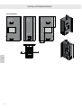
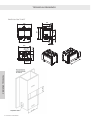
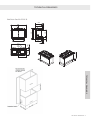
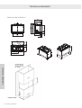
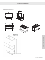
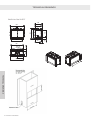
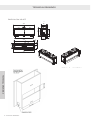
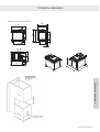
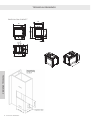
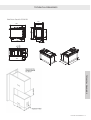
Installation of replace ................................................................................................................................ 19
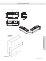
Installation dimensions ........................................................................................................................ 19
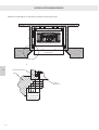
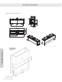
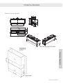
Distance between combustible material ............................................................................................. 20
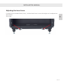
Adjusting the base frame ........................................................................................................................... 27
Fitting secondary burners ............................................................................................................................ 28
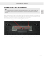
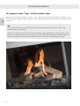
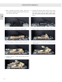
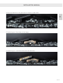
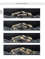
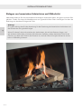
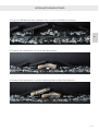
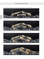
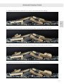
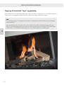
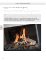
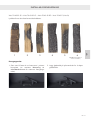
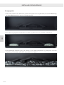
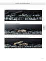
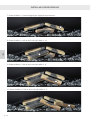
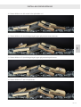
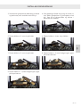
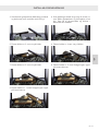
Arranging ceramic “logs” and embers layer ............................................................................................... 29
Arranging ceramic “logs” and the embers layer ......................................................................................... 30
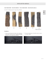
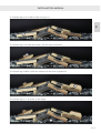
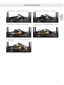
Visio 70-43-39 3S – Visio 70-43-39 LC – Visio 70-43-39 RC – Visio 70-43 F (Visio 3) .......................... 31
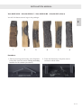
Visio 90-55-39 3S – Visio 90-55-39 LC – Visio 90-55-39 RC – Visio 90-55 F (Visio 4) .......................... 33
Visio 160-45-32 3S – Visio 160-45-32 LC – Visio 160-45-32 RC – Visio 160-45 F (Visio 5) .................. 35
Visio 43-49-65 RD – Visio 43-49-65 T (Visio 6) .................................................................................... 40
Visio 40-55-90 RD – Visio 40-55-90 T (Visio 7) .................................................................................... 42
Fitting the frame .......................................................................................................................................... 44
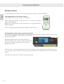
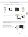
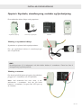
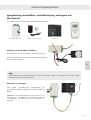
Start-up: Control box, power supply, receiver and remote control ............................................................. 45
Connection of control box for LED light ............................................................................................ 45
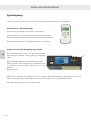
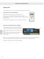
Remote control ............................................................................................................................................ 46
Inserting batteries in the remote control ............................................................................................. 46
Synchronisation of the remote control and receiver ........................................................................... 46
GB - 2
GB

INSTALLATION MANUAL
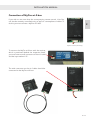
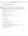
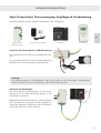
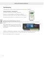
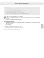
Connection of MyFire wi--box ................................................................................................................... 47
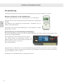
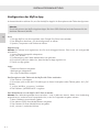
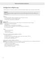
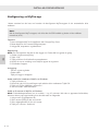
Conguration of the MyFire app ................................................................................................................. 48
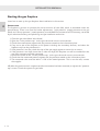
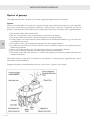
Starting the gas replace............................................................................................................................. 50
Pressure test ........................................................................................................................................ 50
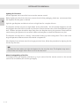
Functional test when lighting the re for the rst time ....................................................................... 51
Lighting for rst time ........................................................................................................................... 52
Manual extinguishing of the re .......................................................................................................... 52
Service and maintenance ............................................................................................................................ 53
Service procedure ............................................................................................................................... 53
Warranty ...................................................................................................................................................... 55
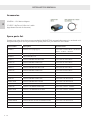
Accessories .................................................................................................................................................. 56
Spare parts list ............................................................................................................................................ 56
Technical information ................................................................................................................................. 58
Technical data .............................................................................................................................................. 60
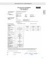
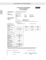
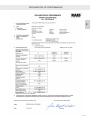
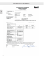
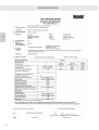
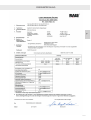
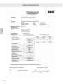
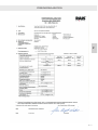
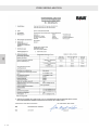
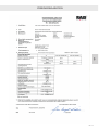
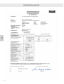
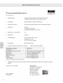
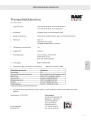
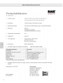
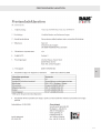
Performance declaration ............................................................................................................................. 70
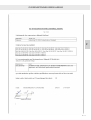
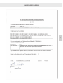
Declaration of conformity ............................................................................................................................ 75
Troubleshooting .......................................................................................................................................... 77
Dimensional drawings and installation drawings ........................................................................................ 78
RAIS Visio Gas 70-43-39 3S ................................................................................................................. 78
RAIS Visio Gas 70-43-39 LC ................................................................................................................ 79
RAIS Visio Gas 70-43-39 RC ................................................................................................................ 80
RAIS Visio Gas 70-43 F ........................................................................................................................ 81
RAIS Visio Gas 90-55-39 3S ................................................................................................................. 82
RAIS Visio Gas 90-55-39 LC ................................................................................................................ 83
RAIS Visio Gas 90-55-39 RC ................................................................................................................ 84
RAIS Visio Gas 90-55 F ........................................................................................................................ 85
RAIS Visio Gas 160-45-32 3S ............................................................................................................... 86
RAIS Visio Gas 160-45-32 LC .............................................................................................................. 87
RAIS Visio Gas 160-45-32 RC .............................................................................................................. 88
RAIS Visio Gas 160-45 F ...................................................................................................................... 89
RAIS Visio Gas 43-49-65 RD ................................................................................................................ 90
RAIS Visio Gas 43-49-65 T ................................................................................................................... 91
RAIS Visio Gas 40-55-90 RD ................................................................................................................ 92
RAIS Visio Gas 40-55-90 T ................................................................................................................... 93
Examples of extraction solutions ................................................................................................................. 94
Extraction parts............................................................................................................................................ 99
Information plate ....................................................................................................................................... 103
3 - GB
GB

INSTALLATION MANUAL
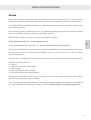
Introduction
Congratulations on the acquisition of your new gas replace and on becoming a RAIS or ATTIKA
customer!
You have chosen a gas replace where quality, design and function go hand-in-hand.
Follow us on all of our digital platforms to get the latest tips, know-how and inspiration.
We have put all of our expertise, experience and passion into every single product – in other words,
focused all of our efforts into ensuring that you acquire a gas replace that will bring you happiness
for many years to come. Now you can get to know your gas replace and realise your dream and our
dream – that you can have a wonderful and comforting gas replace in your home. Please therefore
read these instructions carefully so that you get the most out of your new gas replace.
To begin with, nd the gas replace production number on the top left corner of the replace and
write it down in the text box:
The number is the replace’s identication number and must be used when making any enquiries
relating to the replace’s warranty.
Date:
Dealer:
GB - 4
GB

INSTALLATION MANUAL
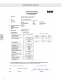
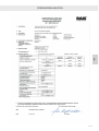
Certification
This gas replace is tested and certied for use in several countries (see the information plate on the
back of the installation manual). The gas replace has been tested for use with natural gas, town gas,
LPG and biogas.
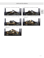
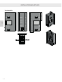
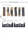
This installation manual covers the following models:
(VISIO 3)
Visio Gas 70-43-39 3S – three sides
Visio Gas 70-43-39 LC – Left Corner unit
Visio Gas 70-43-39 RC – Right Corner unit
Visio Gas 70-43 F – Front unit
(VISIO 4)
Visio Gas 90-55-39 3S – three sides
Visio Gas 90-55-39 LC – Left Corner unit
Visio Gas 90-55-39 RC – Right Corner unit
Visio Gas 90-55 F – Front unit
(VISIO 5)
Visio Gas 160-45-32 3S – three sides
Visio Gas 160-45-32 LC – Left Corner unit
Visio Gas 160-45-32 RC – Right Corner unit
Visio Gas 160-45 F – Front unit
(VISIO 6)
Visio Gas 43-49-65 RD – Room Divider, three sides
Visio Gas 43-49-65 T – Tunnel
(VISIO 7)
Visio Gas 40-55-90 RD – Room Divider, three sides
Visio Gas 40-55-90 T – Tunnel
NB:
You will nd the information plate for your replace’s model number placed on top of the gas
replace on delivery.
Tested by:
Intertek Testing & Certication Ltd,
Registered ofce: Academy Place, 1 to 9 Brook Street, Brentwood, Essex
CM14 5NQ, United Kingdom Registered No: 3272281
(England), VAT No: GB 672-7639-96-011
Tel.: +44 1277 223 400
Fax: +44 1277 223 127
5 - GB
GB

INSTALLATION MANUAL
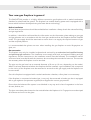
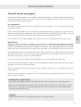
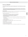
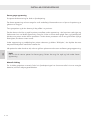
Your new gas fireplace in general
This RAIS/ATTIKA product is a highly efcient convection gas replace with a sealed combustion
chamber for a balanced ue system. The replace has variable heating power and is equipped with a
burner which has been developed using the latest burner technology.
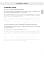
Before installation
All local laws and provisions should be studied before installation. Always check the national building
and gas regulations.
In addition, it should be conrmed that the information on the information plate relating to gas type
and gas pressure are in accordance with the local gas conditions that the replace shall be installed
under. The gas supply should be examined to ensure that it can supply the required amount of gas
and the required pressure.
It is recommended that gloves are worn when installing the gas replace to avoid ngerprints on
glass, etc.
Gas connection
This replace may only be installed, adjusted and serviced by an authorised and qualied heating
and plumbing/gas technician. The installation must comply with local and national building and gas
regulations, and the instructions in the installation manual must be followed. The installation manual
and user manual must be left with the customer, who must keep the manuals for later use. The manuals
are necessary when the replace is to be serviced.
The pipe on the gas hose has an external diameter of 8 mm or 10 mm, depending on the model.
When it has been determined where the replace shall be installed, a gas installation with a stopcock
in the vicinity of the replace must be executed to ensure that the gas supply and the replace can
be connected.
Since this replace is equipped with a sealed combustion chamber, a oor plate is not necessary.
If the replace is connected to bottled gas, it may only be connected to bottle gas that is equipped
with a gas regulator (low pressure regulator) that supplies the correct gas pressure.
Ensure that the balanced ue system is not blocked in any way and is free of vegetation in the form
of trees, bushes, etc.
The glass must always be cleaned on the outside before the replace is lit. Fingerprints must be wiped
off as these can burn into the glass.
GB - 6
GB

INSTALLATION MANUAL
Gas supply emergency stop
If you smell gas, immediately switch off the gas supply. Turn off the replace at the stopcock and
main switch.
Ventilate the room by opening windows and doors. Do not use electrical appliances or switches in
the vicinity of the replace. The gas supply may not be reconnected until an authorised heating
and plumbing/gas technician has examined the replace and approved it.
NB!
RAIS/ATTIKA recommends 20 mm gas supply pipes for town gas burners.
Safety
It is important that the replace is correctly installed in consideration of the environment and people’s
safety. No unauthorised alterations may be made to the replace.
The replace may not be used if the glass is split, cracked or removed. Do not use the replace if the
glass gasket is broken or worn.
This replace is designed for use in many different installation situations, which are shown in this
manual. Only ue systems that are CE approved for this product may be used (see the section “ue
system”).
This replace is designed for a balanced ue system (air intake and extraction in the same chimney).
Therefore there is no need for an extra air supply for combustion. It is recommended that the air
replacement in the room is adjusted to ensure a pleasant indoor environment. This replace can be
installed in an airtight building or in a building with mechanical ventilation, since the gas replace
functions in a closed system that does not extract combustion air from the room.
NB!
The replace must be installed in reproofed material. Due to the risk of re, ammable items
(e.g. furniture) may not be positioned closer than 500 mm from the front of the glass.
This product is a heating appliance. This means that surfaces become very hot and must not be
touched when the replace is in use. It is therefore recommended that an approved screen is
used to protect children, seniors and persons with limited mobility who are in the vicinity of the
replace.
If the replace is switched off or the re goes out, wait at least three minutes before lighting it
again.
7 - GB
GB

INSTALLATION MANUAL
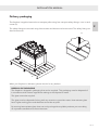
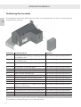
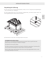
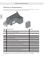
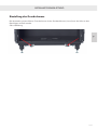
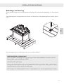
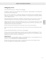
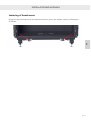
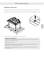
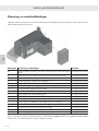
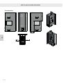
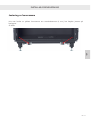
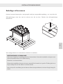
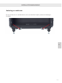
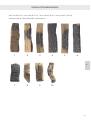
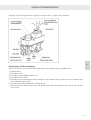
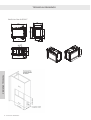
Delivery packaging
The replace is supplied secured to a transport pallet using four transport safety ttings – one in each
corner (A).
The safety ttings are secured using three screws and these must be removed. The safety tting can
then be removed.
When your replace is delivered, please check it for any defects.
A
A
Material:
Remarks:
Bend Tool:
Established:
Designer: Project manager:
Format:
Approved:
Drawing no.:Revision:Project:
Drawing name:
INDUSTRIVEJ 20, 9900 FREDERIKSHAVN, DENMARK
Phone +45 98 47 90 33 - Fax +45 98 47 92 91
E-mail: info@rais.dk - Homepage: www.rais.dk
Change order
Drawing change: Improvement proposal:
Corrections:
D M Y
PCH
21-12-2018
A3
3248601
1.8
6-30
0-10
0.2
1°
1000-2000
0.15
0.3
1.2
0-5°
> 400
TILLADTE AFVIGELSER FOR VINKELMÅL
50-120
120-400
0-10°
0.8
400-1000
0.5
120-400
0-20°
0-30°
0.3
10-50
30-120
0.9
0.6
3-6
TILLADTE AFVIGELSER FOR LINIEÆRE MÅL
AFVIGELSE I MM
0.1
0.1
VINKELAFVIGELSE
KORTESTE SIDE
0.5-3
pr. 100 mm
OV UV
DISPOSAL OF PACKAGING
The replace is shipped in packaging that can be recycled. This packaging must be disposed of
in accordance with national regulations relating to the disposal of waste.
The glass cannot be recycled.
The glass must be disposed of along with any ceramics or porcelain waste. Heat-resistant glass
has a higher melting point and therefore cannot be recycled.
By ensuring heat-resistant glass does not end up alongside recyclable products you are making
an important contribution to the environment.
GB - 8
GB

INSTALLATION MANUAL
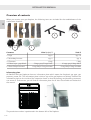
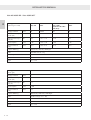
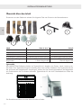
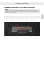
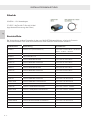
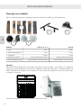
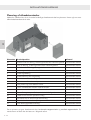
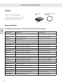
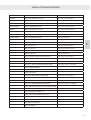
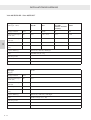
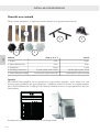
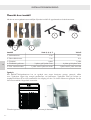
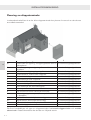
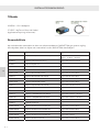
Overview of contents
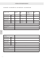
When you receive your gas replace, the following items are included for the establishment of the
combustion chamber:
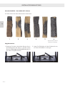
Contents Visio 3, 4, 6, 7 Visio 5
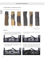
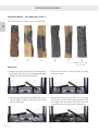
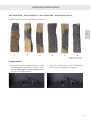
1. Logs qty. 6 qty. 10
2. Secondary burners qty. 2 qty. 4
3. Filaments 1 bag 1 bag
4. Ember layer: grey/black 3 bags grey/3 bags black 4 bags grey/4 bags black
5. Glass: Sharp/rounded 1 bag sharp/1 bag rounded 1 bag sharp/1 bag rounded
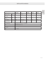
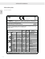
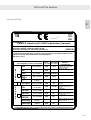
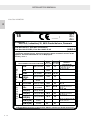
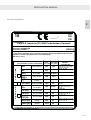
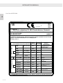
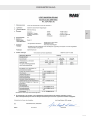
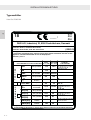
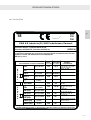
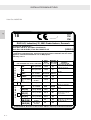
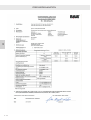
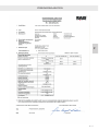
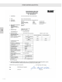
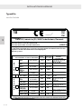
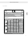
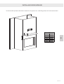
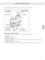
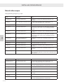
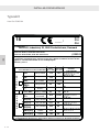
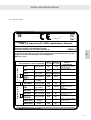
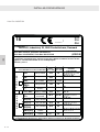
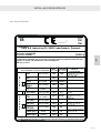
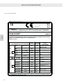
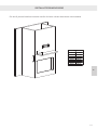
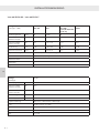
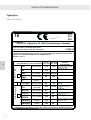
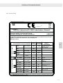
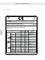
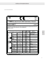
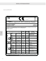
Information plate
All RAIS/ATTIKA gas replaces have an information plate which states the replace’s gas type, gas
pressure, power, etc. The information plate is laid on top of the gas replace on delivery. Position the
information plate on the inside of the inspection hatch so that the heating and plumbing contractor
can access it. Furthermore, you will nd an information plate for all Visio Gas models on the back of
the manual.
The production number is positioned in the bottom left of the replace.
1
2 3
4 5
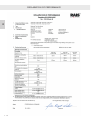
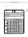
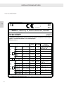
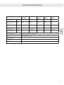
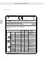
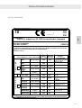
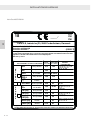
Product ID: 0359CS1717
Produced at:
RAIS A/S, Industrivej 20, 9900 Frederikshavn, Danmark
Hergestellt für /Produced for:
ATTIKA FEUER AG, Brunnmatt 16, CH-6330 Cham / RAIS A/S, Industrivej 20, DK-9900 Frederikshavn
CE Label: Rev. 2_27-09-2019
Visio Gas 70/43/XX
(VISIO 3)
18
C11
C31
C91
____ /
This appliance must be installed in accordance with the rules in force, and only used in
a sufficiently ventilated space. Consult instructions before installation and use of this
appliance. Tested and Certified for use on Biopropane.
Efficiency class 1
N
A
T
U
R
A
L
P
R
O
P
A
N
E
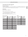
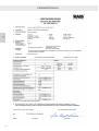
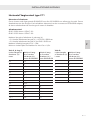
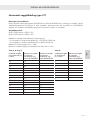
GAS CATEGORY and SUPPLY PRESSURE
I2H
I2E
I2E+
I2ELL
I2L I2EK
I2 (43.46 -45.3 MJ/m3
(0°C))
I3+
I3P(30)
I3P(37)
I3P(50)
I3B/P(30)
I3B/P(50)
HEAT
INPUT
(Gross, KW)
BURNER
PRESSURE
(Hot, mbar)
COUNTRY
of DESTINATION
G20 @ 20 mbar
G20 @ 20 mbar
G20↔G25 @
20↔25 mbar
G25 @ 20 mbar
G20/G25.3 @
25 mbar
G30↔G31 @
28↔37 mbar
G31 @ 30 mbar
G31 @ 37 mbar
G31 @ 50 mbar
G30↔G31 @
30 mbar
G30↔G31 @
50 mbar
11.5
11.5
11.5/10.6
9.8
10.6
10.5
9.5
10.5
10.5
10.5
10.5
36
27
36
36
28
27/36
22.1
18.0
18.5/22
18.5
18.5
AT, BG, CH, CZ, DK, EE, ES, FI,
GB, GR, HR, IE, IT, LT, LV, NO,
PT, RO, SE, SI, SK, TR
DE, LU, PL, RO
BE, FR
DE
NL
BE, CH, CY, CZ, ES, FR,
GB, GR, IE, IT, LT, PT, SI,
SK, TR
FI, NL, RO
BE, CH, CZ, ES, FR, GB,
GR, HR, IE, IT, LT, NL, PL,
PT, SL, SK, TR
AT, CH, CZ, DE, NL, SK
BE, BG, CY, DK, EE, FI, FR, GB,
GR, HR, HU, IT, LT, MT, NL, NO,
RO, SE, SI, SK, TR
AT, CH, CZ, DE, FR, SK
Visio Gas 70/43 F, Visio Gas 70/43/39 LC,
Visio Gas 70/43/39 RC, Visio Gas 70/43/39 3S
CITY GAS
G150.1 @ 8 mbar
9.4
3.5
DK, SE
(VISIO 3)
9 - GB
GB

INSTALLATION MANUAL
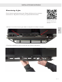
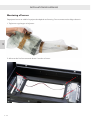
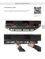
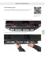
Scan the QR code to see
a video of how to remove
the glass.
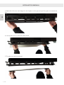
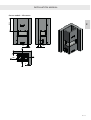
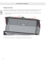
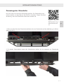
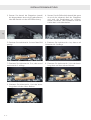
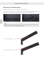
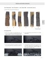
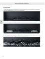
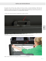
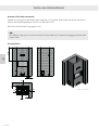
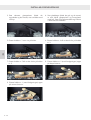
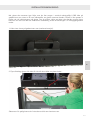
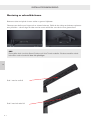
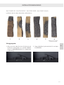
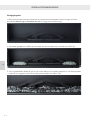
Removing the glass
The replace is supplied with the glass tted. The glass must be removed in
order to t the replace burner. Follow these instructions when the glass has
to be removed.
1. There is a rotary disc at the top of each side of the replace glass (as shown with arrow).
2. Turn the two rotary discs anticlockwise until they are horizontal with the glass.
GB - 10
GB

INSTALLATION MANUAL
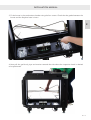
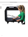
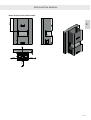
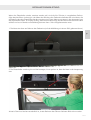
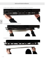
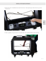
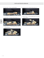
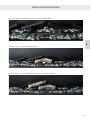
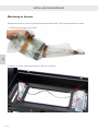
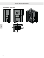
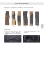
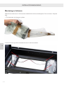
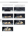
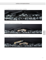
3. Take hold of the two metal edges for the replace on the glass and pull the glass out towards the
front.
4. Lift the glass until it is free of the base frame.
5. The glass can now be removed.
11 - GB
GB

INSTALLATION MANUAL
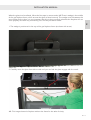
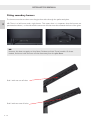
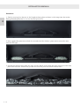
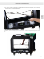
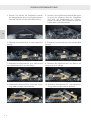
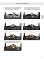
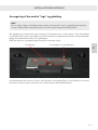
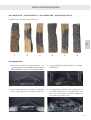
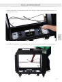
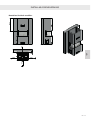
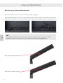
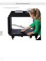
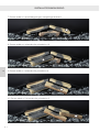
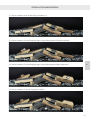
When the glass is to be retted, follow the ve steps in reverse order. NB! There is wedge in the middle
of the gas replace frame, which ensures the glass is tted correctly. This wedge must t between the
two notches on the glass. It is very important that this is done correctly otherwise the replace will not
close properly and soot may form during use. See the procedure below.
1. The wedge is positioned in the top of the gas replace frame (as shown with arrow).
2. Carefully move the glass from side to side until you can feel the glass engage with the notch.
NB: This image shows the replace without the frame for the sake of clarity.
GB - 12
GB

INSTALLATION MANUAL
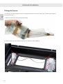
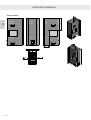
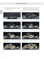
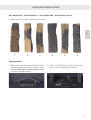
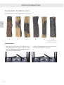
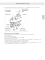
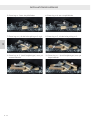
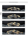
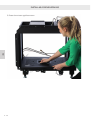
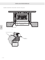
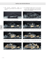
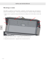
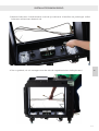
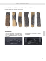
Fitting the burner
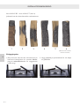
On delivery, the gas replace burner is supplied separated from the base plate. Follow these steps to
t the gas burner.
1. Remove the burner and hose from the bag.
2. Remove the four front-tted screws on the bottom of the replace.
13 - GB
GB

INSTALLATION MANUAL
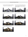
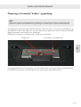
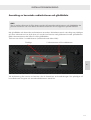
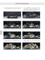
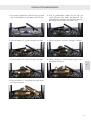
3. Fit the burner in the combustion chamber using the four screws. Check that the gasket between the
burner and the replace base is intact.
4. Now pull the gas block, pipe and receiver towards the side where the inspection hatch is desired
to be positioned.
GB - 14
GB

INSTALLATION MANUAL
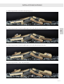
5. Position the bottom grate above the burner.
15 - GB
GB

INSTALLATION MANUAL
Flue system
This replace may be installed with either a roof terminal (C31) or a wall terminal (C11). The replace
may only be installed using a balanced ue (also known as concentric ue system) in the way stated
by RAIS/ATTIKA.
The ue pipes recommended by RAIS/ATTIKA have been approved together with the replace and
the replace may only be installed when using these.
If national legislation allows it, a CE approved ue ventilator can be used with all Visio Gas models.
Study the national legislation for this area.
RAIS/ATTIKA recommends that the replace is tted using a ue of the brand:
OnTop Metaloterm USD or OnTop Metaloterm US.
Other approved ue system manufacturers are: Jeremias, Muelink & Grol and Poujoulat PGI.
The joints on the ue pipes must be sealed and secured against separation using hose clips or screws.
A measuring nozzle must be tted on the ue in the same room as the replace in order to carry out
combustion checks.
It must be ensured that the ue terminal’s position is in accordance with national building regulations.
The ue outlet must not end:
• In a carport
• In a light shaft, niche or cellerway
• Under stairs
• Under an extension or similar
• Facing a walkway or public area
The ue system is what makes the replace function. The replace will not function optimally if it does
not have the correct and necessary ow in the ue system.
The replace is supplied with a spigot prepared for the interior tting of a ue pipe with a diameter
of 100/150 mm and 130/200 mm, depending on the model – see section Dimensional drawings and
installation drawings.
GB - 16
GB

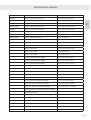
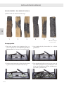
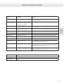
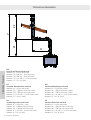
INSTALLATION MANUAL
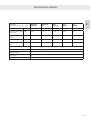
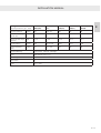
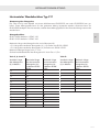
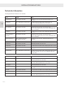
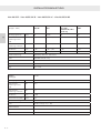
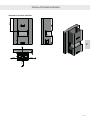
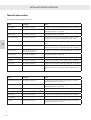
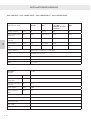
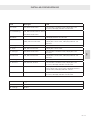
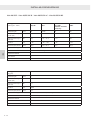
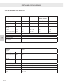
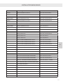
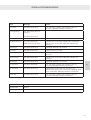
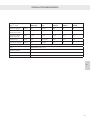
Dimension Terminal position Distance
A* Directly below an opening, an opening window
or ventilation duct.
See national regulatory requirements.
B Directly above an opening, an opening window
or ventilation duct.
See national regulatory requirements.
C At the side of an opening, an opening window,
etc.
See national regulatory requirements.
D Below gutters or drainage pipes. See national regulatory requirements.
E Below eaves. See national regulatory requirements.
R Below balconies or carport roofs. See national regulatory requirements.
G From a vertical drainage pipe. See national regulatory requirements.
H From an internal or external corner. See national regulatory requirements.
I Above the ground - roof or balcony level. See national regulatory requirements.
J From a surface that faces towards the terminal. See national regulatory requirements.
K From a terminal that faces towards the terminal. See national regulatory requirements.
L From an opening in a carport (e.g. door,
window into the home).
See national regulatory requirements.
M Vertically from a terminal on the same wall. See national regulatory requirements.
N Horizontally from a terminal on the same wall. See national regulatory requirements.
P From a vertical structure on the roof. See national regulatory requirements.
Q Above the intersection point with the roof. See national regulatory requirements.
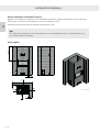
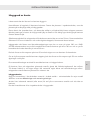
There are primarily two types of ue terminals: Horizontal wall terminals and vertical roof terminals.
The dimensions of these are given in the following section.
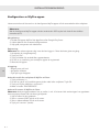
Positioning flue terminals
The table below shows how different ue terminals can be positioned in the house and how large the
safety distances must be.
17 - GB
GB

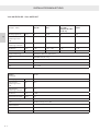
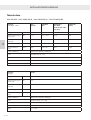
INSTALLATION MANUAL
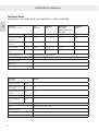
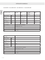
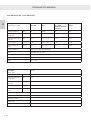
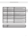
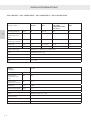
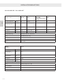
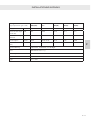
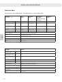
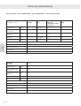
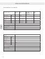
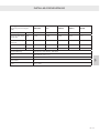
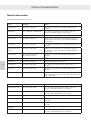
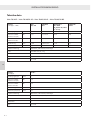
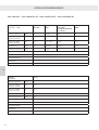
Vertical length
of ue pipe (V) in
metres
Maximum length
of horizontal ue
pipe (H) in metres
Ø130/Ø200
Maximum length
of horizontal ue
pipe (H) in metres
Ø100/Ø150
0.5 1.5 1
1 3 2
1.5 4.5 3
2 6 4
2.5 7.5 5
3 9 6
3.5 10.5 7
4 11 8
4.5 10.5 9
5 10 10
5.5 9.5 9.5
6.5 8.5 8.5
7 8 8
7.5 < 7.5 7.5
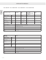
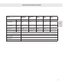
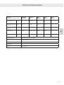
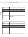
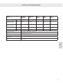
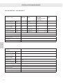
Vertical length
of ue pipe (V)
in metres
Maximum length
of horizontal ue
pipe (H) in metres
Ø130/Ø200
1 2
2 4
3 6
4 8
5 10
6 9
7 8
8 7
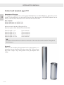
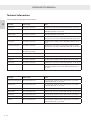
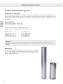
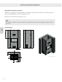
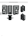
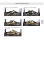
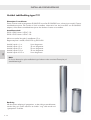
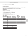
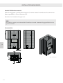
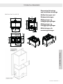
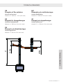
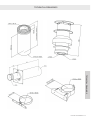
Horizontal wall terminal, type C11
Dimensions of ue pipe:
The replace is supplied with an outlet spigot Ø100/Ø150 mm or Ø130/Ø200 mm, depending on the
model. This ue dimension can be used for the entire ue. Alternatively, a Ø130/Ø200 adapter can be
tted, so that this ue dimension can be used for the rest of the ue.
Flue terminal:
Ø130 / Ø200 Item no. USDHC 130
Ø100 / Ø150 Item no. USDHC 100
Maximum length of ue pipe to outer wall (H)
= 3 X vertical ue pipe length (V) -1 for Ø130 / Ø200 pipe.
= 2 X vertical ue pipe length (V) for Ø100 / Ø150 pipe.
Maximum permitted length (V + H) = 15 m.
Minimum vertical height of ue pipe for Visio Gas = 0.5 m.
Visio 5:Visio 3, 4, 6 and 7:
GB - 18
GB

INSTALLATION MANUAL
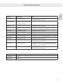
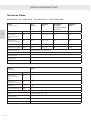
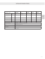
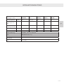
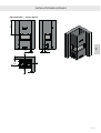
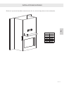
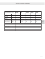
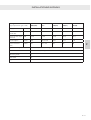
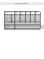
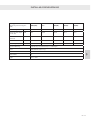
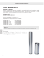
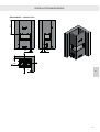
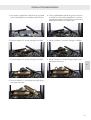
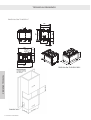
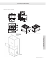
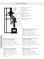
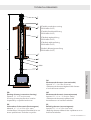
Vertical roof terminal, type C31
Dimensions of ue pipe:
The replace is supplied with an outlet spigot Ø100/Ø150 mm or Ø130/Ø200 mm, depending on the
model. This ue dimension can be used for the entire ue. Alternatively, a Ø130/Ø200 adapter can be
tted, so that this ue dimension can be used for the rest of the ue.
Flue terminal:
Ø130 / Ø200 Item no. USDVC 130
Ø100 / Ø150 Item no. USDVC 100
Minimum vertical length of ue pipe 0.5 m.
Restrictor plate in ue, Ø100/150 and Ø130/200
Vertical height < 1 m 0 mm restrictor
Vertical height 1–2 m 35 mm restrictor
Vertical height 2–5 m 50 mm restrictor
Vertical height 5–10 m 35 mm restrictor
Vertical height 10–15 m 0 mm restrictor
NB:
Examples of ue solutions are shown at the back of the manual under the section ‘Examples of
ue solutions’.
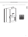
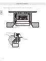
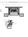
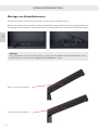
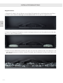
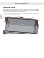
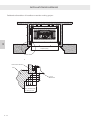
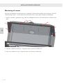
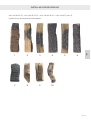
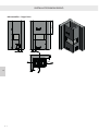
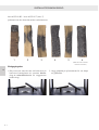
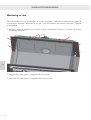
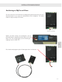
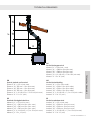
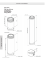
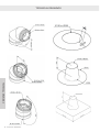
Pipework
When you start installing the pipework for the gas replace, it is
important that the ue pipe faces the correct way. The end must
only have a single “ring” facing down in the gas replace. See
image.
19 - GB
GB
Seite laden ...
Seite laden ...
Seite laden ...
Seite laden ...
Seite laden ...
Seite laden ...
Seite laden ...
Seite laden ...
Seite laden ...
Seite laden ...
Seite laden ...
Seite laden ...
Seite laden ...
Seite laden ...
Seite laden ...
Seite laden ...
Seite laden ...
Seite laden ...
Seite laden ...
Seite laden ...
Seite laden ...
Seite laden ...
Seite laden ...
Seite laden ...
Seite laden ...
Seite laden ...
Seite laden ...
Seite laden ...
Seite laden ...
Seite laden ...
Seite laden ...
Seite laden ...
Seite laden ...
Seite laden ...
Seite laden ...
Seite laden ...
Seite laden ...
Seite laden ...
Seite laden ...
Seite laden ...
Seite laden ...
Seite laden ...
Seite laden ...
Seite laden ...
Seite laden ...
Seite laden ...
Seite laden ...
Seite laden ...
Seite laden ...
Seite laden ...
Seite laden ...
Seite laden ...
Seite laden ...
Seite laden ...
Seite laden ...
Seite laden ...
Seite laden ...
Seite laden ...
Seite laden ...
Seite laden ...
Seite laden ...
Seite laden ...
Seite laden ...
Seite laden ...
Seite laden ...
Seite laden ...
Seite laden ...
Seite laden ...
Seite laden ...
Seite laden ...
Seite laden ...
Seite laden ...
Seite laden ...
Seite laden ...
Seite laden ...
Seite laden ...
Seite laden ...
Seite laden ...
Seite laden ...
Seite laden ...
Seite laden ...
Seite laden ...
Seite laden ...
Seite laden ...
Seite laden ...
Seite laden ...
Seite laden ...
Seite laden ...
Seite laden ...
Seite laden ...
Seite laden ...
Seite laden ...
Seite laden ...
Seite laden ...
Seite laden ...
Seite laden ...
Seite laden ...
Seite laden ...
Seite laden ...
Seite laden ...
Seite laden ...
Seite laden ...
Seite laden ...
Seite laden ...
Seite laden ...
Seite laden ...
Seite laden ...
Seite laden ...
Seite laden ...
Seite laden ...
Seite laden ...
Seite laden ...
Seite laden ...
Seite laden ...
Seite laden ...
Seite laden ...
Seite laden ...
Seite laden ...
Seite laden ...
Seite laden ...
Seite laden ...
Seite laden ...
Seite laden ...
Seite laden ...
Seite laden ...
Seite laden ...
Seite laden ...
Seite laden ...
Seite laden ...
Seite laden ...
Seite laden ...
Seite laden ...
Seite laden ...
Seite laden ...
Seite laden ...
Seite laden ...
Seite laden ...
Seite laden ...
Seite laden ...
Seite laden ...
Seite laden ...
Seite laden ...
Seite laden ...
Seite laden ...
Seite laden ...
Seite laden ...
Seite laden ...
Seite laden ...
Seite laden ...
Seite laden ...
Seite laden ...
Seite laden ...
Seite laden ...
Seite laden ...
Seite laden ...
Seite laden ...
Seite laden ...
Seite laden ...
Seite laden ...
Seite laden ...
Seite laden ...
Seite laden ...
Seite laden ...
Seite laden ...
Seite laden ...
Seite laden ...
Seite laden ...
Seite laden ...
Seite laden ...
Seite laden ...
Seite laden ...
Seite laden ...
Seite laden ...
Seite laden ...
Seite laden ...
Seite laden ...
Seite laden ...
Seite laden ...
Seite laden ...
Seite laden ...
Seite laden ...
Seite laden ...
Seite laden ...
Seite laden ...
Seite laden ...
Seite laden ...
Seite laden ...
Seite laden ...
Seite laden ...
Seite laden ...
Seite laden ...
Seite laden ...
Seite laden ...
Seite laden ...
Seite laden ...
Seite laden ...
Seite laden ...
Seite laden ...
Seite laden ...
Seite laden ...
Seite laden ...
Seite laden ...
Seite laden ...
Seite laden ...
Seite laden ...
Seite laden ...
Seite laden ...
Seite laden ...
Seite laden ...
Seite laden ...
Seite laden ...
Seite laden ...
Seite laden ...
Seite laden ...
Seite laden ...
Seite laden ...
Seite laden ...
Seite laden ...
Seite laden ...
Seite laden ...
Seite laden ...
Seite laden ...
Seite laden ...
Seite laden ...
Seite laden ...
Seite laden ...
Seite laden ...
Seite laden ...
Seite laden ...
Seite laden ...
Seite laden ...
Seite laden ...
Seite laden ...
Seite laden ...
Seite laden ...
Seite laden ...
Seite laden ...
Seite laden ...
Seite laden ...
Seite laden ...
Seite laden ...
Seite laden ...
Seite laden ...
Seite laden ...
Seite laden ...
Seite laden ...
Seite laden ...
Seite laden ...
Seite laden ...
Seite laden ...
Seite laden ...
Seite laden ...
Seite laden ...
Seite laden ...
Seite laden ...
Seite laden ...
Seite laden ...
Seite laden ...
Seite laden ...
Seite laden ...
Seite laden ...
Seite laden ...
Seite laden ...
Seite laden ...
Seite laden ...
Seite laden ...
Seite laden ...
Seite laden ...
Seite laden ...
Seite laden ...
Seite laden ...
Seite laden ...
Seite laden ...
Seite laden ...
Seite laden ...
Seite laden ...
Seite laden ...
Seite laden ...
Seite laden ...
Seite laden ...
Seite laden ...
Seite laden ...
Seite laden ...
Seite laden ...
Seite laden ...
Seite laden ...
Seite laden ...
Seite laden ...
Seite laden ...
Seite laden ...
Seite laden ...
Seite laden ...
Seite laden ...
Seite laden ...
Seite laden ...
Seite laden ...
Seite laden ...
Seite laden ...
Seite laden ...
Seite laden ...
Seite laden ...
Seite laden ...
Seite laden ...
Seite laden ...
Seite laden ...
Seite laden ...
Seite laden ...
Seite laden ...
Seite laden ...
Seite laden ...
Seite laden ...
Seite laden ...
Seite laden ...
Seite laden ...
Seite laden ...
Seite laden ...
Seite laden ...
Seite laden ...
Seite laden ...
Seite laden ...
Seite laden ...
Seite laden ...
Seite laden ...
Seite laden ...
Seite laden ...
Seite laden ...
Seite laden ...
Seite laden ...
Seite laden ...
Seite laden ...
Seite laden ...
Seite laden ...
Seite laden ...
Seite laden ...
Seite laden ...
Seite laden ...
Seite laden ...
Seite laden ...
Seite laden ...
Seite laden ...
Seite laden ...
Seite laden ...
Seite laden ...
Seite laden ...
Seite laden ...
Seite laden ...
Seite laden ...
Seite laden ...
Seite laden ...
Seite laden ...
Seite laden ...
Seite laden ...
Seite laden ...
Seite laden ...
Seite laden ...
Seite laden ...
Seite laden ...
Seite laden ...
Seite laden ...
Seite laden ...
Seite laden ...
Seite laden ...
Seite laden ...
Seite laden ...
Seite laden ...
Seite laden ...
Seite laden ...
Seite laden ...
Seite laden ...
Seite laden ...
Seite laden ...
Seite laden ...
Seite laden ...
Seite laden ...
Seite laden ...
Seite laden ...
Seite laden ...
Seite laden ...
Seite laden ...
Seite laden ...
Seite laden ...
Seite laden ...
Seite laden ...
Seite laden ...
Seite laden ...
Seite laden ...
Seite laden ...
Seite laden ...
Seite laden ...
Seite laden ...
Seite laden ...
Seite laden ...
Seite laden ...
Seite laden ...
Seite laden ...
Seite laden ...
Seite laden ...
Seite laden ...
Seite laden ...
Seite laden ...
Seite laden ...
Seite laden ...
Seite laden ...
Seite laden ...
Seite laden ...
Seite laden ...
Seite laden ...
Seite laden ...
Seite laden ...
Seite laden ...
Seite laden ...
Seite laden ...
Seite laden ...
Seite laden ...
Seite laden ...
Seite laden ...
Seite laden ...
Seite laden ...
Seite laden ...
-
 1
1
-
 2
2
-
 3
3
-
 4
4
-
 5
5
-
 6
6
-
 7
7
-
 8
8
-
 9
9
-
 10
10
-
 11
11
-
 12
12
-
 13
13
-
 14
14
-
 15
15
-
 16
16
-
 17
17
-
 18
18
-
 19
19
-
 20
20
-
 21
21
-
 22
22
-
 23
23
-
 24
24
-
 25
25
-
 26
26
-
 27
27
-
 28
28
-
 29
29
-
 30
30
-
 31
31
-
 32
32
-
 33
33
-
 34
34
-
 35
35
-
 36
36
-
 37
37
-
 38
38
-
 39
39
-
 40
40
-
 41
41
-
 42
42
-
 43
43
-
 44
44
-
 45
45
-
 46
46
-
 47
47
-
 48
48
-
 49
49
-
 50
50
-
 51
51
-
 52
52
-
 53
53
-
 54
54
-
 55
55
-
 56
56
-
 57
57
-
 58
58
-
 59
59
-
 60
60
-
 61
61
-
 62
62
-
 63
63
-
 64
64
-
 65
65
-
 66
66
-
 67
67
-
 68
68
-
 69
69
-
 70
70
-
 71
71
-
 72
72
-
 73
73
-
 74
74
-
 75
75
-
 76
76
-
 77
77
-
 78
78
-
 79
79
-
 80
80
-
 81
81
-
 82
82
-
 83
83
-
 84
84
-
 85
85
-
 86
86
-
 87
87
-
 88
88
-
 89
89
-
 90
90
-
 91
91
-
 92
92
-
 93
93
-
 94
94
-
 95
95
-
 96
96
-
 97
97
-
 98
98
-
 99
99
-
 100
100
-
 101
101
-
 102
102
-
 103
103
-
 104
104
-
 105
105
-
 106
106
-
 107
107
-
 108
108
-
 109
109
-
 110
110
-
 111
111
-
 112
112
-
 113
113
-
 114
114
-
 115
115
-
 116
116
-
 117
117
-
 118
118
-
 119
119
-
 120
120
-
 121
121
-
 122
122
-
 123
123
-
 124
124
-
 125
125
-
 126
126
-
 127
127
-
 128
128
-
 129
129
-
 130
130
-
 131
131
-
 132
132
-
 133
133
-
 134
134
-
 135
135
-
 136
136
-
 137
137
-
 138
138
-
 139
139
-
 140
140
-
 141
141
-
 142
142
-
 143
143
-
 144
144
-
 145
145
-
 146
146
-
 147
147
-
 148
148
-
 149
149
-
 150
150
-
 151
151
-
 152
152
-
 153
153
-
 154
154
-
 155
155
-
 156
156
-
 157
157
-
 158
158
-
 159
159
-
 160
160
-
 161
161
-
 162
162
-
 163
163
-
 164
164
-
 165
165
-
 166
166
-
 167
167
-
 168
168
-
 169
169
-
 170
170
-
 171
171
-
 172
172
-
 173
173
-
 174
174
-
 175
175
-
 176
176
-
 177
177
-
 178
178
-
 179
179
-
 180
180
-
 181
181
-
 182
182
-
 183
183
-
 184
184
-
 185
185
-
 186
186
-
 187
187
-
 188
188
-
 189
189
-
 190
190
-
 191
191
-
 192
192
-
 193
193
-
 194
194
-
 195
195
-
 196
196
-
 197
197
-
 198
198
-
 199
199
-
 200
200
-
 201
201
-
 202
202
-
 203
203
-
 204
204
-
 205
205
-
 206
206
-
 207
207
-
 208
208
-
 209
209
-
 210
210
-
 211
211
-
 212
212
-
 213
213
-
 214
214
-
 215
215
-
 216
216
-
 217
217
-
 218
218
-
 219
219
-
 220
220
-
 221
221
-
 222
222
-
 223
223
-
 224
224
-
 225
225
-
 226
226
-
 227
227
-
 228
228
-
 229
229
-
 230
230
-
 231
231
-
 232
232
-
 233
233
-
 234
234
-
 235
235
-
 236
236
-
 237
237
-
 238
238
-
 239
239
-
 240
240
-
 241
241
-
 242
242
-
 243
243
-
 244
244
-
 245
245
-
 246
246
-
 247
247
-
 248
248
-
 249
249
-
 250
250
-
 251
251
-
 252
252
-
 253
253
-
 254
254
-
 255
255
-
 256
256
-
 257
257
-
 258
258
-
 259
259
-
 260
260
-
 261
261
-
 262
262
-
 263
263
-
 264
264
-
 265
265
-
 266
266
-
 267
267
-
 268
268
-
 269
269
-
 270
270
-
 271
271
-
 272
272
-
 273
273
-
 274
274
-
 275
275
-
 276
276
-
 277
277
-
 278
278
-
 279
279
-
 280
280
-
 281
281
-
 282
282
-
 283
283
-
 284
284
-
 285
285
-
 286
286
-
 287
287
-
 288
288
-
 289
289
-
 290
290
-
 291
291
-
 292
292
-
 293
293
-
 294
294
-
 295
295
-
 296
296
-
 297
297
-
 298
298
-
 299
299
-
 300
300
-
 301
301
-
 302
302
-
 303
303
-
 304
304
-
 305
305
-
 306
306
-
 307
307
-
 308
308
-
 309
309
-
 310
310
-
 311
311
-
 312
312
-
 313
313
-
 314
314
-
 315
315
-
 316
316
-
 317
317
-
 318
318
-
 319
319
-
 320
320
-
 321
321
-
 322
322
-
 323
323
-
 324
324
-
 325
325
-
 326
326
-
 327
327
-
 328
328
-
 329
329
-
 330
330
-
 331
331
-
 332
332
-
 333
333
-
 334
334
-
 335
335
-
 336
336
-
 337
337
-
 338
338
-
 339
339
-
 340
340
-
 341
341
-
 342
342
-
 343
343
-
 344
344
-
 345
345
-
 346
346
-
 347
347
-
 348
348
-
 349
349
-
 350
350
-
 351
351
-
 352
352
-
 353
353
-
 354
354
-
 355
355
-
 356
356
-
 357
357
-
 358
358
-
 359
359
-
 360
360
-
 361
361
-
 362
362
-
 363
363
-
 364
364
-
 365
365
-
 366
366
-
 367
367
-
 368
368
-
 369
369
-
 370
370
-
 371
371
-
 372
372
-
 373
373
-
 374
374
-
 375
375
-
 376
376
-
 377
377
-
 378
378
-
 379
379
-
 380
380
-
 381
381
-
 382
382
-
 383
383
-
 384
384
-
 385
385
-
 386
386
-
 387
387
-
 388
388
-
 389
389
-
 390
390
-
 391
391
-
 392
392
-
 393
393
-
 394
394
-
 395
395
-
 396
396
-
 397
397
-
 398
398
-
 399
399
-
 400
400
-
 401
401
-
 402
402
-
 403
403
-
 404
404
-
 405
405
-
 406
406
-
 407
407
-
 408
408
-
 409
409
-
 410
410
-
 411
411
-
 412
412
-
 413
413
-
 414
414
-
 415
415
-
 416
416
-
 417
417
-
 418
418
-
 419
419
-
 420
420
-
 421
421
-
 422
422
-
 423
423
-
 424
424
-
 425
425
-
 426
426
-
 427
427
-
 428
428
-
 429
429
-
 430
430
-
 431
431
-
 432
432
-
 433
433
-
 434
434
-
 435
435
-
 436
436
-
 437
437
-
 438
438
-
 439
439


RAIS attika VISIO Series Installationsanleitung
- Kategorie
- Kamine
- Typ
- Installationsanleitung
in anderen Sprachen
Verwandte Papiere
Sonstige Unterlagen
-
AEG HG654320NM Benutzerhandbuch
-
GGM Gastro GHK1200-E Exploded View
-
ACV Delta G25 BF (1999) Technical Manual
-
Bartscher 2832361 Bedienungsanleitung
-
Jotul F 600 Bedienungsanleitung
-
-
CDA dk750 Benutzerhandbuch
-
Jøtul i 520 Installationsanleitung
-
ADURO 5.1 Benutzerhandbuch
-
Nordpeis Salzburg L Installationsanleitung