Inakustik AmbienTrack device support Bedienungsanleitung
- Typ
- Bedienungsanleitung

NOVEMBER 2007
TRACK
AMBIEN
270
135
WS
-
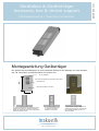
UT56 Grundprofil mit Ausschnitt SL 270mm
EP
-
10 Endplatte
WS
-
OT56 2er Blende 270mm
Gerätebox 2er
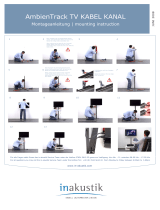
1.) Das Grundprofil des Geräteträgers an der
gewünschten Stelle an die Wand montieren.
Dabei den Ausschnitt über das Grundprofil der
Verbindungsleiste setzen.
2.) Die vorbestückte und
verdrahtete Gerätebox
einrasten und fixieren.
3.) Die Blende und die Endplatte des
Geräteträgers aufset
zen. Die Blenden
der Verbindungsleiste werden auf
Stoß angepasst.
Gerätebox & Geräteträger
Accessory box & device support
Montageanleitung | mounting instructions
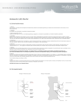
Montageanleitung Geräteträger
Der AmbienTrack Geräteträger ist eine komplette Einheit für die Montage von zwei Geräten
wie z.B. Steckdose und Netzwerkdose. Er besteht aus:

TRACK
AMBIEN
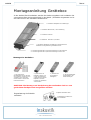
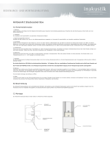
Montageanleitung Gerätebox
In der AmbienTrack Gerätebox werden die Geräte eingebaut und verkabelt. Die
vormontierte Box wird anschließend in der Wand- / Ecksäule eingerastet und in
der Höhe fixiert. Die Gerätebox besteht aus:
1 x Gerätebox Unterteil
1 x Gerätebox Oberteil mit / ohne Ausfräsung
1 x Gerätebox Endplatten mit Öffnungen. Bei Bedraf kann
zusätzlich eine Zugentlastung installiert werden
8
x Gerätebox Schrauben 3,5x16mm
2 x Arretierungsschrauben 3,9x16mm bei Montage in WS
-
UT56 bzw.
2 x Arretierungsschrauben 3,9x42mm bei Montage in ES-UT100
1 x Gerätebox Endplatten ohne Öffnungen
Montage der Gerätebox
1.) Die gewünschte
Gerätebestückung im Unterteil
der Gerätebox vornehmen und
verdrahten. Die Trageringe
müssen dabei in der Nut des
Unterteils einrasten.
2.) Kabel durch die
Endplatten führen und
mit der Zugentlastung
(separates Teil) fixieren.
Endplatten mit dem
Unterteil der Gerätebox
verschrauben.
3.) Das Oberteil
der Gerätebox
aufklippsen.
4.) Die Zentraleinsätze
(Zentralplatten) der
Geräte anbringen.
ACHTUNG: Die Montage und Verdrahtung der Gerätebox darf nur von
geschultem Fachpersonal ausgeführt werden!
Zugentlastung als Zubehör
erhältlich:
Zugentlastung Zubehör Art
.
Nr. 001999002
Endplatte Gerätebox offen

TRACK
AMBIEN
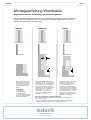
Montageanleitung Wandsäule
Allgemeiner Hinweis zur Montage der Verbindungsleiste:
Bei der Deckelmontage mit den End- oder Eckstücken beginnen damit mögl
ichtst
wenig bauseitige Schnittkanten zu sehen sind und diese möglichst hinter dem
Deckel der Wandsäule verschwinden
3
-
5 mm
22 mm
3
-
5 mm
Wand
-
und Ecksäulen mit
Ausschnitt SL verwenden.
Den jeweiligen Ausschnitt
über das Grundprofil der
Verbindungsleiste laufen
lassen.
Reihenfolge:
1. Grundprofil
Verbindungsleiste
2. Grundprofil WS
3. Deckel Verbindungsleiste
4. Decke Verbindungsleiste
(auf Stoß angepasst)
Wandsäulen OHNE Ausschnitt SL
verwenden und bis auf 22mm in die
Wand einlassen. 3 – 5mm Abstand
zum Grundprofil der Verbindungs-
leiste lassen damit die SL Blende
einrasten kann. Das Grundprofil der
Verbindungs-leiste unterhalb der
Wandsäule ca. 70 – 75mm
unterbrechen. An dieser Stelle
später die „SL Blende Übergang
Wandsäule“ verwenden.
Wandsäulen OHNE Ausschnitt SL
verwenden und bis auf den
Kragen in die Wand einlassen.
3 – 5mm Abstand zum
Grundprofil der Verbindungs-
leiste lassen damit die SL Blende
einrasten kann. Das Grundprofil
der Verbindungs-leiste unterhalb
der Wandsäule ca. 70 – 75mm
unterbrechen. An dieser Stelle
später die „SL Blende Übergang
Wandsäule“ verwenden.
Aufputz
Teilinputz
Inputz
Hinweis zu Teilinputz
-
und Inputzmontage:
Bei der Einbautiefe der Wandsäulen muss die Stärke des Wandputzes
berücksichtigt werden.
-Teilinputz: Schlitzung vertikal, 56mm gesamt (Achtung Wandbelag!)
- Inputz: Schlitzung vertikal (56mm)+ horizontal (23mm)

TRACK
AMBIEN
AmbienTrack - Pflegehinweise
Die Profile ausschließlich mit einem weichen Tuch reinigen. Bei starker Verschmutzung darf nur neutrales
Reinigungsmittel mit einem feuchten Tuch verwendet werden. Die Profile NIEMALS nass abwaschen!
WICHTIG:
Ausschließlich pH-neutrale Reiniger verwenden!
HOTLINE
Für alle Fragen zu AmbienTrack steht Ihnen das in-akustik Service-Team unter der
Hotline 07634 / 5610-22 zur Verfügung. Sie erreichen uns von Mo. – Fr. zwischen
08.00 Uhr – 17.00 Uhr
in-akustik GmbH & Co.KG
Untermatten 12-14
79282 Ballrechten-Dottingen
GERMANY
Tel.: +49 (0) 7634 / 5610-0
Fax.: +49 (0) 7634 / 5610-80
E-Mail: ambientech@in-akustik.com
WEB: www.in-akustik.com

TRACK
AMBIEN
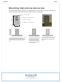
270
135
base profile 270 mm with a cutout
EP
-
10 end cap
WS
-
OT56 cover 2
gang 270mm
accessory box 2 gang
1.) Fit the base profile of the device box to the
desired location on the wall. Position the
cutout above the mounting rail of the joining
strip. Remove the cover of the base board
first.
2.) Insert the cables from the
base board into the socket and
wire them to the accessory
box. Clip the accessory box
with the previously equipped
and wired accessory box and
secure it in place.
3.) Put on the cover and the e
nd cap
of the device support. The covers of
the base board are changed so they
fit flush.
Mounting instructions device box
The AmbienTrack device support is a complete unit for mounting two pieces of equipment
such as a power socket and a network cable outlet. It comprises:

TRA
CK
AMBIEN
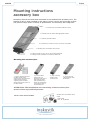
Mounting instructions
accessory box
Accessory devices are fitted and connected in the AmbienTrack accessory box. The
hooked up box is then installed in the wall or corner column and its height is fixed.
The product range offers a variety of possibilities. The accessory box comprises:
1 x
accessory box base section
1 x
accessory box top section with appropriate cutouts
1 x
accessory box end sections with a cutout
.
8 x
accessory box scr
ews 3.5 mm x 16 mm for end sections
2 x
locking screws 3.9 mm x 16 mm
for mounting WS
-
UT56
2 x locking screws 3,9x42mm for mounting in ES-UT100
1 x
accessory box end sections without a cutout
Mounting the accessory box
1.) Fit the required devices to
the base section of the
accessory box and connect the
cabling. Ensure that the
support rings of the fitted
devices slot into the groove of
the base section.
2.) Pull the cables
through the end
sections and fix them in
place with the strain
relief (separate item).
Screw the end sections
to the base section of
the accessory box.
3.) Clip on the top
section of the
accessory box.
4.) Secure the top
(central panel) of the
accessories.
ATTENTION: The installation and connecting of the accessory box
must be done by qualified persons.
Strain
-
relief also available
Strain
-
re
lief
Item- Nr. 001999002
accessory box end sections with a
cutout

TRACK
AMBIEN
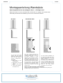
Montageanleitung Wandsäule
General guidelines for mounting the floor- / skirting board
Mount the end or corner sections first so that the cut edges can be seen only
minimally and these are hidden by the cover of the wall column.
3
-
5 mm
22 mm
3
-
5 mm
Use the wall
-
and corner
column with the cutout.
Position the relevant cutout
above the base profile of
the floor- / skirting board.
Sequence:
1. Base profile of floor-
/skirting board
2. Base p
rofile of the wall
column
3. cover of floor-/
skirting
board
4. cover of floor-/skirting
board (flush cut)
Use wall columns WITHOUT SL
cutout and mount flush into the
wall with a clearance of 22 mm to
the flange. Maintain 3 –
5 mm
distance to
the mounting rail of the
joining strip so that the SL cover
can click into place. Leave a 70 –
75
mm gap in the mounting rail of the
joining strip below the wall column.
You can insert a "SL wall column
connection cover" here later. Adjust
the flange of
the mounting rail so
that it has a clearance of 22 mm
from the wall.
Use wall columns WITHOUT the
SL cutout and mount them flush
into the wall all the way to the
flange. Maintain 3 –
5 mm
distance to the mounting rail of
the joining strip so that the SL
cover can click into place. Leave
a 70 –
75 mm gap in the
mounting rail
of the joining strip
below the wall column. You can
insert a "SL wall column
connection cover" here later.
On
-
wall
Partial In
-
wal
l
In
-
wall
Notes on in
-
wall and partial in
-
wall installation:
Take the thickness of the wall plaster into consideration when planning the
installation depth for the wall columns.

TRACK
AMBIEN
AmbienTrack - Cleaning &
maintenance advice
Please clean the surfaces of the profiles only with a soft cloth. Heavy soiling should be removed using a
neutral cleaner on a slightly moist cloth. The Profiles should NEVER be washed with soaking wet materials!
Important:
Please use ONLY non-aggressive, pH-neutral cleaning agents
HOTLINE
For all questions around AmbienTrack you may call the in-akustik Service-
Team under
the Hotline Tel.: +49-(0)7634 / 5610-23 from Monday to Friday between 8:00am to
5.00pm
in-akustik GmbH & Co.KG
Untermatten 12-14
79282 Ballrechten-Dottingen
GERMANY
Tel.: +49 (0) 7634 / 5610-0
Fax.: +49 (0) 7634 / 5610-80
E-Mail: ambientech@in-akustik.com
WEB: www.in-akustik.com
-
 1
1
-
 2
2
-
 3
3
-
 4
4
-
 5
5
-
 6
6
-
 7
7
-
 8
8


Inakustik AmbienTrack device support Bedienungsanleitung
- Typ
- Bedienungsanleitung
in anderen Sprachen
Verwandte Artikel
-
 Inakustik AmbienTrack TV cable duct Bedienungsanleitung
-
 Inakustik AmbienArt RGB Controller Bedienungsanleitung
-
 Inakustik AmbienTone No.3 Bedienungsanleitung
-
 Inakustik AmbienArt LED cube plug in base Bedienungsanleitung
-
 Inakustik AmbienArt LED end section Bedienungsanleitung
-
 Inakustik AmbienTone Sub 2 Bedienungsanleitung
-
Inakustik AmbienArt LED plug in base Bedienungsanleitung
-
 Inakustik AmbienTone No.1 Bedienungsanleitung
-
 Inakustik AmbienArt LED cubes Bedienungsanleitung


