
INSTRUCTIONS FOR INSTALLATION AND USE
MONTAGE- UND GEBRAUCHSANWEISUNG
INSTRUCTIONS POUR L'INSTALLATION ET L’UTILISATION
ISTRUZIONI PER L'INSTALLAZIONE E L’USO
INSTRUCCIONES PARA INSTALACIÓN Y USO
INSTRUÇÕES DE INSTALAÇÃO Y UTILIZAÇÃO
AANWIJZING VOOR GEBRUIK EN INSTALLATIE
Seite wird geladen ...

ENGLISH
DESCRIPTION
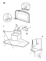
The unit can be found in filtering hoods, exhaust hoods or in hoods with an outside motor. In the Filtering hoods (Fig.
1) the air and steam taken up by the unit are purified with charcoal filters and returned to the environment through the
aeration grids on the side of the flue. WARNING: When using filtering hoods, both charcoal filters and an air deflector
must be used. Located in the upper part of the flue, this deflector recycles the air to the environment (Fig. 1A). In the
Exhaust hoods (Fig .2) an exhaust duct conveys the steam and cooking odors directly outside through the wall/ceiling.
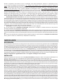
Therefore they do not require charcoal filters. In the hoods with an outside motor (Fig. 3), a vacuum suction unit must
be connected; this exhaust will operate separately, conveying the exhaust air through the unit. Only use vacuum units
suggested in the original catalogue.
INSTALLATION
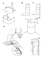
To facilitate installation, before starting remove the grease filter/s: press inward on the clamp at the handle and pull the
filter downward (Fig. 4/5).
Installation of a utensil holder (upon request): See Figure 6A or 6B depending on the model purchased. Install the
utensil holder with 4 flathead screws (supplied). Secure the 2 supports (C) to the hood, one on the left and one on the
right; insert the utensil holder into these supports. Keep a good grip on it until you have installed, and secured, at least
one of the 2 supports (D) at the top of the hood.
Installation on the wall (Fig. 7): Using the special drilling template, drill the required holes in the wall. As previously
specified in the chapter “Warning” remember there must be a minimum of 650 mm between the bottom edge of the hood
and the stop of the stove. Secure the metal bracket (B) to the wall using the screws and plugs (bracket, screws and plugs
are all supplied with the unit). Use the 2 triangles cut into the bracket to position it precisely along the vertical axis of
the hood. Then set the hood onto the bracket. Adjust the horizontal position, shifting the hood to the right or left as needed
lining it up with the wall units. If the height of the hood also requires adjustment, use the special regulation screws (V)
(supplied). Once regulation has been completed, finish securing the hood with 4 more screws (M): mark the points for
the 4 holes on the wall, remove the hood and drill (8mm diameter holes); then use the plugs and screws to complete
installation.
Installation with rear panel (Fig. 8): The rear panel is positioned at the top of the stove, flush against the wall. Rest
the lower edge of the panel behind the stove and anchor the upper edge to the wall using the two holes found on the panel.
Insert the screws and plugs provided (A). The unit is secured to the rear panel as though it were being installed on the
wall: use the supplied metal bracket (B) and the screws and plugs supplied with the panel.
Securing the extension flues: Basic installation requirements: – Set the electrical power supply within the space covered
by the decorative flues. – If your unit is installed in an Exhaust hood or in a hood with outside motor, prepare the air exhaust
hole.
When installing exhaust hoods and hoods with outside motor, to achieve the best possible conditions use an air exhaust
pipe that : i) is as short as possible, ii) has a minimum of curves (maximum angle: 90°), iii) is made of a material that
complies with the standards (which vary from nation to nation) and iv) is smooth on the inside. It is also advisable to
avoid any drastic changes in pipe section (diameter: 150 mm).
Adjust the width of the extension flue support bracket (W) using screws A indicated in Fig. 9. Then use the plugs and
screws provided to secure it to the ceiling. Make certain it is aligned with the hood. For filtering hoods, the air exhaust
grids are positioned in the upper part (Fig. 10). For exhaust hoods, turn the upper flue over so that the air exhaust grid
is in the lower section (Fig. 11).
Be very careful when handling the telescopic flues, especially when resting these on the hood body,
to prevent scratching.
Exhaust hoods and hoods with outside motors: Connect the hood flange to the exhaust hole in the wall/ceiling using a
flexible pipe. Only for models with outside motor (Fig. 12): plug the hood into the outside control unit using the special
terminal block: remove wire clamp A and lid B from the wiring junction box. Secure the wire connecting the control unit
to terminal C. Then replace wire clamp A and lid B on the wiring junction box. The other end of the wire is secured to the
terminal block on the outside control unit. Plug in the hood. Insert the extension pipes setting them on the hood; extend
the upper flue to the ceiling and secure with the 2 screws (G) - Fig. 13.
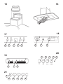
Filtering hood: Secure the deflector to the upper flue using the 4 special screws (provided) – Fig. 14; hook up the flexible
pipe (diameter: 125) to the deflector. Install the reduction (provided) on the hood air outlet point (Fig. 15). Take the 2
assembled extension flues and set them on the hood; extend the upper flue to the ceiling and secure with the 2 screws
(G) - Fig. 13. Extend the lower flue taping it in place and then connect the flexible pipe to the hood reduction. Plug in
the hood. Extend the lower flue downward setting it against the hood. Install the charcoal filters by pressing the 2 tabs
on the filter down into the special housing (Fig. 16) and rotating upward.
OPERATION
Depending on the model, the unit is equipped with the following controls:
Controls shown in Fig. 17: Button A = turns the lights on/off. Button B = turns the TIMER on/off: press once to turn
the timer on, therefore, after 5 minutes, the motor cuts out (at the same time the selected speed blinks on the display);
the timer remains on if the motor speed is changed. Display C = - indicates the selected motor speed (from 1 to 4); -
Seite wird geladen ...
Seite wird geladen ...

FUNKTIONSWEISE
Je nach Version ist das Gerät mit folgenden Bedienung ausgestattet:
Bedienung gemäß Abb. 17: Taste A = LICHT einschalten/ausschalten. Taste B = TIMER einschalten/ausschalten: Beim
ersten Drücken wird der Timer aktiviert und nach 5 Minuten kommt der Motor zum Stillstand (wobei gleichzeitig auf dem
Display die Zahl für die gewählte Geschwindigkeit aufblinkt); der Timer bleibt in Funktion, wenn sich die Motorgeschwindigkeit
ändert. Display C = - Anzeige der gewählten Motorgeschwindigkeit (von 1 bis 4); - Anzeige der Timerauslösung durch
Aufblinken der Nummer; - Anzeige des Filteralarms, wenn das mittlere Segment sich einschaltet oder blinkt.
Taste D = Schaltet den Motor ein (in der zuletzt eingestellten Geschwindigkeit). Wird die Taste nochmals gedrückt, so
werden nacheinander die Gesch-windigkeiten 1-4 des Motors eingeschaltet. Wird die Taste ungefahr 2 Sekunden lang
gedrückt, so kommt der Motor zum Stillstand. Taste R = Reset der Fett- und der Kohlefilter. Bei Eintritt des Filteralarms
(Einschalten des mittleren Segments auf dem Display) sind die Fettfilter (nach 30 Betriebsstunden) zu reinigen. Blinkt
das mittlere Segment auf, so sind die Fettfilter zu reinigen und die Kohlefilter zu ersetzen (nach Ablauf von 120
Betriebsstunden). Wenn hingegen Ihre Haube keine Umluftversion ist und daher keine Kohlefilter hat, sind nur die Fettfilter
zu reinigen, egal ob das mittlere Segment ununterbrochen angezeigt wird oder nur blinkt. Die Filteranzeige leuchtet bei
ausgeschaltetem Motor und ist ungefähr 30 Sekunden lang sichtbar. Zur Wiederaufnahme der Stundenzählung muss die
Taste 2 Sekunden lang gedrückt werden während die Anzeige blinkt.
Bedienung gemäß Abb. 18/19: Schalter A : LICHT; Position 0: Licht an, Position 1: Licht aus.
Schalter B - MOTORGESCHWINDIGKEIT: Möglichkeit die Regulierung der Betriebsgeschwindigkeit des Motors. Position
0: Motor im Stillstand. C : Motorfunktionsanzeige.
Bedienung gemäß Abb. 20: Schalter A: Beleuchtung. Schalter B: Ein- (erste Betriebstufe), Aus- Schalter.
Schalter C: zweite Betriebstufe. Schalter D: dritte Betriebstufe. Schalter E: Motorkontrolleuchte.
Bedienung gemäß Abb. 21: Taste A: Licht einschalten/ausschalten; alle 30 Betriebsstunden leuchtet die
zutreffende Anzeige (S) auf und dies bedeutet, dass die Fettfilter zu reinigen sind; alle 120 Betriebsstunden blinkt
die zutreffende Anzeige (S) auf und dies bedeutet, dass die Fettfilter gereinigt und die Kohlefilter ersetzt werden
müssen. Zur Wiederaufnahme der Stundenzählung (RESET) muss die Taste A circa 1” lang gedrückt werden
(während die Anzeige S eingeschaltet ist). Taste B: Schaltet den Motor mit der Geschwindigkeit 1 ein (die
zutreffende Anzeige leuchtet auf); hält man die Taste circa 1” lang gedrückt, wird der Motor ausgeschaltet; wird
die Taste ein zweites Mal betätigt (während die Anzeige leuchtet), erfolgt die Aktivierung des TIMERS und nach
5’ kommt der Motor zum Stillstand (die Anzeige blinkt). Taste C: Schaltet den Motor mit der Geschwindigkeit 2
ein (die zutreffende Anzeige leuchtet auf); wird die Taste ein zweites Mal betätigt (während die Anzeige leuchtet),
erfolgt die Aktivierung des TIMERS und nach 5’ kommt der Motor zum Stillstand (die Anzeige blinkt). Taste D:
Schaltet den Motor mit der Geschwindigkeit 3 ein (die zutreffende Anzeige leuchtet auf); wird die Taste ein zweites
Mal betätigt (während die Anzeige leuchtet), erfolgt die Aktivierung des TIMERS und nach 5’ kommt der Motor zum
Stillstand (die Anzeige blinkt).
Taste E: Schaltet den Motor mit der Geschwindigkeit 4 ein (die zutreffende Anzeige
leuchtet auf); wird die Taste ein zweites Mal betätigt (während die Anzeige leuchtet) erfolgt die Aktivierung des
TIMERS und nach 5’ kommt der Motor zum Stillstand (die Anzeige blinkt).
Mit besonderer Sorgfalt sind die Fettfilter zu behandeln: Hat das von Ihnen erworbene Modell die in Abb.
17 dargestellten Bedienung: die Fettfilter sind jeweils nach etwa 30 Betriebsstunden zu reinigen (wenn das mittlere
Segment auf dem Display ununterbrochen aufleuchtet oder blinkt). Entfernung der Filter: Den Festhalter in der Nähe
des Griffs nach innen drücken und den Filter nach unten ziehen. Die Filter mit einem neutralen Reiniger waschen.
Nach Wiedereinsetzen der gereinigten Filter 2 Sekunden lang die Taste R (Reset) drücken, damit die Zählung neu
beginnt. Weitere Informationen erhalten Sie unter dem Stichwort „Bedienung“ von Abb. 17 im Abschnitt “Funktionsweise“.
Hat das von Ihnen erworbene Modell die in Abb. 18/19/20 dargestellten Bedienung: Der Fettfilter ist periodisch in
Abhängigkeit vom Gebrauch (mindestens jedoch alle zwei Monate) zu reinigen. Entfernung des Filters: Den
Festhalter in der Nähe des Griffs nach innen drücken und den Filter nach unten ziehen. Die Filter mit einem neutralen
Reiniger waschen. Hat das von Ihnen erworbene Modell die in Abb. 21 dargestellten Bedienung: die Fettfilter sind
jeweils nach etwa 30 Betriebsstunden zu reinigen (wenn die Anzeige der Lichttaste aufleuchtet - Abb. 21S).
Entfernung der Filter: Den Festhalter in der Nähe des Griffs nach innen drücken und den Filter nach unten ziehen.
Die Filter mit einem neutralen Reiniger waschen. Sind die Filter wieder eingesetzt, zur Wiederaufnahme der
Stundenzählung circa 1” lang die Taste Licht (Abb. 21A) gedrückt halten, während die Anzeige (S) leuchtet. Weitere
Informationen erhalten Sie unter dem Stichwort „Befehle“ von Abb. 21 im Abschnitt “Funktionsweise“.
Ersatz der Kohlefilter: Wird ein Gerät in Umluftversion eingesetzt, so müssen die Kohlefilter ersetzt werden: Den
Festhalter nach innen drücken (Abb. 16) und nach unten drehen, bis die beiden Filterzungen aus ihrem Sitz entfernt werden
können. Hat das von Ihnen erworbene Modell die in Abb. 17 dargestellten Bedienung, müssen Sie die Kohlefilter dann
ersetzen, wenn das mittlere Segment aufblinkt (d. h. nach jeweils 120 Betriebsstunden). Hat das von Ihnen erworbene
Modell die in Abbildung 18/19/20 dargestellten Bedienung, müssen Sie die Kohlefilter in Abhängigkeit vom Gebrauch im
Durchschnitt alle 6 Monate ersetzen. Hat das von Ihnen erworbene Modell die in Abb. 21 dargestellten Bedienung, müssen
Sie die Kohlefilter austauschen, wenn die Anzeige der Lichttaste (Abb.21S) blinkt, d. h. alle 120 Betriebsstunden).
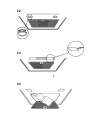
Beleuchtung: Gemäß dem von Ihnen erworbenen Modell ist Abb. 22, Abb. 23 oder Abb. 24 zu konsultieren.
Abb. 22: Zur Entfernung der Halogenbirnen ist die Fassung entgegen dem Uhrzeigersinn zu drehen. Setzen Sie
Ersatzbirnen desselben Typs ein.
Abb. 23: Zum Ersetzen der Glühlampen den Fettfilter herausnehmen, um an das innere des Geräts zu gelangen; die
Schraube lösen, die Deckenleuchte blockiert, dann im Inneren der Haube den Bolzen der Deckenleuchte ins Innere des
Geräts drücken; die Lampe durch eine neue des gleichen Typs ersetzen.

Abb. 24: Falls Ihr Gerät die auf der Abbildung 24 wiedergegebene Art der Beleuchtung aufweist, für den Wechsel der
Glühlampen Rost des Fettfilters öffnen und entfernen; die Lampe durch eine neue des gleichen Typs ersetzen.
FRANCAIS
DESCRIPTION
L'appareil peut être en version recyclage, en version aspirante, ou en version avec moteur extérieur. Dans la version
Recyclage (Fig. 1), l’air et les vapeurs convoyés par l’appareil sont épurés par les filtres à charbons et remis en circulation
à travers les grilles latérales d’aération du tuyau. ATTENTION: Pour la version Recyclage utiliser les filtres à charbons
et un déflecteur placé dans la partie haute du conduit permettant la circulation de l’air dans le local (Fig. 1A). Dans la version
Aspirante (Fig. 2), les vapeurs et les odeurs de la cuisine sont convoyées directement à l’extérieur par un tuyau
d’évacuation à travers la paroi/plafond. Il n’est donc pas nécessaire d’utiliser les filtres à charbons. Dans la version avec
moteur extérieur (Fig. 3) l'appareil doit être relié à un moteur extérieur séparée. Il sert de base d'installation d'évacuation
de l'air. Employer uniquement les moteurs proposés dans le catalogue original.
INSTALLATION
Avant de procéder aux opérations de montage, pour manoeuvrer plus aisément l’appareil, démontez les filtres à graisse:
à l'aide de la poignée, pousser l’arrêt vers l’intérieur et tirer le filtre vers le bas (Fig. 4/5).
Montage du porte-louches (en option) : Voir la Figure 6A ou 6B, suivant le modèle que vous avez acheté. Pour le montage
du porte-louches il faut utiliser 4 vis à tête plate (fournies). Fixer les 2 supports (C) à la hotte, un sur le côté droit et l’autre
sur le côté gauche, puis placer le porte-louches dessus et continuer à le tenir tant que vous n’avez pas monté au moins
l’un des 2 autres supports (D) que vous devrez fixer sur le côté avant de la hotte.
Fixation murale (Fig. 7): En utilisant le gabarit de perçage spécial faites les trous dans le mur. Comme indiqué au chapitre
«Attention», ne pas oublier que la distance entre le bord inférieur de la hotte et le plan de cuisson doit être au minimum
de 650 mm. Fixer le support métallique (B) au mur à l’aide des vis et des chevilles (support, vis et chevilles sont fournis
en équipement). Utiliser les deux petits triangles découpés sur le support afin de le placer exactement le long de l’axe
vertical de la hotte. Ensuite, accrocher la hotte au support. Régler la position horizontale de l’appareil en déplaçant la
hotte vers la droite ou vers la gauche suivant les exigences d’alignement des meubles suspendus. S’il faut aussi régler
la hotte en hauteur, agir sur les vis (V) de réglage (fournies en équipement). Après avoir réglé, fixer définitivement la hotte
à l’aide de 4 autres vis (M): tracer sur le mur l’emplacement des 4 trous à percer, décrocher la hotte et percer les trous
(diamètre 8 mm) ; ensuite utiliser les chevilles et les vis fournies en équipement pour la fixation définitive.
Fixation avec panneau arrière (Fig. 8): Le panneau arrière sera placé contre le mur, dans la partie supérieure de la
table de cuisson. Appuyez le bord inférieur du panneau derrière la table de cuisson et ancrez le bord supérieur au mur
par les deux trous prévus dans le panneau, en y introduisant les vis et les chevilles fournis (A). La fixation de l’appareil
au panneau arrière a lieu de la façon que la fixation murale, en utilisant le support métallique fourni en équipement (B),
ainsi que les vis et les chevilles fournies avec le panneau.
Fixation des tuyaux télescopiques: Conditions essentielles pour le montage: – Prévoyez l’alimentation électrique à
l’intérieur du tuyau télescopique. – Si l'appareil doit être installé en version Aspirante ou en version avec moteur extérieur,
prévoyer le trou d’évacuation de l’air.
Pour obtenir des conditions optimales, vous devez, pour ce qui concerne la version aspirante et la version avec moteur
extérieur, employer un tuyau d’évacuation qui ait: une longueur suffisante, le moins de courbes possible (l'angle maximum
des courbes ne doit pas dépasser 90°), soit fait d'une matière approuvée par la loi (qui peut varier selon les Etats), partie
interne le plus lisse possible. De plus, nous vous conseillons d’éviter des changements brusques de section du tuyau
(diamètre conseillé: 150 mm).
Réglez la largeur de l’étrier du support (W) du tuyau télescopique au moyen des vis A indiquées dans la Fig. 9. Puis fixez-
le successivement au plafond, au moyen des chevilles et des vis qui vous sont fournies, en faisant de sorte qu’il soit
dans l’axe de votre hotte. Pour la version recyclage, les grilles d’évacua-tion de l’air doivent être positionnées dans la
partie haute (Fig. 10). Pour la version aspirante retournez le tuyau supérieur de façon à ce que les grilles d'évacuation
d'air soit dans la partie du bas (Fig. 11).
Faire particulièrement attention lors de la manoeuvre des tuyaux télescopiques, surtout au moment de les
appuyer sur le corps de la hotte, afin d’éviter de les rayer.
Version aspirante et version avec moteur extérieur: Raccordez la bride de la hotte au trou d’éva-cuation sur le
mur/plafond, au moyen d’un tuyau flexible.
Seulement pour la version avec moteur extérieur (Fig. 12): faire la connexion électrique entre le moteur extérieur
et la hotte en utilisant les plaques de jonction appropriées: enlever l'élément A et le couvercle B de la boîte de
connexion; fixer le cable de raccordement du moteur à la plaque de jonction C. Remonter l'élément A et le couvercle
B de la boîte de connexion; l'autre extrémité du câble doit être fixée à la plaque de jonction du moteur extérieur.
Effectuez le raccordement électrique de la hotte au moyen du câble d'alimentation.
Installer les tuyaux télescopiques en les appuyant sur la hotte ; soulever le tuyau supérieur jusqu’au plafond et le fixer
à l’aide des 2 vis (G) – Fig. 13.
Versione recyclage: Fixer le déflecteur au tuyau supérieur à l’aide des 4 vis (fournies en équipement) - Fig. 14; raccorder
un tuyau souple, de 125 de diamètre, au déflecteur. Monter la réduction (en équipement) sur la hotte en face du point
Seite wird geladen ...
Seite wird geladen ...
Seite wird geladen ...
Seite wird geladen ...
Seite wird geladen ...
Seite wird geladen ...
Seite wird geladen ...
Seite wird geladen ...
Seite wird geladen ...
Seite wird geladen ...
Seite wird geladen ...

7
B
V
M
C
D
A
8
B
6B

9
=
=
W
A
10 11
12
13
G
14
A
B
C

17
A B D RC
A BC
15 16
18
20
19
B
C
A
A
B
C
D
E
21
A B
D E
C
S

22
23
24


04306506/2 - Kbasse sen.nor.
-
 1
1
-
 2
2
-
 3
3
-
 4
4
-
 5
5
-
 6
6
-
 7
7
-
 8
8
-
 9
9
-
 10
10
-
 11
11
-
 12
12
-
 13
13
-
 14
14
-
 15
15
-
 16
16
-
 17
17
-
 18
18
-
 19
19
-
 20
20
-
 21
21
-
 22
22
-
 23
23
-
 24
24


in anderen Sprachen
- English: Candy CDH 90 W User manual
- français: Candy CDH 90 W Manuel utilisateur
- español: Candy CDH 90 W Manual de usuario
- italiano: Candy CDH 90 W Manuale utente
- Nederlands: Candy CDH 90 W Handleiding
- português: Candy CDH 90 W Manual do usuário
Verwandte Artikel
Andere Dokumente
-
ROSIERES RDR 61 RUV Bedienungsanleitung
-
Groupe Brandt HM9971E1 Bedienungsanleitung
-
Zanussi ZHC911X Benutzerhandbuch
-
-
Best BHC91420CA Benutzerhandbuch
-
-
Hoover HDI90 Benutzerhandbuch
-
-
-