
GEMÜ Gebr. Müller Apparatebau GmbH & Co. KG · Fritz-Müller-Str. 6-8 · D-74653 Ingelfi ngen-Criesbach
Telefon +49(0)7940/123-0 · Telefax +49(0)7940/123-192 · [email protected] · www.gemu-group.com
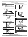
Feldbusanschluss
Feldbusanschluss
GEFAHR
Gefahr durch Stromschlag!
Kurzschluss.
Elektrischer Anschluss nur durch Elektro-
Fachkraft.
Kabel vor elektrischem Anschluss spannungsfrei
schalten.
1. Gerätesteckdose 1 und Flachkabel 2 bereithalten.
12
Gerätesteckdose und Flachkabel
2. Befestigungsschraube 3 mit Schraubendreher von
Gerätesteckdose 1 lösen.
1
3
Befestigungsschraube lösen
3. Gerätedeckel 4 von Gerätesteckdose 1 abnehmen.
1
4
Gerätedeckel abnehmen
4. Gelbes und schwarzes Flachkabel 2 in Aussparungen des
Gerätedeckels 4 legen.
2
4
Flachkabel einlegen
UNTERNEHMENSBEREICH
VENTIL-, MESS- UND REGELSYSTEME
4190, 4192
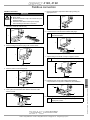
5. Isolationsstücke 5 mit geeignetem Werkzeug aus
Gerätesteckdose 1 entfernen.
5
1
Isolationsstücke entfernen
6. Gerätedeckel 4 und Flachkabel 2 mit Gerätesteckdose 1
verbinden.
+Die Pins der Gerätesteckdose werden automatisch
mit den Flachkabeln verbunden.
1
4
2
Gerätedeckel verschrauben
7. Befestigungsschraube 3 mit ca. 0,6 Nm anziehen.
+Ein zu hohes Drehmoment kann zum Ausreißen
des Gewindes führen.
1
6
3
Befestigungsschraube anziehen
8. Leitungsenden der Flachkabel 2 installationsgerecht mit
Isolationsstücken 5 isolieren.
5
2
9. Gerätesteckdose 1 und Dichtung 6 auf Gerätestecker
stecken.
+Anzeige von AS-Interface Spannung und
Ausgangssignal erfolgt über LEDs.

Änderungen vorbehalten · Subject to alteration · 05/2014 · 88442661
VALVES, MEASUREMENT
AND CONTROL SYSTEMS
GEMÜ Gebr. Müller Apparatebau GmbH & Co. KG · Fritz-Müller-Str. 6-8 · D-74653 Ingelfi ngen-Criesbach
Telefon +49(0)7940/123-0 · Telefax +49(0)7940/123-224 · [email protected] · www.gemu-group.com
Fieldbus connection
Fieldbus connection
DANGER
Risk of electric shock!
Short-circuit.
Electrical connection only to be carried out by an
electrical expert.
Disconnect the cable from the power supply
before making the electrical connection.
1. Have plug 1 and fl at cable 2 ready.
12
Plug and fl at cable
2. Remove fi xing screw 3 from plug 1 with a screw driver.
1
3
Removing the fi xing screw
3. Remove device cover 4 from plug 1.
1
4
Removing the device cover
4. Insert yellow and black fl at cable 2 in the recesses of the
device cover 4.
2
4
Inserting the fl at cable
4190, 4192
5. Remove insulation components 5 from plug 1 using an
appropriate tool.
5
1
Removing insulation components
6. Connect device cover 4 and fl at cable 2 with plug 1.
+The pins of the plug are automatically connected
with the flat cables.
1
4
2
Bolting the device cover in place
7. Tighten fi xing screw 3 with a torque of approx. 0.6 Nm.
+If the torque is too high the thread may be stripped.
1
6
3
Tightening the fi xing screw
8. Insulate the wire ends of fl at cable 2 with insulation
components 5 in a way that is suitable for the installation.
5
2
9. Push plug 1 and seal 6 onto the connector plug.
+The AS interface voltage and output signal are
displayed by LEDs.
-
 1
1
-
 2
2

