
Form No. 38030-69 Revised 6/30/16 © 2016 by Bobrick Washroom Equipment, Inc. Printed in U.S.A.
In Europe: BOBRICK WASHROOM EQUIPMENT, LTD.
2 The Hangar, Perseverance Works, 38 Kingsland Road, London, E2 8DD, UK
• Tel: +44 (0)20 8366 1771 • Fax: +44 (0)20 8363 5794
In the U.S.A.: BOBRICK WASHROOM EQUIPMENT, INC.
6901 Tujunga Avenue, North Hollywood, California 91605-6213
• Tel: (818) 764-10000 • FAX: 818-503-9941 or email inter[email protected]
IMPORTANT NOTES:
For proper electrical connections, check local building codes. Unit must
be installed by a qualied licensed electrician.
Warm air hand dryer is intended for use in an indoor environment by non-
expert users.
This appliance can be used by children aged from 8 years and above
and persons with reduced physical, sensory or mental capabilities or
lack of experience and knowledge if they have been given supervision or
instruction concerning use of the appliance in a safe way and understand
the hazards involved. Children shall not play with the appliance. Cleaning
and user maintenance shall not be made by children without supervision.
Electronic automatic dryer sensor will pick up movement within 100mm
(4") of the air outlet opening.
WARNING: In the xed wiring must be incorporated a disconnection
device. Dryer must be grounded (earthed).
SAFETY WARNING
Installation and wiring must conform to current local regulations
and building codes. Unit must be installed by a qualified
electrician. Turn off electrical power supply before making
electrical connections. If the unit fails or malfunctions, it
should be disconnected from the power supply and a qualified
electrician should be called. To avoid potential injury, the
building owner or maintenance personnel should remove the
unit from service if the dryer cover is missing or damaged.
INSTRUCTIONS FOR INSTALLATION AND MAINTENANCE
B-38030 230V RECESSED PAPER TOWEL DISPENSER,
AUTOMATIC HAND DRYER AND WASTE BIN (3-IN-1 UNIT)

Figure 1
Form No. 38030-69 Revised 6/30/16 © 2016 by Bobrick Washroom Equipment, Inc. Printed in U.S.A.
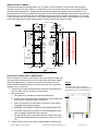
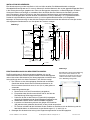
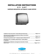
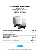
INSTALLATION OF CABINET:
Provide framed rough wall opening 362mm (14-1/4") wide x 1412mm (55-9/16") high. Minimum recessed depth
required to nish face of wall is 100mm (4"). Allow clearance for construction features that may protrude into rough
wall opening from opposite wall. Coordinate with mechanical engineer to avoid pipes, vents and conduits. If unit
projects above top of wainscot, provide channel or other ller to eliminate gap between cabinet ange and nish face
of wall. Mount unit in wall opening with shims between framing and cabinet at all points indicated by an “S” in Figure
1, then secure unit with 4.2 x 32mm (#8 x 1-1/4") sheet-metal screws (not furnished). Provide electrical service from
nearest distribution panel to dryer mounting base in conformance with local electrical codes.
ELECTRICAL CONNECTION OF HAND DRYER:
Electrical supply entry holes are located in the rear of the cabinet at lower right
corner of the dryer mounting base and at the right side of the cabinet. Supply
cable with supplementary insulation into one of these locations in the unit
cabinet. Cabinet should be tted with a conduit connection. Plastic grommet
supplied to use as necessary.
1. Connect dryer to nearest distribution panel. Use wire as required by local
electrical code, 3.31mm² dia. (No. 12) wire or larger.
2. Wiring Instructions:
a. This appliance is intended for connection to xed wiring.
b. A fused means for disconnection in all poles must be provided in the
xed wiring in accordance with the wiring rules.
c. Check that the electrical rating shown on the dryer (rating label) is
compatible with the electrical supply.
d. WARNING: THIS PRODUCT MUST BE GROUNDED (EARTHED).
e. Installation and wiring must conform to current IEE Regulations (UK),
local or appropriate regulation (other countries).
f. For 208–240 Volt dryers: Connect ground/earth supply the terminal
marked and the 208-240 Volt wires to terminals marked L (L1) and N
(L2).
3. Secure electrical wire in strain relief clamp provided on mounting base.
Figure 2
To remove dryer cover, remove two
screws from the bottom of the Dryer and
two from the sides, as shown in Figure 2.
396mm
15- 5/8"
SS
S S S
S
Recommended Mounting Height Off Floor
for United Kingdom BS8300:2009
1567 to 1674mm 61-11/16" to 65-7/8"
219mm
8-5/8"
89mm
3-1/2"
Ty p .
22mm
.88"
Diameter
Hole for
Between-Wall
Wirirng
1450mm
57-1/16"
Dryer
Sensor
Dryer
Outlets
Lock
& Key
Removable
Waste Bin
25mm
1"
Ty p .
346mm
13-5/8"
Finish Face of Floor
Paper
To w e l
Dispenser
96mm
3-13/16"
280mm
11"
Finish Face of Wall
14mm
9/16"
Ty p .
280mm
11" 62mm
2-7/16"
407mm
16"
34mm
1-3/8"
Ty p .
16mm
5/8"
22mm
.88"
Diameter
Hole for
Between-Wall
Wirirng
1398mm
55"
100mm
3-15/16"
Recommended Mounting Height Off Floor
for Australian DDA standards, AS1428.1-2009
1667 to 1774mm 65-5/8" to 69-13/16"
727mm
28-5/8"

Spare Parts List:
38030-2 Door Assembly (Upper)
38030-26 Door Assembly (Lower)
4369-175 TowelMate® Support Rod
38030-29 Waste Bin
38030-25 Lock & Key (Cat 74)
38030-23 Lock Mounting Plate Assembly with Tape
38030-36 Dryer Assembly 230V
38030-55 Activation Sensor Assembly
38030-40 Nozzle Assembly, Left
38030-41 Nozzle Assembly, Right
Form No. 38030-69 Revised 6/30/16 © 2016 by Bobrick Washroom Equipment, Inc. Printed in U.S.A.
CHECK DRYER OPERATION:
1. Turn electrical power supply on.
2. Position hands under air outlet, within 100mm (4") of air outlet opening.
3. Dryer should turn on. Warm air should blow from air outlet.
4. Remove hands from under air outlet and dryer should stop (within 2 seconds).
GENERAL OPERATING CONDITIONS:
The following minimum machine operating environmental parameters must be met in order to allow proper dryer
operation:
1. The equipment will operate correctly in its intended ambient operating temperature range, at a minimum,
between +5°C (41°F) and +40°C (104°F).
2. The equipment will operate correctly within a relative humidity environment at 50%RH, +40°C (104°F). Higher
RH may be allowed at lower temperatures. Measures shall be taken by the Purchaser to avoid the harmful
effects of occasional condensation.
3. The equipment will operate correctly up to 2000m (6,560ft) above mean sea level.
4. The equipment will operate in a normal ofce type Pollution Degree 2 environment.
5. The mains supplies in this equipment are designed to work at +/-10% voltage uctuation of the marked rating.
MAINTENANCE:
WARNING: Motor laminations are live. Turn electrical power supply off
before doing any maintenance or service to dryer. Electrical power supply
must be off unless dryer cover is secured.
1. Turn electrical power supply on.
2. Position hands under air outlet, within 100mm (4'') of air outlet
opening.
3. If a fault develops, disconnect the electrical supply; a qualied
electrician should be called.
4. There are no serviceable parts on the dryer. Return faulty dryer to
manufacturer noted below.
NOTE: If dryer is installed where there is a lot of dust and dirt in the air,
the interior of the dryer should be cleaned out frequently.
PRODUCT INFORMATION:
Model No. B-38030 230V: 208–240V AC, 3.6-4.0 Amp, 750-950 Watts, 50/60 Hz, Single Phase, VDE approved, CE
Marked, cUListed, Meets Electrical Safety Requirement: AS/NZ 60335.2.23:2004.
Product weight: 16.5kg (36.5 Lbs.)

In Europa: BOBRICK WASHROOM EQUIPMENT, LTD.
2 The Hangar, Perseverance Works, 38 Kingsland Road, London, E2 8DD, UK
• Tel: +44 (0)20 8366 1771 • Fax: +44 (0)20 8363 5794
In den USA: BOBRICK WASHROOM EQUIPMENT, INC.
6901 Tujunga Avenue, North Hollywood, California 91605-6213
• Tel: (818) 764-10000 • FAX: 818-503-9941 or email [email protected]
WICHTIGE HINWEISE:
Die elektrischen Anschlüsse müssen den örtlichen Bauvorschriften
entsprechen. Das Gerät muss von qualiziertem Personal (Elektriker)
installiert werden.
Der Warmluft-Händetrockner ist für die Benutzung innerhalb von
Gebäuden vorgesehen und seine Bedienung bedarf keiner besonderen
Vorkenntnisse.
Dieses Gerät kann von Kindern ab dem 8. Lebensjahr und von Personen
mit körperlichen, sensorischen oder geistigen Einschränkungen
oder mit wenig Erfahrung und Kenntnissen bedient werden, wenn
sie dabei beaufsichtigt werden oder in der sicheren Bedienung des
Geräts unterwiesen wurden und die damit verbundenen Gefahren
kennen. Dieses Gerät ist kein Spielzeug für Kinder. Die Reinigung und
Instandhaltung durch Kinder darf nicht unbeaufsichtigt erfolgen.
Der elektronische Sensor des automatischen Trockners erfasst
Bewegungen innerhalb eines Bereichs von 100 mm von der
Luftaustrittsöffnung.
WARNUNG: In der festverlegten Stromversorgung muss eine
Trennvorrichtung vorgesehen sein. Der Trockner muss geerdet werden.
SICHERHEITSWARNUNG
Installation und Verdrahtung müssen gemäß den gültigen
lokalen Bestimmungen und Bauvorschriften erfolgen. Das Gerät
muss von einem qualifizierten Elektriker installiert werden.
Vor dem Herstellen der elektrischen Anschlüsse muss die
Stromversorgung ausgeschaltet werden. Bei einer Störung oder
Fehlfunktion des Geräts ist dieses von der Stromversorgung
zu trennen und es muss ein qualifizierter Elektriker verständigt
werden. Um potenzielle Verletzungen zu vermeiden, muss der
Gebäudeeigentümer oder das Wartungspersonal das Gerät
außer Betrieb nehmen, wenn die Trocknerabdeckung fehlt oder
beschädigt ist.
INSTALLATIONS - UND WARTUNGSANWEISUNG
B-38030 230V (3-IN-1) PAPIERHANDTUCHSPENDER, AUTOMATISCHER
HÄNDETROCKNER UND ABFALLBEHÄLTER FÜR DEN WANDEINBAU
Form No. 38030-69 Revised 6/30/16 © 2016 by Bobrick Washroom Equipment, Inc. Printed in U.S.A.

396mm
15- 5/8"
SS
S S S
S
Empfohlene Installationshöhe vom OKFF,
Großbritannien BS8300:209
1567 mm bis 1674 mm
219mm
8-5/8"
89mm
3-1/2"
Ty p .
1450mm
57-1/16"
Trocknersensor
Trockner
Auslassöffnungen
Schloss
und Schlüssel
Herausnehmbarer
Abfallbehälter
25mm
1"
Ty p .
346mm
13-5/8"
von OKFF
Papier-
handtuchspender
96mm
3-13/16"
280mm
11"
Wandoberfläche
14mm
9/16"
Ty p .
280mm
11" 62mm
2-7/16"
407mm
16"
34mm
1-3/8"
Ty p .
16mm
5/8"
22mm
,88
ø Kabeleinführung
für UP-Verdrahtung
1398mm
55"
100mm
3-15/16"
Empfohlene Installationshöhe vom OKFF gemäß
australischen DDA-Standards, AS1428.1-2009
1667 mm bis 1774 mm
22mm
,88
ø Kabeleinführung
für UP-Verdrahtung
727mm
28-5/8"
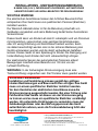
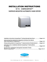
INSTALLATION DES GEHÄUSES:
Eine Wandaussparung mit 362 mm Breite x 1412 mm Höhe vorsehen. Die Mindesteinbautiefe zur fertigen
Wandoberäche beträgt 100 mm. Es muss ein Abstand für bauliche Merkmale, die aus der gegenüberliegenden Wand
in die Öffnung herausragen, gegeben sein. Einbau mit Bauingenieur besprechen, um Beschädigungen an Rohren,
Lüftungsschächten und Leitungen zu vermeiden. Wenn die Einheit über der Oberseite der Vertäfelung vorsteht,
eine Leiste oder ein ähnliches Füllstück in den Spalt zwischen Gehäuserahmen und Wandoberäche einsetzen.
Einheit mit Unterlegscheiben zwischen Rahmen und Gehäuse an allen in Abbildung 1 mit „S“ gekennzeichneten
Positionen in die Wandöffnung einsetzen und mit 4,2 x 32 mm großen Blechschrauben (nicht mitgeliefert)
befestigen. In Übereinstimmung mit den örtlichen Elektroinstallationsvorschriften die elektrischen Leitungen von der
nächstgelegenen Verteilertafel bis zur Grundplatte des Trockners verlegen.
ELEKTRISCHER ANSCHLUSS DES HÄNDETROCKNERS:
Die Einlassöffnungen für die Stromversorgung benden sich auf der
Gehäuserückseite in der unteren rechten Ecke der Trockner-Montageplatte
und auf der rechten Gehäuseseite. Das Versorgungskabel wird mithilfe einer
Leitungsführung durch eine dieser Positionen in das Gehäuse verlegt.
1. Den Trockner an der nächstgelegenen Verteilertafel anschließen.
Gemäß den lokalen Vorschriften für Elektroinstallationen ist ein
Draht mit einem Querschnitt von 3,31 mm² (Nr. 12) oder größer zu
verwenden.
2. Verdrahtungsanweisungen:
a. Dieses Gerät ist für eine Festverdrahtung vorgesehen.
b. Entsprechend den Anschlussvorschriften sind für alle Pole der
Festverdrahtung Sicherungen einzubauen.
c. Prüfen Sie, ob die auf dem Trockner (Typenschild) angezeigten
elektrischen Kenndaten mit der Stromversorgung kompatibel sind.
d. WARNUNG: DIESES GERÄT MUSS GEERDET WERDEN.
e. Installation und Verdrahtung müssen den gültigen IEE-Richtlinien
(GB) oder den lokal geltenden Vorschriften (andere Länder entsprechen.
f. Für Trockner mit 208–240 Volt: Schließen Sie den Erdleiter an die Klemme mit der Markierung und die
208-240 Volt-Adern an die Klemmen mit den Markierungen L (L1) und N (L2) an.
3. Befestigen Sie die elektrische Leitung in der Zugentlastungsklemme auf der Montageplatte.
Abbildung 1
Zum Abnehmen der Trocknerabdeckung
müssen die zwei Schrauben an der
Unterseite des Trockners und die zwei
seitlichen Schrauben entfernt werden,
wie in Abbildung 2 dargestellt.
Abbildung 2
Form No. 38030-69 Revised 6/30/16 © 2016 by Bobrick Washroom Equipment, Inc. Printed in U.S.A.

TROCKNERBETRIEB ÜBERPRÜFEN:
1. Stromversorgung einschalten.
2. Die Hände innerhalb eines Bereichs von 100 mm unter der Luftaustrittsöffnung positionieren.
3. Der Trockner sollte sich einschalten. Aus dem Luftauslass sollte warme Luft austreten.
4. Werden die Hände unter dem Luftauslass entfernt, sollte der Trockner (innerhalb von 2 Sekunden) stoppen.
ALLGEMEINE BETRIEBSBEDINGUNGEN:
Für einen ordnungsgemäßen Betrieb des Trockners müssen folgende Mindestvoraussetzungen hinsichtlich der
Betriebsumgebung des Geräts gegeben sein:
1. Das Gerät funktioniert ordnungsgemäß bei einer vorgesehenen Umgebungstemperatur zwischen +5°C und
+40°C.
2. Das Gerät funktioniert ordnungsgemäß in einer Umgebung mit einer relativen Feuchtigkeit (RF) von 50 % bei
+40°C. Bei geringeren Temperaturen ist ggf. eine höhere RF zulässig. Der Käufer muss Maßnahmen zur
Vermeidung schädlicher Auswirkungen durch gelegentliche Kondensation ergreifen.
3. Das Gerät funktioniert ordnungsgemäß bis zu einer Höhe von 2000 m über dem mittleren Meeresspiegel.
4. Das Gerät funktioniert in einer normalen Gebäudeumgebung mit dem Verschmutzungsgrad 2.
5. Die Netzspannung für dieses Gerät weist eine Schwankung von +/-10 % der angegebenen Nennspannung
auf.
WARTUNG:
WARNUNG: Motorenbleche sind stromführend. Vor der Durchführung
von Wartungs- oder Instandhaltungsmaßnahmen am Trockner die
Stromversorgung ausschalten. Der Trockner darf nur mit angebrachter
Abdeckung betrieben werden.
1. Stromversorgung einschalten.
2. Die Hände innerhalb eines Bereichs von 100 mm unter der
Luftaustrittsöffnung positionieren.
3. Bei Auftreten einer Störung die Stromversorgung unterbrechen und
einen qualizierten Elektriker hinzuziehen.
4. Der Trockner hat keine zu wartenden Bauteile. Fehlerhafte Trockner
an den unten aufgeführten Hersteller zurücksenden.
HINWEIS: Wird der Trockner an einem Ort mit stark staubhaltiger und
schmutziger Luft aufgestellt, ist das Geräteinnere häug zu reinigen.
PRODUKTINFORMATIONEN:
Modell-Nr. B-38030 230V: 208–240 V AC, 3,6-4,0 Ampere, 750-950 Watt, 50/60 Hz, einphasig, Zulassung gemäß
cULus noch ausstehend, VDE- und CE-Kennzeichnung noch ausstehend VDE approved, CE Marked, cUListed,
Meets Electrical Safety Requirement: AS/NZ 60335.2.23:2004.
Produktgewicht: 16,5 kg
Ersatzteilliste:
38030-2 Türbaugruppe (oben)
38030-26 Türbaugruppe (unten)
4369-175 TowelMate-Tragstange
38030-29 Abfallbehälter
38030-25 Schloss und Schlüssel (Cat 74)
38030-23 Montageplatte für Schloss mit Klebeband
38030-41 Düsenbaugruppe, rechts
38030-36 Trocknerbaugruppe 230V
38030-55 Aktivierungssensorbaugruppe
38030-40 Düsenbaugruppe, links
Form No. 38030-69 Revised 6/30/16 © 2016 by Bobrick Washroom Equipment, Inc. Printed in U.S.A.

En Europa: BOBRICK WASHROOM EQUIPMENT, LTD.
2 The Hangar, Perseverance Works, 38 Kingsland Road, London, E2 8DD, UK
• Tel: +44 (0)20 8366 1771 • Fax: +44 (0)20 8363 5794
En los Estados Unidos: BOBRICK WASHROOM EQUIPMENT, INC.
6901 Tujunga Avenue, North Hollywood, California 91605-6213
• Tel: (818) 764-10000 • FAX: 818-503-9941 or email [email protected]
NOTAS IMPORTANTES:
Para garantizar que las conexiones eléctricas sean las más adecuadas,
revise los códigos locales de construcción.
La unidad debe ser instalada por un electricista profesional.
El secador de aire caliente para manos está diseñado para uso en
interiores por usuarios no expertos.
Este dispositivo puede ser utilizado por niños de 8 años en adelante al
igual que usuarios con discapacidades físicas, sensoriales o mentales
o sin experiencia o conocimiento sobre si han tenido supervisión o
instrucciones relativas al uso del equipo de forma segura y su respectivo
entendimiento sobre los riesgos asociados. Los niños no pueden jugar
con la unidad. La limpieza y mantenimiento no se efectuará por niños sin
supervisión.
El sensor electrónico automático percibe movimiento dentro de 100mm
(4") de la salida de aire.
ADVERTENCIA: Se debe colocar un interruptor en el cableado jo de la
pared. El secador debe tener una conexión a tierra.
ADVERTENCIA DE SEGURIDAD
La instalación y el cableado deben cumplir con las normativas
locales y los códigos de construcción vigentes. La unidad
deberá ser instalada por un electricista calificado. Apague el
suministro eléctrico antes de realizar las conexiones eléctricas.
Si la unidad no funciona de manera adecuada, proceda a
desconectar el equipo y contacte a un electricista calificado.
Para evitar posibles lesiones, el propietario del edificio o
personal de mantenimiento deberá retirar la unidad de servicio
si la cubierta del secador falta o si presenta algún daño.
INSTRUCCIONES DE INSTALACIÓN Y MANTENIMIENTO
B-38030 230V DISPENSADOR EMPOTRADO DE TOALLAS DE PAPEL, SECADOR DE
MANOS AUTOMÁTICO Y CONTENEDOR DE RESIDUOS (UNIDAD 3 EN 1)
Form No. 38030-69 Revised 6/30/16 © 2016 by Bobrick Washroom Equipment, Inc. Printed in U.S.A.

396mm
15- 5/8"
SS
SSS
S
Altura de Instalación Recomendada en el Reino Unido BS8300:2009
1567 a 1674 mm (61-1/16" a 65-7/8")
219mm
8-5/8"
89mm
3-1/2"
Tip.
22mm
.88"
Diámetro para
el Agujero del
Cableado en
la Pared
1450mm
57-1/16"
Sensor del
Secador
Salidas
de Aire
Llave y
Cerradura
Recipiente
de Desechos
Removible
25mm
1"
Tip.
346mm
13-5/8"
Acabado Superficial del Suelo
Dispensador
de Toallas
de Papel
96mm
3-13/16"
280mm
11"
Acabado Superficial de la Pared
14mm
9/16"
Tip.
280mm
11" 62mm
2-7/16"
407mm
16"
34mm
1-3/8"
Tip.
16mm
5/8"
22mm
.88"
Diámetro para
el Agujero del
Cableado en
la Pared
1398mm
55"
100mm
3-15/16"
Altura Recomendada de Instalación basado en Estándares DDA
para Australia AS1428.1-2009
1667 a 1774mm 65-5/8" a 69-13/16"
727mm
28-5/8"
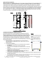
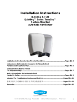
INSTALACIÓN DEL GABINETE:
Realice una abertura en la pared de 362mm (14-1/4") de ancho x 1412mm (55-9/16") de alto. La profundidad mínima
necesaria desde la cara supercial de la pared para la instalación del equipo es 100mm (4"). Permita el espacio
suciente para que el equipo no interera con ningún objeto o característica del baño. Coordine con un ingeniero
mecánico para evitar el contacto con tubos de ventilación y conductos. Si la unidad se proyecta por encima de la
pared, utilice un canal u otro tipo de relleno para eliminar brecha entre la brida del gabinete y acabado cara de pared.
Instale la unidad en la abertura de la pared utilizando cuñas entre el marco y el gabinete en los sitios señalados con
una "S", como se indica en la gura 1, a continuación asegure el equipo utilizando tornillos de chapa (no incluidos)
de 4,2 x 32mm (#8 x 1-1/4"). Suministre servicio eléctrico desde el panel de distribución más cercano a la base de
instalación del secador en conformidad con los códigos eléctricos locales.
CONEXIÓN ELÉCTRICA DEL SECADOR DE MANOS:
Los oricios de entrada para el suministro eléctrico se encuentran en la parte
posterior del gabinete, en la esquina inferior derecha de la base de montaje del
secador y en el lado derecho del gabinete. Los cables que suministran electricidad
al gabinete deben contar con una mayor cantidad de material aislante. El cable
de alimentación en una de estas ubicaciones en el gabinete de la unidad deberá
instalarse utilizando un conducto. Se debe colocar al gabinete una conexión para
tubo pasacables tipo conduit. Se suministra us conector de plástico para ser usado
en caso de ser necesario.
1. Conecte el secador al panel de distribución más cercano. Utilice el
cable requerido por el código eléctrico local, cable 3,31 mm² (Nº 12) de
diámetro o mayor.
2. Instrucciones de cableado:
a. Este aparato está diseñado para ser instalado utilizando una conexión
de cables jos.
b. Un fusible para la desconexión de todos los polos debe
proporcionarse en el cableado jo, en conformidad con las normas de
cableado.
c. Compruebe que el voltaje que se muestra en el secador (placa) sea
compatible con el suministro eléctrico.
d. ADVERTENCIA: ESTE PRODUCTO DEBE SER CONECTADO A
TIERRA (UNIDA A TIERRACONEXIÓN A TIERRA).
e. La instalación y el cableado deben ajustarse a las actuales regulaciones IEE (UK), regulaciones locales o
apropiadas (otros países).
f. Para secadores de 208–240 Voltios: Conecte el cablesuministro de tierra al terminal marcado y los cables
de 208-240 Voltios a los terminales marcados como L (L1) y N (L2).
3. Asegure el cable eléctrico en la abrazadera de soporte de tensión localizada sobre la base de instalación.
Figura 1
Para retirar la cubierta del secador,
retire los dos tornillos ubicados en
la parte
inferior del equipo al igual que
los dos tornillos ubicados en los
costados como se muestra en la
gura 2.
Figura 2
Form No. 38030-69 Revised 6/30/16 © 2016 by Bobrick Washroom Equipment, Inc. Printed in U.S.A.

INSPECCIONE EL FUNCIONAMIENTO DEL SECADOR:
1. Encienda el suministro de energía eléctrica.
2. Coloque las manos por debajo del conducto, dentro de 100mm (4") de la salida de aire.
3. El secador deberá encenderse. A continuación aire caliente saldrá a través de la salida de aire.
4. Retire las manos del alcance del conducto de salida de aire para que el secador se detenga
(aproximadamente 2 segundos). Información del Producto
CONDICIONES GENERALES DE OPERACIÓN:
Los siguientes parámetros operativos ambientales mínimos deberán cumplirse para permitir el correcto
funcionamiento del secador:
1. El equipo funcionará correctamente en el rango operativo de temperatura ambiental previsto, mínimo + 5° C
(41° F) y + 40° C (104° F).
2. El equipo funcionará correctamente dentro de un ambiente de humedad relativa de 50% HR, + 40° C
(104° F). Mayor HR puede ser permitida a temperaturas más bajas. Las medidas serán tomadas por parte del
comprador para evitar los efectos nocivos de la condensación ocasional
3. El equipo funcionará correctamente hasta 2000m (6,560 pies) sobre el nivel del mar.
4. El equipo funcionará en un entorno normal de ocina con un grado 2 de contaminación ambiental.
5. Las fuentes de alimentación en este equipo están diseñadas para operar con voltajes uctuantes de +/- 10%
de lo marcado en la placa de voltaje.
MANTENIMIENTO:
ADVERTENCIA: Las laminaciones del Motor se encuentran "activas".
Apague el suministro eléctrico antes de realizar cualquier mantenimiento
o servicio al secador. El secador no debe utilizarse a menos que la tapa
esté en su lugar. El suminstro eléctrico debe estar apagado a menos que
la cubierta del secador esté colocada.
1. Encienda el suministro de energía eléctrica.
2. Coloque las manos por debajo del conducto, dentro de 100mm (4'')
de la salida de aire.
3. Si se presenta una falla, desconecte el equipo y contacte a un
electricista calicado.
4. No existen piezas con necesidad de mantenimiento dentro del
secador. Devuelva el secador defectuoso al fabricante indicado
a continuación.
NOTA: Si se instala el secador en un lugar donde existe gran cantidad
de polvo y suciedad en el aire, el interior del secador debe ser limpiado
con frecuencia.
INFORMACIÓN DEL PRODUCTO:
Modelo No. B-38030 230V: 208-240 V CA, 3.6-4.0 Amp, 750-950 Vatios, 50/60 Hz, monofásico, Aprobación cULus,
VDE y sello CE esperando aprobación. VDE approved, CE Marked, cUListed, Meets Electrical Safety Requirement:
AS/NZ 60335.2.23:2004.
Peso del producto: 16,5 kg (36,5 Lb).
Lista de Piezas de Repuesto:
38030-2 Ensamblaje de la Puerta (Superior)
38030-26 Ensamblaje de la Puerta (Inferior)
4369-175 Barra de Soporte TowelMate
38030-29 Contenedor de Desechos
38030-25 Cerradura y Llave (Cat 74)
38030-23 Ensamblaje de la placa de montaje para la Cerradura con cinta
38030-36 Ensamblaje del Secador 230V
38030-55 Ensamblaje del Sensor de Activación
38030-40 Ensamblaje de la Boquilla, Izquierda
38030-41 Ensamblaje de la Boquilla, Derecha
Form No. 38030-69 Revised 6/30/16 © 2016 by Bobrick Washroom Equipment, Inc. Printed in U.S.A.
-
 1
1
-
 2
2
-
 3
3
-
 4
4
-
 5
5
-
 6
6
-
 7
7
-
 8
8
-
 9
9


in anderen Sprachen
Verwandte Artikel
-
 Bobrick B-715 Installationsanleitung
-
 Bobrick B-710 Installationsanleitung
-
 Bobrick B-7180 230v Bedienungsanleitung
-
 Bobrick B-7120 230V Bedienungsanleitung
-
 Bobrick B-778 230V Bedienungsanleitung
-
Bobrick B-750 230V Bedienungsanleitung
-
 Bobrick B-7125 Installationsanleitung
-
Bobrick B-7179.MBLK Installationsanleitung
-
Bobrick B-8221 Installationsanleitung


