Bushnell 201440 Benutzerhandbuch
- Kategorie
- Fernglas
- Typ
- Benutzerhandbuch

1
Model: 201440/201441
11-13 ENGLISH

2

3
CONTENTS
English
Français
Español
Deutsch
Italiano
4–15
16–29
30–43
45–57
58–71

4
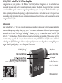
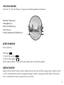
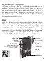
201440/201441 - Bushnell® Tour® Z6™ JOLT - Laser Rangefinder
Congratulations on your purchase of the Bushnell® Tour® Z™ Jolt Laser Rangender, our top of the line laser
rangender for golfers and used by more golf professionals than any other brand. e Tour® Z™ Jolt is a precision
Laser Rangending optical instrument designed to provide many years of enjoyment. is booklet will help you
achieve optimum performance by explaining its adjustments and features as well as how to care for this precise laser
rangending optical instrument. To ensure optimal performance and longevity, please read these instructions before
using your Tour® Z™ Jolt.
INTRODUCTION
Your Bushnell® Tour® Z™ Jolt is an advanced premium laser rangender comprised of Digital Technology and turbo
processors allowing range readings from – yards / – meters, and combines the best of a premium compact
monocular with the new Vivid Display Technology™. Measuring . x x . inches, the -ounce Tour® Z™ Jolt
with E.S.P.™ (Extreme. Speed. Precision.) delivers extremely fast acquisition and incredible ½ Yard accuracy and /
precision from – yards and +/- yard Accuracy from – yards. e Tour® Z™ Jolt features PinSeeker™
technology with JOLT, allowing the golfer to easily and quickly “zero” in on the ag without acquiring background
targets, Superb Optical Quality, & Waterproof Construction.
Vivid Display Technology™6x Magnification
Rubber Armored Metal Housing Adjustable Diopter Setting
100% Waterproof
Posi-Thread™ Battery Door
PinSeeker™ with Jolt Mode
Built-In Accessory Mount
E.S.P.2™ - Extreme. Speed. Precision.
• Gen 2 Turbo Processor Provides Faster Acquisition
• Provides 1/2 Yard Accuracy; 1/10 Precision from 5–125 Yards

5
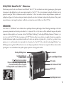
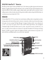
HOW OUR DIGITAL TECHNOLOGY WORKS
e Tour® Z™ Jolt emits invisible, eye safe, infrared energy pulses. e Tour® Z™ Jolt Advanced Digital microprocessor
and ASIC chip (Application-Specic Integrated Circuit) results in instantaneous and accurate readings every time.
Sophisticated digital technology instantaneously calculates distances by measuring the time it takes for each pulse to
travel from the rangender, to the target, and back.
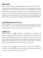
RANGING ACCURACY
e ranging accuracy of the Tour® Z™ Jolt is plus or minus one yard / meter under most circumstances. e maximum
range of the instrument depends on the reectivity of the target. e maximum distance for most objects is yards
/ meters while for highly reective objects the maximum is yards / meters.
Note: You will get both longer and shorter maximum distances depending on the reflective properties of the particular target and the environmental conditions
at the time the distance of an object is being measured. The color, surface finish, size and shape of the target all affect reflectivity and range. The brighter
the color, the longer the range. Red is highly reflective, for example, and allows longer ranges than the color black, which is the least reflective color. A shiny
finish provides more range than a dull one. A small target is more difficult to range than a larger target. The angle to the target also has an effect. Shooting
to a target at a 90 degree angle (where the target surface is perpendicular to the flight path of the emitted energy pulses) provides good range while a steep
angle on the other hand, provides limited ranging. In addition, lighting conditions (e.g. the amount of sunlight) will affect the ranging capabilities of the
unit. The less light (e.g. overcast skies) the farther the unit’s maximum range will be. Conversely, very sunny days will decrease the unit’s maximum range.
E.S.P.2™ (Extreme. Speed. Precision. 2nd generation), our advanced second generation ranging technology, provides the fastest, most
accurate ranging measurement based on target conditions. The laser analyzes multiple individual measurements to the target and calculates and
displays the best possible result. Target variations such as reflectance, shape and color can affect the accuracy of a laser measurement, but E.S.P.2™
automatically assesses the conditions and improves the measurement up to 1/2 Yard Accuracy whenever possible from 5–125 yards. When this occurs,
display readout precision will be refined to 1/10th yard.

6
GETTING STARTED
OPERATIONAL SUMMARY
While looking through the Tour® Z™ Jolt, depress the power button once to activate the Vivid Display. Place the
aiming circle (located in the center of the eld of view) upon a target at least yards away, depress and hold the power
button down until the range reading is displayed near the bottom of the in-view display. Crosshairs surrounding the
aiming circle indicate that the laser is being transmitted. Once a range has been acquired, you can release the power
button. e crosshairs surrounding the aiming circle will disappear once the power button has been released (i.e. the
laser is no longer being transmitted).
Note: Once activated, the display will remain active and display the last distance measurement for 7 seconds. You can depress the power button again at any
time to distance to a new target. As with any laser device, it is not recommended to directly view the emissions for long periods of time with magnified lenses.
The maximum time the laser is transmitted (fired) is 7 seconds. To re-fire, press the button down again.
ADJUSTING THE EYEPIECE
Your Tour® Z™ Jolt is constructed with a fold-down eyepiece designed for comfort and to exclude extraneous light.
e Tour® Z™ Jolt provides extra-long eye-relief. If you wear glasses, make sure the eyecup is in the down position
as this will bring your eye closer the eyepiece lens allowing you to see a full eld of view. e Tour® Z™ Jolt is also
equipped with an adjustable eyepiece (+/- Diopter Adjustment) that allows one to focus the VDT™ display relative
to the image. Simply rotate the eyepiece until the red display is in focus.

7
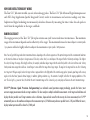
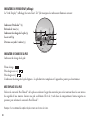
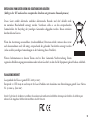
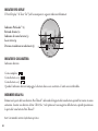
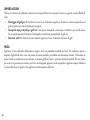
VIVID DISPLAY INDICATORS
Your Tour® Z™ Jolt Vivid Display™ incorporates the following illuminated indicators:
PinSeeker™ Indicator ()
Aiming Reticle ()
Battery Life Indicator ()
Active Laser ()
Distance Displayed in Yards/Meters ()
4
1
35
2
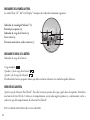
BATTERY LIFE INDICATOR
Battery Indicator:
Full charge
/ battery life remaining
/ battery Life remaining
Battery Indicator Blinks - Battery needs to be replaced and unit will not be operable.
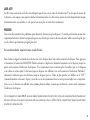
INSERTING THE BATTERY
Remove the Posi-read™ battery door by lifting the battery door tab and then rotating counter clockwise. Insert
a CR2 3-volt lithium battery into the compartment negative end rst, then replace the Posi-read™ battery door.
Note: It is recommended that the battery be replaced at least once every 6 months.
103
PinSeeker beyond E.S.P range— 20196, 205107, 205108
PinSeeker & E.S.P—201960
PinSeeker & E.S.P “Play-As”PinSeeker Slope & E.S.P

8
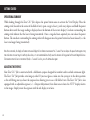
ACTIVE LASER
Crosshairs surrounding the aiming circle indicate that the laser is being transmitted. Once a range has been acquired,
you can release the power button. e crosshairs surrounding the circle will disappear once the power button has been
released (i.e. the laser is no longer being transmitted).
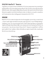
PINSEEKER™
Ever have trouble getting distance to the ag? is advanced mode allows easy acquisition of the ag without
inadvertently getting distances to background targets (i.e. trees) that have stronger signal strength.
For ease of use, the device will always be in PinSeeker™ Mode.
To use, align the aiming circle reticle onto the ag that you want distance to. Next, press and hold the POWER button
and move the laser slowly over the ag or desired object until a circle surrounds the ag indicator. If the laser beam
recognized more than one object (i.e. ag and background trees), distance of the ag will be displayed and a circle will
surround the PinSeeker™ indicator informing the user that distance to the ag (i.e. closer object) is being displayed
in the VDT™ (as seen below). ere may be times when only the laser beam only sees one object in its path. In this
case, the distance will be displayed, but because more than one object was not acquired, a circle will not surround the
ag indicator.
Tip: While pressing the POWER button, you can move the device slowly from object to object and intentionally force the laser to hit multiple objects to ensure that
you are only displaying the closest of the objects recognized by the laser. Once the device has shut off, the unit will always default back to the last mode used.

9
PINSEEKER™ WITH SLOPE +/-™
e advanced patented SLOPE mode is available only on model . is model features a built-in accelerometer-
based inclinometer that digitally displays the exact slope angle from - to + degrees of elevation and is +/- . degree
accurate. e Slope +/-™ mode will automatically compute an angle compensated range based upon distance and slope
angle determined by the laser rangender and built-in inclinometer. is data is then combined with internal algorithmic
formulas dealing with average club use and ball trajectories. e angle compensated range provides direction on how to
play the shot (i.e. add distance if an incline, subtract distance if a decline).
ACTIVATING SLOPE MODE (Model 201441 only)
e Tour® Z™ Jolt Slope +/-™ was especially designed with golfers in mind. e SLOPE mode allows you to display the
angle and “Play-As” distance. To activate or deactivate this mode, press the POWER button once to turn the unit ON.
en while looking through the eyepiece, press the MODE button and quickly release.
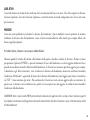
HOW TO USE SLOPE +/-™
Once in this mode, you will see a “ ° ” in the eld of view informing you that you are in the Slope +/- Mode. Press
the POWER button to obtain distance to the ag or other objects. Once the range is displayed, continue to hold the
POWER button down for approximately seconds while holding the aiming circle on the ag and keeping the unit
as steady as possible so as to allow the inclinometer enough time to measure slope. en release the POWER button.
Once you have released the power button, a degree of angle and compensated range will be displayed beneath the
standard distance as seen below.
In this example, the true distance is yards, slope is + degrees, and the compensated range is yards. e “ ”
symbol means “Play-As”, so instead of playing as yards, “play-as” yards.

10
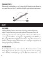
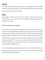
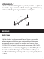
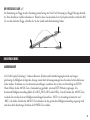
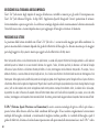
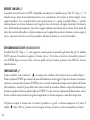
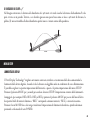
THE ADVANTAGE OF SLOPE +/-™
e distance to ag A in the drawing below is yards. It is also yards to ag B although it is on a slope. However, if you
were to play this hole as yards, the ball (X) would fall short of the hole/ag because you did not take slope into account.
DISPLAY BRIGHTNESS
Vivid Display Technology™ dramatically improves contrast, clarity and light transmission while increasing
brightness of the digital readout, making distance readings legible in low light environments. ere are four
intensity settings to choose from and this is the rst setting within the SETUP menu. Press the MODE button for
seconds to get into the SETUP menu. e existing brightness setting will be ashing (i.e. BRT, BRT, BRT, or
BRT), pressing the MODE button will toggle between the four brightness settings. “BRT” is the lowest intensity
while “BRT ” is the brightest. Simply press the MODE button until the desired brightness setting is displayed and
select by pressing and releasing the POWER button.
UNIT OF MEASURE OPTIONS
e Tour® Z™ Jolt can be used to measure distances in yards or meters. e unit of measure indicators are located in
the lower right portion of the VDT™. ere are two measuring settings to choose from and this is the second setting
within the SETUP menu. Look through the eyepiece, depress the “MODE” button (“B” Button on side of device)
MENU SETUP
162 YARDS
162 YARDS
X
4°

11
and hold it down for approximately seconds to get into the SETUP menu. Depressing the MODE button will toggle
through the brightness settings. If you are changing from yards to meters, a change in unit of measure will be indicated
by the illumination of the M for meter indicator while the Y for Yard indicator is turned o. If you are changing from
meters to yards, the opposite will occur. e Tour® Z™ Jolt will return to the last unit of measure setting used each
time the unit is turned on.
ENABLING JOLT FEATURE
e Tour® Z™ Jolt features PinSeeker™ technology with JOLT, allowing the golfer to easily and quickly “zero” in on
the ag without acquiring background targets. e Jolt feature provides a short vibration to indicate when Pinseeker
has triggered. is Jolt feature may be disabled in the setup menu. Holding the mode button will put the unit into the
setup mode. e Jolt enable/disable is the third option, after the brightness setting and yard/meter selection. Pressing
the re button when the display indicates “JLT on” will enable the Jolt feature. Pressing the re button when the
display indicates “JLT o: will disable the Jolt feature. In the settings mode the mode button toggles between “JLT
on” and “JLT o”.
ACCESSORY MOUNT
Molded into the bottom of the product is a threaded accessory mount that will allow you to attach the following Bushnell®
Golf Accessories:
• Golf Cart Mount: Attaches the rangender to your golf cart for easy access. Quick release clamp attaches to golf cart
and can be easily removed afterwards.
• Push/Pull Cart Monopod: Steady your hand with this telescoping monopod. Simply attach rangender to the
monopod and insert into cart umbrella holder.
• 360R Retractor: Attaches the rangender to your golf bag for easy access while walking the course.

12
CLEANING
Gently blow away any dust or debris on the lenses (or use a soft lens brush). To remove dirt or ngerprints, clean with a soft
cotton cloth, rubbing in a circular motion. Use of a coarse cloth or unnecessary rubbing may scratch the lens surface and
eventually cause permanent damage. For a more thorough cleaning, photographic lens tissue and photographic-type lens
cleaning uid or isopropyl alcohol may be used. Always apply the uid to the cleaning cloth – never directly on the lens.
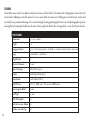
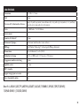
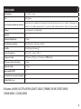
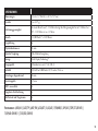
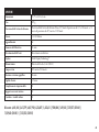
SPECIFICATIONS
Dimensions . x x . inches
Weight 8 oz.
Ranging Accuracy Up to ½ yard accuracy from – Yards, +/- yards accuracy from – yards
Range – Yards / – Meters
Magnification 6x
Objective Diameter 21 mm
Optical Coatings Fully Multi-Coated
Display Vivid Display Technology™
Power Source 3-volt lithium (CR-2)
Field Of View 393 ft. @ 1000 yards / 119 meters at 1000 meters
Extra Long Eye Relief 16 mm
Exit Pupil 3.5 mm
100% Waterproof Yes
Built-In Accessory Mount Yes
Includes case and strap Yes

13
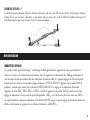
TWO-YEAR LIMITED WARRANTY
Your Bushnell® laser rangender is warranted to be free of defects in materials and workmanship for two years after the date of purchase. In the event of a
defect under this warranty, we will, at our option, repair or replace the product, provided that you return the product postage prepaid. is warranty does
not cover damages caused by misuse, improper handling, installation, or maintenance provided by someone other than a Bushnell® Authorized Service
Department.
Any return made under this warranty must be accompanied by the items listed below:
. A check/money order in the amount of . to cover the cost of postage and handling
. Name and address for product return
. An explanation of the defect
. Proof of Date Purchased
. Product should be well packed in a sturdy outside shipping carton, to prevent damage in transit, with returnpostage prepaid to the address listed below:
IN U.S.A. Send To: IN CANADA Send To:
Bushnell® Outdoor Products Bushnell® Outdoor Products
Attn.: Repairs Attn.: Repairs
Cody Great Gulf Drive, Unit B
Overland Park, Kansas Vaughan, Ontario LK W
For products purchased outside the United States or Canada please contact your local dealer for applicable warranty information.
In Europe you may also contact Bushnell® at:
Bushnell Germany GmbH
European Service Centre
Mathias-Brüggen-Str.
D- Köln
GERMANY
Tél: + -
Fax: + -
is warranty gives you specic legal rights.
You may have other rights which vary from country to country.
© Bushnell® Outdoor Products

14
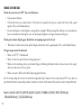
TROUBLE SHOOTING TABLE
If unit does not turn on/ VDT™ does not illuminate:
• Depress power button.
• Check and if necessary, replace battery. If unit does not respond to key presses, replace the battery with a good
quality CR -volt Lithium battery.
• Ensure the display is on the brightest setting while in sunlight. While pressing Power Button, cover the objective
lenses to determine if the display is on. See the display brightness setting instructions on Page .
If unit powers down (display goes blank when attempting to power the laser):
• e battery is either weak or low quality. Replace the battery with a good quality CR -volt Lithium battery.
If target range cannot be obtained:
• Make sure VDT™ is illuminated.
• Make sure that the power button is being depressed.
• Make sure that nothing, such as your hand or nger, is blocking the objective lenses (lenses closest to the target)
that emit and receive the laser pulses.
• Make sure unit is held steady while depressing power button.
Note: The last range reading does not need to be cleared before ranging another target. Simply aim at the new target using the VDT™’s reticle, depress the
power button and hold until new range reading is displayed. Specifications, instructions, and the operation of these products are subject to change without notice.
Patent #’s: 6,445,444 | 5,612,779 | 6,057,910 | 6,226,077 | 5,652,651 | 7,920,080 | 7,619,548 | 7,239,377 (201441 only) |
7,859,650 (201441 only) | 7,535,553 (201441 only)

15
FCC NOTE
This equipment has been tested and found to comply with the limits for a Class B digital device, pursuant to Part
15 of the FCC Rules. These limits are designed to provide reasonable protection against harmful interference in a
residential installation. This equipment generates, uses and can radiate radio frequency energy and, if not installed
and used in accordance with the instructions, may cause harmful interference to radio communications. However,
there is no guarantee that interference will not occur in a particular installation. If this equipment does cause harmful
interference to radio or television reception, which can be determined by turning the equipment off and on, the user
is encouraged to try to correct the interference by one or more of the following measures:
• Reorient or relocate the receiving antenna.
• Increase the separation between the equipment and receiver.
• Connect the equipment into an outlet on a circuit different from that to which the receiver is connected.
• Consult the dealer or an experienced radio/TV technician for help.
Shielded interface cable must be used with the equipment in order to comply with the limits for a digital device
pursuant to Subpart B of Part 15 of FCC Rules. Specifications and designs are subject to change without any notice
or obligation on the part of the manufacturer.
FDA SAFETY
Class laser product in accordance with IEC -:.
Complies with CFR . and . for laser products except for deviations pursuant to Laser Notice No. , dated
June , .
Caution: There are no user controls, adjustments or procedures. Performance of procedures other than those specified herein may result in access to invisible
laser light.

16
Model: 201440/201441
LIT. #: 11-13 FRANÇAIS

17
201440/201441 - Bushnell® Tour® Z6™ Jolt - Télémètre Laser
Félicitations pour l’achat de votre Télémètre Laser Bushnell® Tour® Z™ Jolt, un télémètre laser haut de gamme pour golfeurs parmi
les marques les plus plébiscitées par les joueurs professionnels. Le Tour® Z™ Jolt est un instrument optique de télémétrie laser de
précision conçu pour orir de nombreuses années de satisfaction. Ce livret vous aidera à obtenir une performance optimale car il
explique les réglages et les fonctions ainsi que la manière de prendre soin de cet instrument optique à laser de précision. Pour garantir
une performance et une longévité optimales, veuillez lire ces instructions avant d’utiliser votre Tour® Z™ Jolt.
INTRODUCTION
Votre Tour® Z™ Jolt Bushnell® est un télémètre laser sophistiqué de haute qualité équipé d’une Technologie numérique et de turbo
processeurs permettant une lecture de portée allant de à yards / de à mètres et allie le meilleur d’une paire de jumelles
compactes de haute qualité avec le nouveau système Vivid Display Technology™ (technologie d’achage lumineux). Mesurant , x
, x , cm, le Tour® Z™ Jolt de grammes avec E.S.P.™ (Précision d’une vitesse extrême) est capable de fournir une acquisition
de cible extrêmement rapide, une précision incroyable au ½ mètre, une précision à /ème de à yards (,– mètres) et une
précision à +/- yard ( cm) de à yards (– mètres). Le Tour® Z™ Jolt est doté de la technologie PinSeeker™ avec
JOLT, qui permet au golfeur d’eectuer la mise à zéro sur le drapeau rapidement et facilement sans acquérir la distance d’autres cibles
plus éloignées, tout en bénéciant d’une qualité optique supérieure et d’un appareil étanche.
Support intégré pour accessoire
Mode PinSeeker™
Cache de la batterie Posi-Thread™
100 % étanches
Mise au point/Réglage de la dioptrie
Grossissement x 6Technologie d’affichage lumineux
Construction métallique avec
revêtement caoutchouc
E.S.P.™ (Précision d’une vitesse extrêmen)
• Processeur turbo qui assure une acquisition plus rapide
• Fournit une exactitude de 0,45 m et une précision
d’affichage de 0,09 m sur une fourchette de 4,5 à 114 m

18
FONCTIONNEMENT DE NOTRE TECHNOLOGIE NUMÉRIQUE
Le Tour® Z™ Jolt émet des pulsions d’énergie infrarouge invisibles, et sans danger pour les yeux. Le microprocesseur
numérique de pointe et la puce ASIC (circuit intégré d’application spécique) du Tour® Z™ Jolt permettent à
chaque fois des relevés de distance instantanés et précis. La technologie numérique sophistiquée calcule les distances
instantanément en mesurant le temps nécessaire à chaque pulsion pour aller du télémètre à la cible et revenir.
PRÉCISION DE L’ÉVALUATION DES DISTANCES
La précision de l’évaluation des distances du Tour® Z™ Jolt est de plus ou moins un mètre/yard dans la plupart des cas. La
plage d’évaluation maximum de l’appareil dépend de la réectivité de la cible. La distance maximum pour la plupart des
objets est de yards / mètres, alors que pour les objets très rééchissants elle peut atteindre yards / mètres.
Remarque : Vous obtiendrez à la fois des distances maximales plus longues et plus courtes selon les propriétés de réflectivité d’une cible particulière
et les conditions environnementales au moment de la mesure de distance d’un objet. La couleur, le fini de surface, la taille et la forme de la cible
affectent la réflectivité et la portée. Plus la couleur est vive, plus longue est la plage de mesure. Le rouge, par exemple, est très réfléchissant et permet
des plages de mesure plus longues que la couleur noire, qui est la couleur la moins réfléchissante. Un fini brillant permet une plage de mesure plus
longue qu’un fini mat. Une cible de petite taille est plus difficile à évaluer qu’une plus grande cible. L’angle de la cible a également un effet. Viser
une cible à un angle de 90 degrés (lorsque la surface de la cible est perpendiculaire au trajet des pulsions d’énergie émises) permet une longue
plage de mesure alors que viser une cible à angle aigu, réduit la mesure. De plus, les conditions d’éclairage (quantité de lumière solaire) affecteront
également les capacités de mesure de l’appareil. Moins il y a de lumière (par ex. ciel couvert), plus la plage de mesure maximale de l’appareil s’allonge.
Inversement, les journées très ensoleillées réduiront la plage de mesure maximale de l’appareil.
L’E.S.P.2™ (Extreme. Speed. Precision. 2nd generation), notre technologie deuxième génération avancée de prise de mesures, vous offre les mesures
les plus rapides et précises compte tenu des conditions de la cible. Le laser analyse de multiples mesures individuelles de la cible, calcule et affiche
le meilleur résultat possible. Les variations de la cible, telles que la réflectivité, la forme et la couleur peuvent affecter la précision d’une mesure au
laser, mais l’E.S.P.2™ évalue automatiquement les conditions et améliore la mesure avec une précision à ½ yard (0,45 mètre) chaque fois que cela est
possible de 5 à 125 yards (4,5 à 114 mètres). Dans ce cas, la précision des mesures affichées est améliorée jusqu’à 1/10 de yard.

19
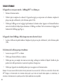
POUR COMMENCER
RÉSUMÉ DU FONCTIONNEMENT DE L’APPAREIL
Tout en regardant dans le Tour® Z™ Jolt, appuyez une fois sur le bouton marche pour activer le Vivid Display. Placez
le cercle de visée (situé au centre du champ de vision) sur une cible se trouvant à au moins mètres, maintenez le
bouton de marche enfoncé jusqu’à ce que la mesure de distance soit achée près du bas de l’achage. Les ls croisés
autour du cercle de visée indiquent que le laser est en cours de transmission. Une fois que la mesure de la distance a
été acquise, vous pouvez relâcher le bouton marche. Les ls croisés autour du cercle de visée disparaîtront lorsque le
bouton marche sera relâché (c.-à-d. que le laser n’est plus en cours de transmission).
Remarque : Une fois activé, l’affichage restera actif et indiquera la dernière distance mesurée pendant 7 secondes. Vous pouvez appuyer de nouveau sur le
bouton marche à tout moment pour obtenir la distance d’une nouvelle cible. Comme avec tout dispositif à laser, il est déconseillé de regarder directement les
émissions pendant des périodes prolongées avec des lentilles grossissantes. La période maximale de la transmission (envoi) des rayons laser est de 7 secondes.
Pour viser à nouveau, appuyez sur le bouton.
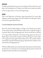
RÉGLAGE DE L’OCULAIRE
Votre Tour® Z™ Jolt est doté d’un oculaire rabattable conçu pour des raisons de confort et pour éliminer la lumière
superue. Le Tour® Z™ Jolt permet un dégagement oculaire extra long. Si vous portez des lunettes, vériez que
l’œilleton est abaissé car cette position permet à l’œil d’être plus près de la lentille vous permettant de voir la largeur de
champ maximale. Le Tour® Z™ Jolt est également équipé d’un oculaire réglable (réglage à +/- dioptres) qui permet
une mise au point de l’achage VDT™ par rapport à l’image. Tournez simplement l’oculaire jusqu’à la mise au point
sur l’achage rouge.

20
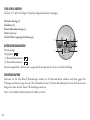
INDICATEURS DU VIVID DISPLAY (affichage)
Le Vivid Display™ (achage) de votre Tour® Z™ Jolt incorpore les indicateurs illuminés suivants:
Indicateur PinSeeker™ ()
Réticule de visée ()
Indicateur de charge de la pile ()
Laser actif ()
Distance en yards / mètres ()
INDICATEUR DE CHARGE DE LA PILE
Indicateur de charge de la pile:
Pleine charge
Pile chargée aux /
Pile chargée à /
L’indicateur de charge de la pile clignote - La pile doit être remplacée et l’appareil ne pourra pas fonctionner.
MISE EN PLACE DE LA PILE
Enlevez le couvercle Posi-read™ de la pile en soulevant l’ergot du couvercle puis en le tournant dans le sens inverse
des aiguilles d’une montre. Insérez une pile au lithium CR-2 de 3 volts dans le compartiment, borne négative en
premier, puis refermez le couvercle Posi-read™.
Remarque: Il est recommandé de remplacer la pile au moins une fois tous les 6 mois.
103
PinSeeker beyond E.S.P range— 20196, 205107, 205108
PinSeeker & E.S.P—201960
PinSeeker & E.S.P “Play-As”PinSeeker Slope & E.S.P
3
4
1
5
2
Seite wird geladen ...
Seite wird geladen ...
Seite wird geladen ...
Seite wird geladen ...
Seite wird geladen ...
Seite wird geladen ...
Seite wird geladen ...
Seite wird geladen ...
Seite wird geladen ...
Seite wird geladen ...
Seite wird geladen ...
Seite wird geladen ...
Seite wird geladen ...
Seite wird geladen ...
Seite wird geladen ...
Seite wird geladen ...
Seite wird geladen ...
Seite wird geladen ...
Seite wird geladen ...
Seite wird geladen ...
Seite wird geladen ...
Seite wird geladen ...
Seite wird geladen ...
Seite wird geladen ...
Seite wird geladen ...
Seite wird geladen ...
Seite wird geladen ...
Seite wird geladen ...
Seite wird geladen ...
Seite wird geladen ...
Seite wird geladen ...
Seite wird geladen ...
Seite wird geladen ...
Seite wird geladen ...
Seite wird geladen ...
Seite wird geladen ...
Seite wird geladen ...
Seite wird geladen ...
Seite wird geladen ...
Seite wird geladen ...
Seite wird geladen ...
Seite wird geladen ...
Seite wird geladen ...
Seite wird geladen ...
Seite wird geladen ...
Seite wird geladen ...
Seite wird geladen ...
Seite wird geladen ...
Seite wird geladen ...
Seite wird geladen ...
Seite wird geladen ...
Seite wird geladen ...
-
 1
1
-
 2
2
-
 3
3
-
 4
4
-
 5
5
-
 6
6
-
 7
7
-
 8
8
-
 9
9
-
 10
10
-
 11
11
-
 12
12
-
 13
13
-
 14
14
-
 15
15
-
 16
16
-
 17
17
-
 18
18
-
 19
19
-
 20
20
-
 21
21
-
 22
22
-
 23
23
-
 24
24
-
 25
25
-
 26
26
-
 27
27
-
 28
28
-
 29
29
-
 30
30
-
 31
31
-
 32
32
-
 33
33
-
 34
34
-
 35
35
-
 36
36
-
 37
37
-
 38
38
-
 39
39
-
 40
40
-
 41
41
-
 42
42
-
 43
43
-
 44
44
-
 45
45
-
 46
46
-
 47
47
-
 48
48
-
 49
49
-
 50
50
-
 51
51
-
 52
52
-
 53
53
-
 54
54
-
 55
55
-
 56
56
-
 57
57
-
 58
58
-
 59
59
-
 60
60
-
 61
61
-
 62
62
-
 63
63
-
 64
64
-
 65
65
-
 66
66
-
 67
67
-
 68
68
-
 69
69
-
 70
70
-
 71
71
-
 72
72


Bushnell 201440 Benutzerhandbuch
- Kategorie
- Fernglas
- Typ
- Benutzerhandbuch
in anderen Sprachen
- English: Bushnell 201440 User manual
- français: Bushnell 201440 Manuel utilisateur
- español: Bushnell 201440 Manual de usuario
- italiano: Bushnell 201440 Manuale utente
Verwandte Artikel
-
Bushnell Pro X7 Jolt 201400 Benutzerhandbuch
-
Bushnell Tour V3 Slope Benutzerhandbuch
-
Bushnell TOUR V4 SLOPE EDITION Benutzerhandbuch
-
-
-
Bushnell 205107 Benutzerhandbuch
-
Bushnell GOLF 201835 HYBRID Laser/GPS Rangefinder Benutzerhandbuch
-