
Bedienungsanleitung
Operation Manual
Entsorgen Sie dieses Produkt nicht über den (unsortierten)
Hausmüll, sondern führen Sie es der Wiederverwertung zu.
Do not dispose of this product through (unsorted) domestic
waste, supply it to recycling instead.
Subject to change without prior notice. No liability for mistakes and prin-
ting errors.
You will find the latest version of the manual on the Viessmann website using
the item number.
Änderungen vorbehalten. Keine Haftung für Druckfehler und Irrtümer.
Die aktuelle Version der Anleitung finden Sie auf der Viessmann Homepage
unter der Artikelnummer.
Viessmann
Modelltec
hnik GmbH
Bahnhofstraße 2a
D - 35116 Hatzfeld-Reddighausen
+49 6452 9340-0
www.viessmann-modell.de
Made in Europe
FR
Points de collecte sur www.quefairedemesdechets.fr
À DÉPOSER
EN MAGASIN À DÉPOSER
EN DÉCHÈTERIE
OU
Cet modéle
se recycle
FR
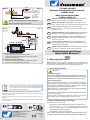
TIPP: Powermodul, Art. 5215
- Verhindert Flackern bei Wechselstrom.
- Annähernd doppelte Helligkeit gegenüber reinem
Wechselstrombetrieb.
HINT: Power module, item 5215
- Offers flicker-free lighting when using AC power.
- Nearly double brightness is possible.
89374
Stand 01/sw
03/2023
Ho/Kf
Sekundär
0-10-16 V~
16 V
Primär
230 V~
Gefertigt nach
VDE 0570
EN 61558
Lichttransformator
5200
Nur für trockene Räume
Primär 230 V 50 - 60 Hz
Sekundär max. 3,25 A52 VA
ta 25°CIP 40
10 V
0 V
viessmann
Powermodul
5215
T
E
ge bn
Braune Massebuchsen
nicht koppeln !
max. 24 V~
rt bn
zu den Decodern
5215
gelb/
braun / brown
16 V~
z. B./e. g. 5200
yellow
16 V~
Modellbauartikel, kein Spielzeug! Nicht geeignet für
Kinder unter 14 Jahren! Anleitung aufbewahren!
Model building item, not a toy! Not suitable for chil-
dren under the age of 14 years! Keep these instructions!
Ceci n’est pas un jouet. Ne convient pas aux
enfants de moins de 14 ans ! Conservez cette notice
d’instructions!
Modelbouwartikel, geen speelgoed! Niet geschikt voor
kinderen onder 14 jaar! Gebruiksaanwijzing bewaren!
Articolo di modellismo, non è un giocattolo! Non
adatto a bambini al di sotto dei 14 anni! Conservare
istruzioni per l’uso!
Artículo para modelismo. No es un juguete! No
recomendado para menores de 14 años! Conserva las
instrucciones de servicio!
Não é um brinquedo! Não aconselhável para menores
de 14 anos. Conservar o manual de instruções.
DE
EN
FR
NL
IT
ES
TT 6923, N 6623
Bausatz Peitschenleuchte doppelt,
2 LEDs weiß
Whip street light double,
2 LEDs white, kit
Abb. 5 Fig. 5
PT
1. Wichtige Hinweise
Bitte lesen Sie vor der ersten Anwendung des Produktes bzw.
dessen Einbau diese Bedienungsanleitung aufmerksam durch
und bewahren Sie diese auf. Sie ist Teil des Produktes.
1.1 Sicherheitshinweise
Vorsicht:
Verletzungsgefahr!
Aufgrund der detaillierten Abbildung des Originals bzw. der vorgese-
henen Verwendung kann das Produkt Spitzen, Kanten und abbruch-
gefährdete Teile aufweisen. Für die Montage sind Werkzeuge nötig.
Stromschlaggefahr!
Die Anschlussdrähte niemals in eine Steckdose einführen!
Verwendetes Versorgungsgerät (Transformator, Netzteil)
regelmäßig auf Schäden überprüfen. Bei Schäden am Ver
-
sorgungsgerät dieses keinesfalls benutzen!
Alle Anschluss- und Montagearbeiten nur bei abgeschalteter
Betriebsspannung durchführen!
Ausschließlich nach VDE/EN gefertigte Modellbahntransfor-
matoren verwenden!
Stromquellen unbedingt so absichern, dass es bei einem
Kurzschluss nicht zum Kabelbrand kommen kann.
1.2 Das Produkt richtig verwenden
Dieses Produkt ist bestimmt:
- Zum Einbau in Modelleisenbahnanlagen und Dioramen.
- Zum Anschluss an einen Modellbahntransformator
(z. B. Art. 5200) bzw. an eine Modellbahnsteuerung mit
zugelassener Betriebsspannung.
- Zum Betrieb in trockenen Räumen.
Jeder darüber hinausgehende Gebrauch gilt als nicht bestimmungs-
gemäß. Für daraus resultierende Schäden haftet der Hersteller nicht.
DE
16
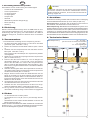
Diode
diode
Widerstand
resistor
LED-Leuchte
LED lamp
schwarz/black
Diode und Widerstand nicht abschneiden!
Never cut o diode and resistor!
Diode
diode
Widerstand
resistor
Abb. 4 Fig. 4
schwarz/black
+
10 – 16 V AC ~
14 – 24 V DC =
13 – 24 V
Digitalsignal
digital signal
–
(mit und ohne 5215 Powermodul)
(with and without 5215 power module)

1.3 Packungsinhalt überprüfen
Kontrollieren Sie den Lieferumfang auf Vollständigkeit:
- 2 LEDs mit Anschlusskabeln
- 2 Schrumpfschläuche
- 2 Lampenschirme
- 2 Lampengläser
- Lampenmast
- Steckfuß
- Widerstand (mehrere farbige Ringe)
- Diode (ein Ring)
- Anleitung
2. Einleitung
Dieser Leuchtenbausatz erzeugt durch die SMD-LEDs ein zum
Lampenmodell passendes Licht. Stromaufnahme und Wärme-
entwicklung sind sehr gering. Die Lebensdauer der LEDs ist
praktisch unbegrenzt, sodass ein Wechsel des Leuchtmittels
entfällt.
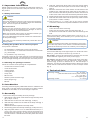
3. Zusammenbau
- Leuchtenbausatz vorsichtig aus der Verpackung nehmen.
1. Die Kabel der beiden LEDs werden von oben durch den Mast
geschoben (Abb. 3 Schritte 1 und 2).
2. Danach den Steckfuß auf die Kabel schieben (Abb. 3 Schritt
3).
3. Schieben Sie die Lampenschirme über die LEDs auf den
Mast (Abb. 3 Schritte 4 und 5).
Dann wird der LED-Leuchtkörper im Lampenschirm platziert
und eingeklebt.
4. Klipsen Sie nun jeweils das Lampenglas auf den Lampenschirm
(Abb. 3 Schritte 6 und 7).
5. Isolieren Sie das braune Kabel ca. 2 cm ab. Biegen Sie
den blanken Draht (ca. 1 cm) um 180°, bis er sich berührt.
Führen Sie den Draht von unten in den Lampenmast ein
(Abb. 3 Schritt 8). Der Messingmast dient somit als 2. Leiter.
Das braune und gelbe Kabel müssen unterhalb des Mastes
verdrillt werden.
6. Schieben Sie das gelbe Stück Schrumpfschlauch auf die bei-
den gelben Kabel und das schwarze Stück Schrumpfschlauch
auf das braune Kabel (Abb. 3 Schritt 9).
7. Biegen Sie den kurzen Draht des Widerstandes und der
Diode in der Mitte um 90 Grad. Wickeln Sie die blanken
Kabelenden der gelben Kabel um das Drahtstück direkt un-
terhalb des Widerstandes sowie das Kabelende des braunen
Kabels um das der Diode.
8. Anschließend biegen Sie das senkrecht hochstehende Ende
des Widerstandes sowie der Diode um.
9. Schieben Sie den Schrumpfschlauch auf die zuvor herge
-
stellte Kontaktstelle (Kabel + Widerstand oder Diode).
10. Kurz (!) erhitzen, etwa mit einer Heißluftpistole. Schon ist die
dauerhafte Verbindung fertig! Vorsicht Verbrennungsgefahr!
4. Einbau
- Vor dem Einbau auf Funktion prüfen.
- Am Einbauort ein Loch (Ø 3,5 mm) zur Montage bohren
(Abb. 1).
- Steckfuß der Leuchte mit den Anschlusskabeln von oben in die
Bohrung stecken (Abb. 2).
Lassen Sie beim Anschließen der Kabel unterhalb der Leuchte eine
Schleife von ca. 2 – 3 cm Länge, damit Sie die Leuchte bei evtl. Arbei-
ten aus der Montagebohrung ziehen und umlegen können.
DE
3
2
Vorsicht:
Widerstand und Diode an den Enden der Anschlussdrähte
sind für die Funktion erforderlich. Widerstände nicht mit
Isolationsmaterial umhüllen, da sonst keine ausreichende
Kühlung möglich ist!
5. Anschluss
Schließen Sie die fertig montierte LED-Leuchte an den Lichtausgang
eines Modellbahntransformators (z. B. Art. 5200) an (Abb. 4/5).
Gleichspannung: Verbinden Sie die Diode mit dem Plus-Pol
des Netzteils, den Widerstand mit dem Minus-Pol.
Wechselspannung: Bei Betrieb mit Wechselspannung kann es zu
leichtem Flackern kommen. Daher empfehlen wir den Betrieb mit dem
Viessmann-Powermodul, Art. 5215 (Abb. 5). Ein Powermodul ist aus-
reichend für ca. 100 LED-Leuchten oder -Strahler. Verbinden Sie das
Anschlusskabel mit der Diode mit der braunen Ausgangsbuchse, das
Anschlusskabel mit dem Widerstand mit der roten Anschlussbuchse.
6. Technische Daten
Betriebsspannung: 10 – 16 V AC ~
(mit und ohne Art. 5215 Powermodul)
14 – 24 V DC =
13 – 24 V Digitalsignal
Stromaufnahme: ca. 10 mA
Abb. 3 Fig. 3
Abb. 1 Abb. 2
Ø 3,5 mm
Fig. 1 Fig. 2

EN
1. Important information
Please read this manual completely and attentively before us-
ing the product for the first time. Keep this manual. It is part of
the product.
1.1 Safety instructions
Caution:
Risk of injury!
Due to the detailed reproduction of the original and the intend-
ed use, this product can have peaks, edges and breakable
parts. Tools are required for installation.
Electrical hazard!
Never put the connecting wires into a power socket!
Regularly examine the transformer for damage. In case of
any damage, do not use the transformer!
Make sure that the power supply is switched off when you
mount the device and connect the cables!
Only use VDE/EN tested special model train transformers
for the power supply!
The power sources must be protected to prevent the risk of
burning cables.
1.2 Using the product for its correct purpose
This product is intended:
- For installation in model train layouts and dioramas.
- For connection to an authorized model train transformer
(e. g. item 5200).
- For operation in dry rooms only.
Using the product for any other purpose is not approved and is
considered inappropriate. The manufacturer is not responsible
for any damage resulting from the improper use of this product.
1.3 Checking the package contents
Check the contents of the package for completeness:
- 2 LEDs with connection cables
- 2 heat shrink tubes
- 2 lamp shades
- 2 lamp glasses
- Lamp mast
- Base socket
- Resistor (multi-coloured rings)
- Diode (single ring)
- Manual
2. Introduction
This lamp produces light by SMD-LEDs which is suitable to the
lamp model. Low heat build-up and power input. Nearly unlimit-
ed lifetime of the LEDs, so no more change is required.
3. Assembly
- Remove the lamp kit carefully from the package.
1. Slide the two cable ends of the LEDs through the lamp mast
(fig. 3 steps 1 and 2).
2. Slide the base socket onto the cables (fig. 3 step 3).
3. Slide the lamp shade over the LEDs to the lamp mast (fig. 3
steps 4 and 5).
Afterwards the LED is placed in the lamp shade.
4. Put the lamp glass onto the lamp shade (fig. 3 steps 6 and 7).
5. Strip the yellow cable to ca. 2 cm. Bend the blank wire (ca. 1
cm) by 180° until it touches itself. Insert the wire bottom-up
through the lamp mast (fig. 4). The brass mast serves as a
second conductor. Twist the brown and the yellow wires below
the mast.
5
4
6. Slide the yellow heat shrink piece onto both yellow cables
and the black heat shrink piece onto the brown cable (fig. 3
step 9).
7. Bend the short wire end of the resistor and the diode in the
middle by 90°. Wind the blank cable ends of the yellow ca-
bles around the wire directly below the resistor and the end
of the brown cable around the wire directly below the diode.
8. Afterwards bend the vertical end of the resistor and the diode.
9. Slide the heat shrink tube onto the previously made contact
point (cable + resistor or diode).
10. Heat it briefly (!), e. g. with a hot air gun and a durable
connection has been accomplished! Attention: Risk of burn!
4. Mounting
- Check function before mounting.
- Drill a hole (Ø 3.5 mm) at the mounting place (fig. 1).
- Put the base socket with the cables from above through the
hole.
When connecting the cables, please leave a loop of ca. 2 – 3
cm behind the lamp, which enables you to pull the lamp out of
the assembly drilling.
Caution:
Resistor and diode at the cables are needed for proper func
-
tion of the lamp. Never cover resistor or diode with insulation
material, because they have to be cooled by surrounding air!
5. Connection
Connect the LED lamp to the light output of a model train trans-
former (e. g. item 5200) as shown in fig. 4 and/or 5.
DC voltage: Connect the diode with the positive pole and the
resistor with the negative pole of the power supply.
AC voltage: Operation with AC voltage could cause some flick-
ering. We recommend to use the Viessmann power module,
item 5215 (fig. 5) which is sufficient for ca. 100 LED lamps or
reflectors. Connect the cable with the diode to the brown output
socket and the cable with the resistor to the red output socket
(fig. 4).
6. Technical data
Operating voltage: 10 – 16 V AC ~
(with and without item 5215 power module)
14 – 24 V DC =
13 – 24 V digital signal
Operating current: ca. 10 mA
-
 1
1
-
 2
2
-
 3
3


