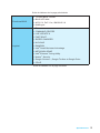
MSI B150M PRO-VDH Bedienungsanleitung
- Kategorie
- Motherboards
- Typ
- Bedienungsanleitung
Dieses Handbuch eignet sich auch für

I
Quick Start
Quick Start
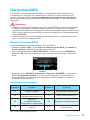
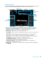
Thank you for purchasing the MSI
®
H170M PRO-VDH/ B150M PRO-
VDH motherboard. This Quick Start section provides demonstration
diagrams about how to install your computer. Some of the
installations also provide video demonstrations. Please link to the
URL to watch it with the web browser on your phone or tablet. You
may have even link to the URL by scanning the QR code.
Kurzanleitung
Danke, dass Sie das MSI
®
H170M PRO-VDH/ B150M PRO-VDH
Motherboard gewählt haben. Dieser Abschnitt der Kurzanleitung
bietet eine Demo zur Installation Ihres Computers. Manche
Installationen bieten auch die Videodemonstrationen. Klicken Sie
auf die URL, um diese Videoanleitung mit Ihrem Browser auf Ihrem
Handy oder Table anzusehen. Oder scannen Sie auch den QR Code
mit Ihrem Handy, um die URL zu öffnen.
Présentation rapide
Merci d’avoir choisi la carte mère MSI
®
H170M PRO-VDH/ B150M
PRO-VDH. Ce manuel fournit une rapide présentation avec des
illustrations explicatives qui vous aideront à assembler votre
ordinateur. Des tutoriels vidéo sont disponibles pour certaines
étapes. Cliquez sur le lien fourni pour regarder la vidéo sur votre
téléphone ou votre tablette. Vous pouvez également accéder au lien
en scannant le QR code qui lui est associé.
Быстрый старт
Благодарим вас за покупку материнской платы MSI
®
H170M
PRO-VDH/ B150M PRO-VDH. В этом разделе представлена
информация, которая поможет вам при сборке комьютера.
Для некоторых этапов сборки имеются видеоинструкции. Для
просмотра видео, необходимо открыть соответствующую ссылку
в веб-браузере на вашем телефоне или планшете. Вы также
можете выполнить переход по ссылке, путем сканирования QR-
кода.

II
Quick Start
http://youtu.be/bf5La099urI
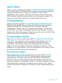
Installing a Processor/ Installation des Prozessors/ Installer
un processeur/ Установка процессора
1
2
3
6
4
5
7
8
9

III
Quick Start
1
1
2
2
3
3
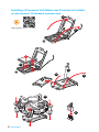
Installing DDR4 memory/ Installation des DDR4-Speichers/
Installer une mémoire DDR4/ Установка памяти DDR4
http://youtu.be/T03aDrJPyQs

IV
Quick Start
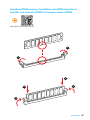
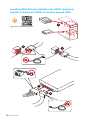
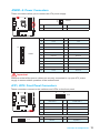
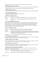
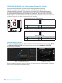
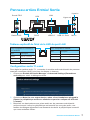
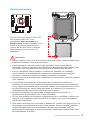
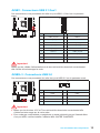
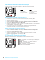
Connecting the Front Panel Header/ Anschließen der
Frontpanel-Stiftleiste/ Connecter un connecteur du panneau
avant/ Подключение разъемов передней панели
http://youtu.be/DPELIdVNZUI
1
2 10
9
JFP1
1 HDD LED + 2 Power LED +
3 HDD LED - 4 Power LED -
5 Reset Switch 6 Power Switch
7 Reset Switch 8 Power Switch
9 Reserved 10 No Pin
RESET SW
POWER SW
POWER LED+
POWER LED-
HDD LED
HDD LED
RESET SW
JFP1
HDD LED
HDD LED -
HDD LED +
POWER LED -
POWER LED +
POWER LED

V
Quick Start
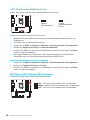
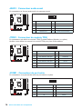
Installing the Motherboard/ Installation des Motherboards/
Installer la carte mère/ Установка материнской платы
1
2

VI
Quick Start
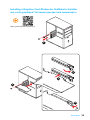
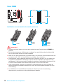
Installing SATA Drives/ Installation der SATA-Laufwerke/
Installer le disque dur SATA/ Установка дисков SATA
http://youtu.be/RZsMpqxythc
1
2
3
4
5

VII
Quick Start
1
4
5
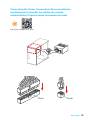
Installing a Graphics Card/ Einbau der Grafikkarte/ Installer
une carte graphique/ Установка дискретной видеокарты
http://youtu.be/mG0GZpr9w_A
2
3

VIII
Quick Start
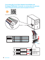
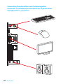
Connecting Peripheral Devices/ Peripheriegeräte/
Connecter un périphérique anschliessen/ Подключение
периферийных устройств

IX
Quick Start
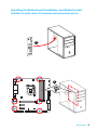
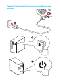
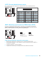
Connecting the Power Connectors/ Stromanschlüsse
anschliessen/ Connecter les câbles du module
d’alimentation/ Подключение разъемов питания
http://youtu.be/gkDYyR_83I4
JPWR1
JPWR2

X
Quick Start
Power On/ Einschalten/ Mettre sous-tension/ Включение
питания
1
4
2
3

1
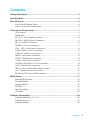
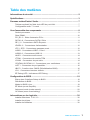
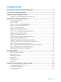
Contents
Contents
Safety Information ...................................................................................................2
Specifications ..........................................................................................................3
Rear I/O Panel ..........................................................................................................6
LAN Port LED Status Table ................................................................................. 6
Audio 7.1-channel Configuration ......................................................................... 6
Overview of Components ......................................................................................7
CPU Socket ......................................................................................................... 8
DIMM Slots .......................................................................................................... 9
PCI_E1~3: PCIe Expansion Slots...................................................................... 10
SATA1~6: SATA 6Gb/s Connectors .................................................................. 10
SE1_21: SATAe Connector ............................................................................... 10
JPWR1~2: Power Connectors ........................................................................... 11
JFP1, JFP2: Front Panel Connectors ................................................................ 11
JUSB1: USB 3.1 Gen1 Connector ..................................................................... 12
JUSB2~3: USB 2.0 Connectors......................................................................... 12
JAUD1: Front Audio Connector ......................................................................... 13
JTPM1: TPM Module Connector ....................................................................... 13
JCOM1: Serial Port Connector .......................................................................... 13
CPUFAN1,SYSFAN1~2: Fan Connectors ......................................................... 14
JLPT1: Parallel Port Connector ......................................................................... 15
JBAT1: Clear CMOS (Reset BIOS) Jumper ...................................................... 15
JCI1: Chassis Intrusion Connector .................................................................... 16
EZ Debug LED: Debug LED indicators ............................................................. 16
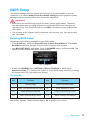
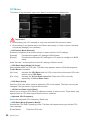
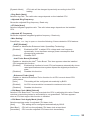
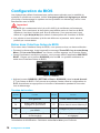
BIOS Setup .............................................................................................................17
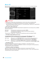
Entering BIOS Setup ......................................................................................... 17
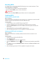
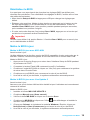
Resetting BIOS .................................................................................................. 18
Updating BIOS ................................................................................................... 18
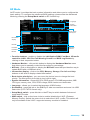
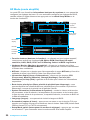
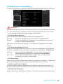
EZ Mode ............................................................................................................ 19
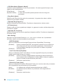
Advanced Mode ................................................................................................ 21
OC Menu ........................................................................................................... 22
Software Description ............................................................................................28
Installing Windows
®
7/ 8.1/ 10 ........................................................................... 28
Installing Drivers ................................................................................................ 28
Installing Utilities ................................................................................................ 28

2
Safety Information
Safety Information
● The components included in this package are prone to damage from electrostatic
discharge (ESD). Please adhere to the following instructions to ensure successful
computer assembly.
● Ensure that all components are securely connected. Loose connections may cause
the computer to not recognize a component or fail to start.
● Hold the motherboard by the edges to avoid touching sensitive components.
● It is recommended to wear an electrostatic discharge (ESD) wrist strap when
handling the motherboard to prevent electrostatic damage. If an ESD wrist strap is
not available, discharge yourself of static electricity by touching another metal object
before handling the motherboard.
● Store the motherboard in an electrostatic shielding container or on an anti-static pad
whenever the motherboard is not installed.
● Before turning on the computer, ensure that there are no loose screws or metal
components on the motherboard or anywhere within the computer case.
● Do not boot the computer before installation is completed. This could cause
permanent damage to the components as well as injury to the user.
● If you need help during any installation step, please consult a certified computer
technician.
● Always turn off the power supply and unplug the power cord from the power outlet
before installing or removing any computer component.
● Keep this user guide for future reference.
● Keep this motherboard away from humidity.
● Make sure that your electrical outlet provides the same voltage as is indicated on
the PSU, before connecting the PSU to the electrical outlet.
● Place the power cord such a way that people can not step on it. Do not place
anything over the power cord.
● All cautions and warnings on the motherboard should be noted.
● If any of the following situations arises, get the motherboard checked by service
personnel:
▶ Liquid has penetrated into the computer.
▶ The motherboard has been exposed to moisture.
▶ The motherboard does not work well or you can not get it work according to user
guide.
▶ The motherboard has been dropped and damaged.
▶ The motherboard has obvious sign of breakage.
● Do not leave this motherboard in an environment above 60°C (140°F), it may
damage the motherboard.

3
Specications
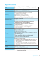
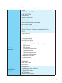
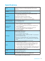
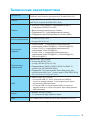
Specifications
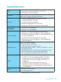
CPU
Supports 6th Gen Intel
®
Core
™
i3/i5/i7 processors, and Intel
®
Pentium
®
and Celeron
®
processors for Socket LGA1151
Chipset
Intel
®
H170 Chipset (H170M PRO-VDH)
Intel
®
B150 Chipset (B150M PRO-VDH)
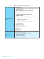
Memory
● 4x DDR4 memory slots, support up to 64GB
▶ Supports DDR4 2133 MHz
● Dual channel memory architecture
● Supports ECC, un-buffered memory
● Supports Intel
®
Extreme Memory Profile (XMP)
Expansion Slots
● 1x PCIe 3.0 x16 slot
● 2x PCIe 3.0 x1 slots
Onboard Graphics
● 1x HDMI
™
port, support a maximum resolution of
4096x2160@24Hz, 2560x1600@60Hz
● 1x DVI-D port, support a maximum resolution of
1920x1200@60Hz
● 1x VGA port, supports a maximum resolution
of 2048x1536@50Hz, 2048x1280@60Hz,
1920x1200@60Hz
Storage
Intel
®
H170/ B150 Chipset
● 6x SATA 6Gb/s ports
● 1x SATAe port (PCIe 3.0 x2)*
● Supports RAID 0, RAID 1, RAID 5 and RAID 10 (only for
H170M PRO-VDH)
● Supports Intel
®
Smart Response Technology for Intel
Core
™
processors. (only for H170M PRO-VDH)
* SATAe port is backward compatible with SATA.
USB
● Intel
®
H170/ B150 Chipset
▶ 6x USB 3.1 Gen1 (SuperSpeed USB) ports (4 ports on
the back panel, 2 ports available through the internal
USB connector)
▶ 6x USB 2.0 (High-speed USB) ports (2 ports on the
back panel, 4 ports available through the internal USB
connectors)
Audio
● Realtek
®
ALC887 Codec
● 7.1-Channel High Definition Audio
LAN 1x Realtek RTL8111H Gigabit LAN controller
Continued on next page

4
Specications
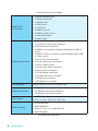
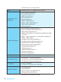
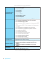
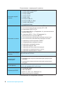
Continued from previous page
Back Panel
Connectors
● 1x PS/2 keyboard port
● 1x PS/2 mouse port
● 1x HDMI
™
port
● 1x DVI-D port
● 1x VGA port
● 2x USB 2.0 ports
● 4x USB 3.1 Gen1 ports
● 1x LAN (RJ45) port
● 3x audio jacks
Internal Connectors
● 1x 24-pin ATX main power connector
● 1x 4-pin ATX 12V power connector
● 6x SATA 6Gb/s connectors
● 2x USB 2.0 connectors (supports additional 4 USB 2.0
ports)
● 1x USB 3.1 Gen1 connector (supports additional 2 USB
3.1 Gen1 ports)
● 1x 4-pin CPU fan connector
● 2x 4-pin system fan connectors
● 1x Clear CMOS jumper
● 1x Front panel audio connector
● 2x Front panel connectors
● 1x TPM module connector
● 1x Chassis Intrusion connector
● 1x Serial port connector
● 1x Parallel port connector
I/O Controller NUVOTON NCT6793D Controller Chip
Hardware Monitor
● CPU/System temperature detection
● CPU/System fan speed detection
● CPU/System fan speed control
Form Factor
● m-ATX Form Factor
● 9.3 in. x 9.0 in. (23.5 cm x 22.8 cm)
BIOS Features
● 1x 128 Mb flash
● UEFI AMI BIOS
● ACPI 5.0, PnP 1.0a, SM BIOS 2.8
● Multi-language
Continued on next page

5
Specications
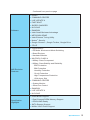
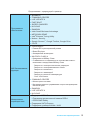
Continued from previous page
Software
● Drivers
● COMMAND CENTER
● LIVE UPDATE 6
● FAST BOOT
● SUPER CHARGER
● M-CLOUD
● RAMDISK
● Intel
®
Small Business Advantage
● NETWORK GENIE
● Intel
®
Extreme Tuning Utility
● Norton
™
Security
● Google Chrome
™
,Google Toolbar, Google Drive
● CPU-Z
MSI Exclusive
Features
● CLICK BIOS 5
▶ EZ Mode & Advanced Mode Switching
▶ Board Explorer
▶ Hardware Monitor
● MILITARY CLASS 4
▶ Military Class Component
▶ Military Class Stability and Reliability
- ESD Protection
- EMI Protection
- Humidity Protection
- Circuit Protection
- High Temperature Protection
- VGA Armor Slot
● COMMAND CENTER
▶ System Monitor
▶ Smart Fan Control
● RAMDISK
● LIVE UPDATE 6
● M-CLOUD
Specification
Highlights
● DDR4 Boost Support
▶ Dual-Channel DDR4 Memory Support
▶ DDR4 XMP Ready
● SATA Express Support
● NVMe / AHCI Driver Support

6
Rear I/O Panel
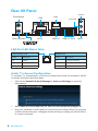
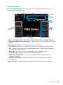
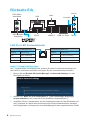
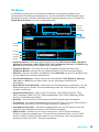
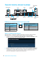
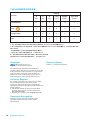
Rear I/O Panel
Link/ Activity LED
Status Description
Off No link
Yellow Linked
Blinking Data activity
Speed LED
Status Description
Off 10 Mbps connection
Green 100 Mbps connection
Orange 1 Gbps connection
LAN Port LED Status Table
PS/2 Mouse
DVI-DPS/2 Keyboard
LAN
Line-in
Line-out
Mic inUSB 3.1 Gen1
USB 2.0
VGA
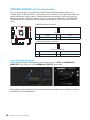
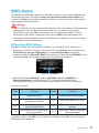
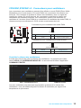
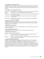
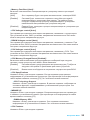
Audio 7.1-channel Configuration
To configure 7.1-channel audio, you have to connect front audio I/O module to JAUD1
connector and follow the below steps.
1. Click on the Realtek HD Audio Manager > Advanced Settings to open the
dialog below.
2. Select Mute the rear output device, when a front headphone plugged in.
3. Plug your speakers to audio jacks on rear and front I/O panel. When you plug into
a device at an audio jack, a dialogue window will pop up asking you which device
is current connected.

7
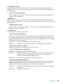
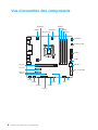
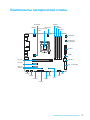
Overview of Components
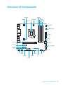
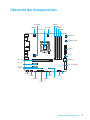
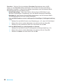
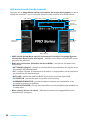
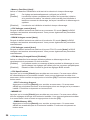
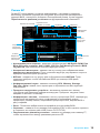
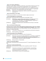
Overview of Components
CPUFAN1
JPWR2
PCI_E1
PCI_E2
PCI_E3
CPU Socket
DIMM1
SYSFAN1
DIMM2
DIMM3
DIMM4
JUSB1
JUSB2
JLPT1
JCOM1
JFP1
JFP2
SYSFAN2
EZ Debug LED
JAUD1
JBAT1
JTPM1
JPWR1
JUSB3
SATA5_6
SE1_21-SATA43
JCI1

8
Overview of Components
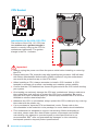
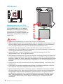
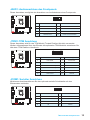
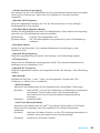
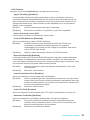
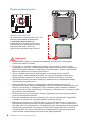
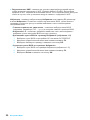
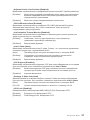
CPU Socket
Introduction to the LGA 1151 CPU
The surface of the LGA 1151 CPU has
two notches and a golden triangle to
assist in correctly lining up the CPU for
motherboard placement. The golden
triangle is the Pin 1 indicator.
Important
●
Always unplug the power cord from the power outlet before installing or removing
the CPU.
●
Please retain the CPU protective cap after installing the processor. MSI will deal
with Return Merchandise Authorization (RMA) requests if only the motherboard
comes with the protective cap on the CPU socket.
●
When installing a CPU, always remember to install a CPU heatsink. A CPU
heatsink is necessary to prevent overheating and maintain system stability.
●
Confirm that the CPU heatsink has formed a tight seal with the CPU before booting
your system.
●
Overheating can seriously damage the CPU and motherboard. Always make sure
the cooling fans work properly to protect the CPU from overheating. Be sure to
apply an even layer of thermal paste (or thermal tape) between the CPU and the
heatsink to enhance heat dissipation.
●
Whenever the CPU is not installed, always protect the CPU socket pins by covering
the socket with the plastic cap.
●
If you purchased a separate CPU and heatsink/ cooler, Please refer to the
documentation in the heatsink/ cooler package for more details about installation.
●
This motherboard is designed to support overclocking. Before attempting to
overclock, please make sure that all other system components can tolerate
overclocking. Any attempt to operate beyond product specifications is not
recommended. MSI
®
does not guarantee the damages or risks caused by
inadequate operation beyond product specifications.

9
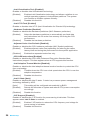
Overview of Components
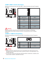
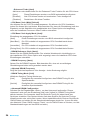
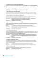
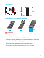
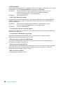
DIMM Slots
DIMM1 DIMM3
Channel A Channel B
DIMM2 DIMM4
Memory module installation recommendation
DIMM4 DIMM4
DIMM3
DIMM2 DIMM2 DIMM2
DIMM1
Important
●
Always insert memory modules in the DIMM2 slot first.
●
Due to chipset resource usage, the available capacity of memory will be a little less
than the amount of installed.
●
Based on Intel CPU specification, the Memory DIMM voltage below 1.35V is
suggested to protect the CPU.
●
Please note that the maximum capacity of addressable memory is 4GB or less
for 32-bit Windows OS due to the memory address limitation. Therefore, we
recommended that you to install 64-bit Windows OS if you want to install more than
4GB memory on the motherboard.
●
It is recommended to use a more efficient memory cooling system for full DIMMs
installation or overclocking.
●
The stability and compatibility of installed memory module depend on installed CPU
and devices when overclocking.

10
Overview of Components
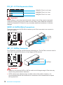
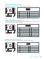
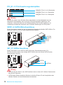
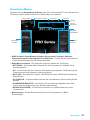
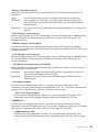
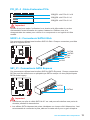
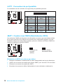
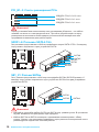
PCI_E1~3: PCIe Expansion Slots
PCI_E1: PCIe 3.0 x16 slot
PCI_E2: PCIe 3.0 x1 slot
PCI_E3: PCIe 3.0 x1 slot
Important
When adding or removing expansion cards, always turn off the power supply and
unplug the power supply power cable from the power outlet. Read the expansion
card’s documentation to check for any necessary additional hardware or software
changes.
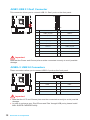
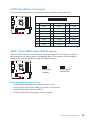
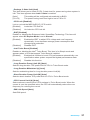
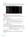
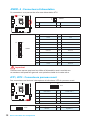
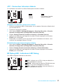
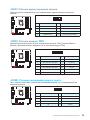
SATA1~6: SATA 6Gb/s Connectors
These connectors are SATA 6Gb/s interface ports. Each connector can connect to
one SATA device.
SATA5
SATA3
SATA2
SATA6
SATA4
SATA1
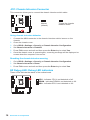
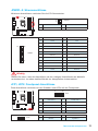
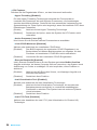
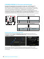
SE1_21: SATAe Connector
This connector is SATAe (SATA Express) interface port. The SATAe connector can be
used with a single SATAe device or two legacy SATA devices.
SATA1
SATA2
SATAe1
Important
●
Please do not fold the SATA or SATAe cable at a 90-degree angle. Data loss may
result during transmission otherwise.
●
SATA cables have identical plugs on either sides of the cable. However, it is
recommended that the flat connector be connected to the motherboard for space
saving purposes.
Seite wird geladen ...
Seite wird geladen ...
Seite wird geladen ...
Seite wird geladen ...
Seite wird geladen ...
Seite wird geladen ...
Seite wird geladen ...
Seite wird geladen ...
Seite wird geladen ...
Seite wird geladen ...
Seite wird geladen ...
Seite wird geladen ...
Seite wird geladen ...
Seite wird geladen ...
Seite wird geladen ...
Seite wird geladen ...
Seite wird geladen ...
Seite wird geladen ...
Seite wird geladen ...
Seite wird geladen ...
Seite wird geladen ...
Seite wird geladen ...
Seite wird geladen ...
Seite wird geladen ...
Seite wird geladen ...
Seite wird geladen ...
Seite wird geladen ...
Seite wird geladen ...
Seite wird geladen ...
Seite wird geladen ...
Seite wird geladen ...
Seite wird geladen ...
Seite wird geladen ...
Seite wird geladen ...
Seite wird geladen ...
Seite wird geladen ...
Seite wird geladen ...
Seite wird geladen ...
Seite wird geladen ...
Seite wird geladen ...
Seite wird geladen ...
Seite wird geladen ...
Seite wird geladen ...
Seite wird geladen ...
Seite wird geladen ...
Seite wird geladen ...
Seite wird geladen ...
Seite wird geladen ...
Seite wird geladen ...
Seite wird geladen ...
Seite wird geladen ...
Seite wird geladen ...
Seite wird geladen ...
Seite wird geladen ...
Seite wird geladen ...
Seite wird geladen ...
Seite wird geladen ...
Seite wird geladen ...
Seite wird geladen ...
Seite wird geladen ...
Seite wird geladen ...
Seite wird geladen ...
Seite wird geladen ...
Seite wird geladen ...
Seite wird geladen ...
Seite wird geladen ...
Seite wird geladen ...
Seite wird geladen ...
Seite wird geladen ...
Seite wird geladen ...
Seite wird geladen ...
Seite wird geladen ...
Seite wird geladen ...
Seite wird geladen ...
Seite wird geladen ...
Seite wird geladen ...
Seite wird geladen ...
Seite wird geladen ...
Seite wird geladen ...
Seite wird geladen ...
Seite wird geladen ...
Seite wird geladen ...
Seite wird geladen ...
Seite wird geladen ...
Seite wird geladen ...
Seite wird geladen ...
Seite wird geladen ...
Seite wird geladen ...
Seite wird geladen ...
Seite wird geladen ...
Seite wird geladen ...
Seite wird geladen ...
Seite wird geladen ...
Seite wird geladen ...
Seite wird geladen ...
Seite wird geladen ...
Seite wird geladen ...
Seite wird geladen ...
Seite wird geladen ...
Seite wird geladen ...
Seite wird geladen ...
Seite wird geladen ...
Seite wird geladen ...
Seite wird geladen ...
Seite wird geladen ...
Seite wird geladen ...
Seite wird geladen ...
Seite wird geladen ...
Seite wird geladen ...
Seite wird geladen ...
Seite wird geladen ...
Seite wird geladen ...
-
 1
1
-
 2
2
-
 3
3
-
 4
4
-
 5
5
-
 6
6
-
 7
7
-
 8
8
-
 9
9
-
 10
10
-
 11
11
-
 12
12
-
 13
13
-
 14
14
-
 15
15
-
 16
16
-
 17
17
-
 18
18
-
 19
19
-
 20
20
-
 21
21
-
 22
22
-
 23
23
-
 24
24
-
 25
25
-
 26
26
-
 27
27
-
 28
28
-
 29
29
-
 30
30
-
 31
31
-
 32
32
-
 33
33
-
 34
34
-
 35
35
-
 36
36
-
 37
37
-
 38
38
-
 39
39
-
 40
40
-
 41
41
-
 42
42
-
 43
43
-
 44
44
-
 45
45
-
 46
46
-
 47
47
-
 48
48
-
 49
49
-
 50
50
-
 51
51
-
 52
52
-
 53
53
-
 54
54
-
 55
55
-
 56
56
-
 57
57
-
 58
58
-
 59
59
-
 60
60
-
 61
61
-
 62
62
-
 63
63
-
 64
64
-
 65
65
-
 66
66
-
 67
67
-
 68
68
-
 69
69
-
 70
70
-
 71
71
-
 72
72
-
 73
73
-
 74
74
-
 75
75
-
 76
76
-
 77
77
-
 78
78
-
 79
79
-
 80
80
-
 81
81
-
 82
82
-
 83
83
-
 84
84
-
 85
85
-
 86
86
-
 87
87
-
 88
88
-
 89
89
-
 90
90
-
 91
91
-
 92
92
-
 93
93
-
 94
94
-
 95
95
-
 96
96
-
 97
97
-
 98
98
-
 99
99
-
 100
100
-
 101
101
-
 102
102
-
 103
103
-
 104
104
-
 105
105
-
 106
106
-
 107
107
-
 108
108
-
 109
109
-
 110
110
-
 111
111
-
 112
112
-
 113
113
-
 114
114
-
 115
115
-
 116
116
-
 117
117
-
 118
118
-
 119
119
-
 120
120
-
 121
121
-
 122
122
-
 123
123
-
 124
124
-
 125
125
-
 126
126
-
 127
127
-
 128
128
-
 129
129
-
 130
130
-
 131
131
-
 132
132


MSI B150M PRO-VDH Bedienungsanleitung
- Kategorie
- Motherboards
- Typ
- Bedienungsanleitung
- Dieses Handbuch eignet sich auch für
in anderen Sprachen
Verwandte Artikel
-
MSI MS-7979 v1.0 Bedienungsanleitung
-
MSI MS-7A46 v1.0 Bedienungsanleitung
-
-
-
-
-
-
-
-