
BINARIO TRIFASE
art. 7501 440V 16A CL1
Il binario ed i suoi componenti, compresi gli
adattatori in CI 1 non sono intercambiabili con
sistemi a binario di classe III o con accessori
che non riportino il Marchio di Qualità.
E’ responsabilità dell’utente assicurare la
compatibilità elettrica, meccanica e termica tra i
sistemi a binario e gli apparecchi ad esso
connessi.
Montaggio
Installare il binario tramite i fori già predisposti
sul profilato oppure utilizzando gli accessori art.
7606 - Kit di sospensione oppure art. 7607 - Kit
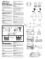
soffitto, coi limiti di carico indicati nella fig. 5.
CONNETTORI DI ALIMENTAZIONE ART.
7602 DX ART. 7602 SX 440V 16A
Collegamento:
Aprire il vano portacontatti, svitando le due viti
come indicato nella fig. 2.
Sfondare la prerottura per il passaggio del cavo,
collegare i conduttori facendo attenzione alla
dicitura N L1 L2 L3 T e successivamente
bloccarli tramite il ponticello fermacavo.
Montaggio:
Inserire il connettore nel binario facendo
attenzione al corretto orientamento (Dx o Sx) e
quindi bloccarlo con la vite A come da fig. 2.
ALIMENTAZIONE CENTRALE ART. 7603
440V 16A
Collegamento:
Aprire il vano portacontatti svitando le quattro
viti come indicato in fig. 3.
Sfondare la prerottura per il passaggio del cavo,
collegare i conduttori facendo attenzione alla
dicitura N L1 L2 L3 T e successivamente
bloccarli tramite il ponticello fermacavo.
Montaggio:
Inserire il connettore nel binario facendo
attenzione al corretto orientamento (Dx o Sx) e
quindi bloccarlo con le viti A come da fig. 3.
ADATTATORE PER BINARIO ART. 7601
250V 6A
Collegamento:
Svitare le tre viti come da fig. 4A
Inserire il cavo dell’apparecchio attraverso il foro
della bussola di rotazione e fissarlo con
l’apposito ponticello come da fig. 4D
Collegare i tre conduttori facendo attenzione alla
dicitura L N T come da fig. 4B e 4C-
Rimontare e fissare il coperchio.
L’uso è limitato al sistema binario specificato
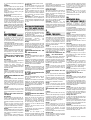
Montaggio:
Inserire l’adattatore nel binario con la leva D
orientata come da fig. 6 posizione F e quindi
bloccarlo ruotandola dalla posizione F alla
posizione G. Selezionare quindi la fase
desiderata tramite la manopola E come da fig.
6. Non applicare apparecchi di peso superiore a
50N.
Montaggio a parete
Nel caso del montaggio a parete con binario in
posizione orizzontale, non applicare
all’adattatore un momento flettente superiore ad
1Nm
Nel caso di montaggio a parete con binario in
posizione verticale, la scanalatura di guida del
profilato del binario deve essere a destra; non
applicare all’adattatore un momento flettente
superiore a 2Nm.
Attenzione! Per l’installazione di faretti aventi
un peso superiore a 50N o che superano i
momenti flettenti rispettivamente di 1Nm e 2Nm,
utilizzare l’adattatore meccanico art. 7625.
UK
THREE-PHASE TRACK
ART. 7501 440V 16A CL1
The track and its components, including
adapters in Class I, are not interchangeable
with track systems in Class III or with
accessories which do not show the Quality
Mark.
The responsibility to ensure the electric,
mechanical and termic compatibility between
track systems and connected fittings rests with
the user.
Installation
Install the track by the holes on its surface or by
using the accessories art. 7606 - suspension
kit, or art. 7607 - ceiling kit, respecting the load
limits shown in pic. 5.
LIVE-ENDS ART. 7602 DX ART. 7602 SX
440V 16A
Connection:
Open the case with contacts by unscrewing the
two screws as in pic. 2.
Break the bottom of the suitable hole to let the
cable pass through. Connect the wires paying
attention to the caption N L1 L2 L3 T and then
fix them by the strain relief.
Installation:
Insert the live-end into the track, paying
attention to the right orientation (Dx or Sx) and
then fix it by the screw A, as in pic. 2.
CENTRAL CONNECTOR ART. 7603
440V 16A
Connection:
Open the case with contacts by unscrewing the
four screws as in pic. 3.
Break the bottom of the suitable hole to let the
cable pass through. Connect the wires paying
attention to the caption N L1 L2 L3 T and then
fix them by the strain relief.
Installation:
Insert the connector into the track, paying
attention to the right orientation (Dx or Sx) and
then fix it by the screws A as in pic. 3.
TRACK ADAPTER ART. 7601 250V 6A
Connection:
Unscrew the three screws as in pic. 4A.
Insert the cable of the fitting into the rotation
washer and fix it by the suitable device, as in
pic. 4D. Connect the three wires paying
attention to the caption L N T , as in pic. 4B and
FIG. 1
FIG. 2
FIG 2
FIG 3
FIG 4A
FIG 4B
FIG 4C
FIG 6
FIG 4D
F
E
GD
AA
AA
DESTRO
RIGHT
SINISTRO
LEFT
}
16A
16A
N
L1
L2
L3
16A
AUTOMAT
N
L
16A N
L1
L2
L3
N
L1
L2
L3
max
16A
16A
16A
200 200 200 200
2 kg 2 kg 2 kg 2 kg 2 kg
800
200 200 200 200
10 kg 10 kg 10 kg 10 kg 10 kg
400 400
16A
N
L1
N
L
16A
Automat
SCHEMA ELETTRICO
CARICO MASSIMO
FIG. 5
DX
SX
IVELA
max 0,25 N/m

90-06023-31 —LT 117 – 05/05/2001
4C. - The use is limited to the specified track
system.
Installation:
Insert the adapter into the track with the
lever D oriented as in pic. 6, position F, and
then fix it turning it from the position F to the
position G.
Select the phase you wish by using the
handgrip E, as in pic. 6.
Do not install fittings with load over 50 N .
Wall mounting
In case of wall mounting with track in
horizontal position, do not apply a moment
of flexure over 1 Nm to the adapter.
In case of wall mounting with track in vertical
position, the guide groove of the track
surface must be on the right. Do not apply a
moment of flexure over 2 Nm to the adapter.
Warning! To install fittings weighing over 50
N, or exceeding the moments of flexure of
respectively 1 Nm and 2 Nm use the
mechanical adapter art. 7625.
F
RAIL TRIPHASE’
Art. 7501 440V 16A CL1
Le rail et ses composants, inclus les
adaptateurs en CI. I ne sont pas
interchangeables avec des systèmes rail en
CI. III ou avec des accessoires qui n’ont pas
le Marquage de Qualité.
C’est résponsabilité de l’utilisateur assûrer la
compatibilité électrique, mécanique et
thermique entre les systèmes rail et les
appareils branchés.
Montage
Installer le rail par les trous présents sur le
profilé ou utilisant les accessoires art. 7606 -
kit suspension, ou art. 7607 - kit plafond,
avec les limites de charge indiquées dans la
fig. 5.
CONNECTEURS D’ALIMENTATION
ART. 7602 DX ART. 7602 SX 440V
16A
Branchement:
Ouvrir le boîtier des contacts, dévissant les
deux vis comme dans la fig. 2.
Percer la pre-ouverture prévue pour le
passage du câble; brancher les
conducteurs, faisant attention à la légende N
L1 L2 L3 T et successivement les fixer par le
dispositif serre-câble.
Montage:
Insérer le connecteur dans le rail faisant
attention à l’orientation correcte (Dx ou Sx);
après le fixer par la vis A comme dans la fig.
2.
ALIMENTATION MÉDIANE ART. 7603
440 V 16A
Branchement:
Ouvrir le bôitier des contacts, dévissant les
quatre vis comme dans la fig. 3. Percer la
pre-ouverture prévue pour le passage du
câble, brancher les conducteurs, faisant
attention à la légende N L1 L2 L3 T et
successivement les fixer par le dispositif
serre-câble.
Montage:
Insérer le connecteur dans le rail, faisant
attention à l’orientation correcte (Dx ou Sx)
et après le fixer par les vis A comme dans la
fig. 3.
ADAPTATEUR POUR RAIL ART.
7601 250V 6A
Branchement:
Dévisser les trois vis comme dans la fig. 4A.
Insérer le câble de l’appareil dans le trou de
la douille de rotation et le fixer par le
dispositif correspondant, comme dans la fig.
4D.
Brancher les trois conducteurs faisant
attention à la légende L N T comme dans la
fig. 4B et 4C.Remonter et fixer le couvercle.
L’emploi est limité au systéme rail spécìfié
Montage:
Insérer l’adaptateur dans le rail avec le levier
D orienté comme dans la fig. 6, position F, et
après le fixer par la rotation de la position F
à la position G.
Après sélectionner la phase désirée par la
poignée E, comme dans la fig. 6. N’installez
pas d’appareils de poids supérieur à 50 N.
Montage à mur
En case de montage à mur avec le rail en
position horizontale, n’appliquez pas à
l’adaptateur un moment de flexion supèrieur
à 1 Nm.
En cas de montage à mur avec le rail en
position verticale, la rainure de guide du
profilé du rail doit être à droite; n’appliquez
pas à l’adaptateur un moment de flexion
supérieur à 2 Nm.
ATTENTION! Pour l’installation de spots de
poids supérieur à 50 N, ou dépassant les
moments de flexion respectivement de 1 Nm
et 2 Nm, employer l’adaptateur mécanique
art. 7625.
D
DREIPHASENSTROMSCHIENE
Art. 7501 440V 16A CL1
Die Stromschiene und ihre Komponenten,
inbegriffen die Adapter in Kl, sind nicht
auswechselbar mit Stromschienesysteme in
KI. III oder mit Zubehören, die kein
Qualitätzeichen zeigen.
Der Benutzer ist dafür verantwortlich, die
elektrische, mechanische und thermische
Kompatibilität zwischen den
Stromschienesystemen und den
verbundenen Strahlern zu sichern.
Montage
Installieren Sie die Stromschiene durch die
auf dem Profil vorgebohrten Löcher, oder
benutzen Sie die Zubehöre Art. 7606 -
Stahlseil-Abhänger oder Art. 7606 - Kit für
Decke, indem Sie die Ladengrenzen wie aus
Bild 5 beachten.
EINSPEISUNGSSTÜCKE ART. 7602
DX
ART. 7602 SX 440V 16A
Verbindung:
Öffnen Sie das Kontaktsgehäuse, indem Sie
die zwei Schrauben wie im Bild 2
abschrauben.
Schlagen Sie den Boden der vorbereiteten
Öffnung aus, um das Kabel durchzuziehen;
verbinden Sie die Leitungen, indem Sie auf
die Aufschrift N L1 L2 L3 T achtgeben. Dann
befestigen Sie sie durch die Klemme.
Montage:
Stecken Sie das Einspeisungsstück in die
Stromschiene, indem Sie auf die richtige
Orientierung (Dx oder Sx) achtgeben, und
dann befestigen Sie es mit der Schraube A
wie aus Bild 2.
MITTLERES EINSPEISUNGSSTÜCK
ART. 7603 440V 16A
Verbindung:
Öffnen Sie das Kontaktsgehäuse, indem sie
die vier Schrauben wie aus Bild 3
abschrauben.
Schlagen Sie den Boden der vorbereiteten
Öffnung aus, um das Kabel durchzuziehen;
verbinden Sie die Leitungen, indem Sie auf
die Aufschrift N L1 L2 L3 T achtgeben, und
dann befestigen Sie sie mit der Klemme.
Montage:
Stecken Sie das Einspeisungsstück in die
Stromschiene, indem Sie auf die richtige
Orientierung (Dx oder Sx) achtgeben, und
dann befestigen Sie es mit den Schrauben A
wie aus Bild 3.
STECKADAPTER ART. 7601 250V 6A
Verbindung:
Schrauben Sie die drei Schrauben wie aus
Bild 4A ab. Stecken Sie das Kabel des
Strahlers ins Loch der Büchse und
befestigen Sie es mit der besonderen
Vorrichtung wie aus Bild 4D. Verbinden Sie
die drei Leitungen, indem Sie auf die
Aufschrift L N T wie aus Bild 4B und 4C
achtgeben.
Legen Sie die Decke wieder auf und
befestigen Sie sie.
Die Benutzung wird zum angegebenen
Schienensystem eingeschränkt.
Montage:
Stecken Sie den Adapter in die
Stromschiene mit dem Hebel D wie aus Bild
6, Lage F, gerichtet, dann befestigen Sie
ihn, indem Sie den Hebel von der Lage F zur
Lage G drehen.
Dann wählen Sie die gewünschte Phase
durch den Griff E wie aus Bild 6 aus.
Installieren Sie keine Strahler mit einem
Gewicht größer als 50 N.
Montage an der Wand
Wenn Sie die Stromschiene horizontal an
die Wand installieren, legen Sie dem
Adapter ein Moment von Biegung nicht
größer als 1 Nm an.
Wenn Sie die Stromschiene senkrecht an
die Wand installieren, muß die Führungsnut
des Profils der Stromschiene rechts sein:
legen Sie dem Adapter ein Moment von
Biegung nicht größer als 2 Nm an.
ACHTUNG! Benutzen sie den
mechanischen Adapter Art. 7625, um
Strahler mit einem Gewicht größer als 50 N
zu installieren, oder wenn sie die Momente
von Biegung beziehungsweise von 1 Nm
und 2 Nm übersteigen.
E
7501
CARRIL TRIFASICO
El carril y sus componentes, incluidos los
adaptadores en CI 1
no son intercambiables
con sistemas de carril de Clase III o con
accesorios que no reportan la marca de
calidad. Es responsabilidad del usuario
asegurar la compatibilidad electrica,
mecanica y termica entre los sistemas de
carril y los aparatos utilizados.
Montaje
Instalar el carril por los aujeros ya
predispuestos sobre la guìa o bien utilizar
los accesorios, art. 7606, Kit de suspension
o art. 7607, Kit techo con los limites de
carga indicados en la figura 5.
CONECTORES DE ALIMENTACION, ART.
7602 DX ART. 7602 SX 440V 16A
Conexiòn
Abrir la caja portacontactos, destornillando
los dos tornillos como indicado en la fig. 2.
Desfondar el plastico para pasar el cable,
juntar los conductores poniendo atenciòn a
los simbolos N L1 L2 L3 T, y sucesivamente
blocarlos con el dispositivo de anclaje.
Montaje
Insertar el conector en el carril, poniendo
atenciòn a la correcta orientacion (Dx o Sx)
y luego blocarlo por el tornillo A, como de
fig. 2.
ALIMENTACION CENTRAL ART. 7603
440V 16A
Conexion
Abrir la caja portecontactos destornillando
los cuatros tornillos, como indicado en la fig.
3.
Desfondar el plastico para pasar el cable,
juntar los conductores poniendo atencion a
los simbolos N L1 L2 L3 T, y sucesivamente
blocarlos con el dispositivo de conexion.
Montaje:
Insertar el conector en el carril, poniendo
atenciòn a la correcta orientaciòn (Dx o Sx)
y luego blocarlo por los tornillos A, como de
fig. 3.
ADAPTADOR POR CARRIL art. 7601 250V
6A
Conexion:
Destornillar los tres tornillos como en la fig.
4A.
Insertar el cable del aparato por el aujero de
la aguja de rotaciòn y fijarlo por su
dispositivo como en la fig. 4D. Juntar los tres
conductores poniendo atenciòn a los
simbolos L N T como en las fig. 4B y 4C.
Remontar y fijar la tapa.
Montaje:
Insertar el adaptador en el carril con la
palanca D orientada como en la fig. 6,
posiciòn F y luego blocarlo, ruedandola de la
posiciòn-F a la posiciòn G. Luego
seleccionar la fase deseada por la monopla
E como en la fig. 6.
No aplicar aparatos de peso superior a 50N.
Montaje a pared
En caso de montaje a pared con carril en
posiciòn horizontal, no aplicar al adaptador
un momento superior a 1 Nm.
En caso de montaje a pared con carril en
posiciòn vertical, la acanaladura de guia de
la extrusion del carril debe estar a la
derecha; no aplicar al adaptador un
momento doblante superior a 2Nm.
ATENCION!
Por la instalaciòn de focos con un peso
superior a 50N o con momentos
respectivamente de 1 Nm y 2 Nm, utilizar el
adaptador mecanico art. 7625.
NL
DRIEFAZIGE RAIL
Art. 7501 440V 16A CL1
De rail en toebehoren, de adapters
inbegrepen, in Klasse I zijn niet
uitwisselbaar met railsystemen van Klasse
III of door accessoires die niet voorzien zijn
van het KwaliteitsMerk.
De gebruiker moet zich verzekeren van de
electrische, mechanische en thermische
compatibiliteit tussen de railsystemen en de
aangesloten toestellen.
Montage
Installeer de rail door middel van de gaten in
het profiel of gebruik de accessoires art.
7606 -kit ophanging, of art. 7607 -kit
plafondbevestiging. Hou rekening met de
maximum belasting (fig.5).
VOEDING ART. 7602 DX ART. 7602 SX
440V 16A
Aansluiting
Open de contactdoos door de twee vijzen
los te schroeven (fig.2). Doorboor de
voorgemaakte opening voor de kabel; sluit
de voedingsdraden aan. Let hierbij op de
legende N Ll L2 L3 T. Maak daarna de
voedingsdraden vast in de trekontlasting.
Montage
Bevestig de voeding in de rail. Let op de
juiste richting (Dx of Sx). Maak vast met de
vijs (A) zoals op fig.2.
CENTRALE VOEDING ART. 7603 440V
16A
Aansluiting
Open de contactdoos door de vier vijzen los
te schroeven (fig.3). Doorboor de
voorgemaakte opening voor de kabel; sluit
de voedingsdraden aan. Let hierbij op de
legende N L1 L2 L3 T. Maak daarna de
voedingsdraden vast in de trekontlasting.
Montage
Bevestig de voeding in de rail. Let op de
juiste richting (Dx of Sx). Maak vast met de
vijzen (A) zoals op fig.2 & 3.
ADAPTER VOOR RAIL ART. 7601 2
50V 6A
Aansluiting
Schroef de drie vijzen los (fig.4A). Bevestig
de kabel van het toestel in de opening van
de trekontlasting
en maak vast in de betreffende punten,
zoals op fig.4D. Sluit de drie draden aan. Let
op de legende LNT (fig.4B en 4C). Maak het
deksel terug vast. Het gebruik is beperkt tot
het specifieke railsysteem.
Montage
Duw de adapter in de rail. Zet hiervoor de
hendel (D) in de positie F (zie fig.6). Om te
bevestigen, beweeg de hendel van positie F
naar positie G. Kies met de handgreep (E)
de gewenste stand (zie fig.6). Installeer
geen toestellen zwaarder dan 50N.
Montage aan de muur
In geval van horizontale montage aan de
muur mag U op de adapter niet meer dan
lNm buigmoment toepassen.
In geval van verticale montage aan de muur
moet de gleuf in het profiel zich rechts
bevinden en mag U op de adapter niet meer
dan 2Nm buigmoment toepassen.
Belangrijk !
Indien de spots zwaarder zijn dan 50N of
wanneer het buigmoment groter is dan
respectievelijk lNm en 2Nm, gebruik dan de
mechanische adapter art. 7625.
-
 1
1
-
 2
2


Deko-light 444200 Bedienungsanleitung
- Typ
- Bedienungsanleitung
- Dieses Handbuch eignet sich auch für
in anderen Sprachen
- English: Deko-light 444200 Owner's manual
- français: Deko-light 444200 Le manuel du propriétaire
- español: Deko-light 444200 El manual del propietario
- italiano: Deko-light 444200 Manuale del proprietario
- Nederlands: Deko-light 444200 de handleiding


