
Montageanleitung
Assembly Instructions
GSS
Grundig Systems GmbH
Beuthener Straße 43
D-90471 Nürnberg
Telefon: +49 (0) 911 / 703 8877
Fax: +49 (0) 911 / 703 9210
Email: [email protected]
Internet: http://www.gss.de
Deutsch
English
STA 1000 / STA 855 / STA 755
Parabolantennen
Parabolic antennas

- 2 -
1 Safety and hazards
– Earth the SAT receiver system
in accordance with the relevant
guidelines (DIN EN 50083 / EN
60728, VDE 855).
– Never handle the antenna system dur-
ing a thunderstorm.
– Keep the minimum distance to the
overhead line when assembling the
parabolic antenna.
– Due to atmospheric or static dis-
charge, never assemble the parabolic
antenna on inflammable roofing, such
as thatched or straw roofs etc.
– An electrician must carry out the
assembly of the antenna.
– Use a safety harness when assem-
bling the parabolic antenna on the
roof or other places where there is
a risk of falling.
– Only use ladders or climbing assist-
ance which are in proper working or-
der.
– Check the surface is able to bear
weight before assembly.
– Only install the parabolic antenna on
sufficiently stable walls or floors.
– Protect passers-by from any falling ob-
jects.
– Observe the relevant standards,
regulations and guidelines on the in-
stallation and operation of antenna
systems.
– You can obtain additional informa-
tion from the “Planning handbook”
brochure which can be found on the
website “http://www.gss.de”.
1 Sicherheit und Gefährdungen
– Erden Sie die SAT-Empfangs-
anlage gemäß den relevanten
Vorschriften (DIN EN 50083 /
EN 60728, VDE 855).
– Arbeiten Sie nie während eines Gewit-
ters an Antennenanlagen.
– Halten Sie bei der Montage der Pa-
rabolantenne die Mindestabstände zu
Freileitungen ein.
– Montieren Sie wegen atmosphärischer
oder statischer Entladungen die Pa-
rabolantenne nie auf leicht entzünd-
lichen Dacheindeckungen (z.B. Reet,
Stroh etc.).
–
Die Montage der Antenne ist von
Elektrofachkräften durchzuführen.
– Verwenden Sie während der Mon-
tage der Parabolantenne auf Dächern
oder absturzgefährdeten Stellen einen
Sicherheitsgurt.
– Verwenden Sie nur intakte Steighilfen
oder Leitern.
– Prüfen Sie vor der Montage die Trag-
fähigkeit der zu betretenden Flächen.
– Montieren Sie die Parabolantenne nur
an ausreichend stabilen Wand- oder
Bodenkonstruktionen.
– Schützen Sie Passanten vor herabfal-
lenden Gegenständen.
– Beachten Sie die relevanten Normen,
Vorschriften und Richtlinien zur Instal-
lation und zum Betrieb von Antennen-
anlagen.
– Weitere Informationen entnehmen
Sie bitte der Broschüre “Planungs-
handbuch”, die Sie auf der Webseite
“http://www.gss.de” finden.

- 3 -
2 General
2.1 Available accessories
See website “ht tp://www.gss.de”.
2.2 Symbols used
Important note
Danger by electrical shock
• Performing works
3 Installation
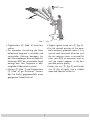
3.1
Completing
STA 1000
8 69
@!0#734 2
1
5
7
Abb. 1 / Fig.1
2 Allgemeines
2.1 Lieferbares Zubehör
Siehe Webseite “http://ww w.gss.de”.
2.2 Verwendete Symbole
Wichtiger Hinweis
Gefährdung durch elektrischen
Schlag
• Durchführen von Arbeiten
3 Montage
3.1 STA 1000 komplettieren

- 4 -
- 4 -
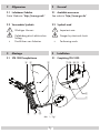
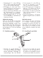
• Attach the bracket 1 with the screws
3 (6 in total) and the accompanying
nuts 4 on the reflector of the para-
bolic antenna 2.
• Fit the connector 5 in the LNB sup-
port arm
6 and fasten it with the
screws 7 from below and above.
• Insert the LNB support arm 6 through
the opening in the reflector into the
fastening position 8 and attach with
screw 9.
• Join the parts 0 and ! of the LNB
holder and the connector 5 so they
enclose the LNB.
•
Screw the joined parts 5, 0 and
! together using the screw @ and
nut #.
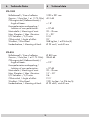
3.2 Completing STA 755 / STA 855
Abb. 2 / Fig.2
• Haltebügel 1 mit den Schrauben
3
(Anzahl 6) und den zugehörigen Mut-
tern 4 am Reflektor der Parabolan-
tenne 2 befestigten.
• Verbindungsteil 5 in den LNB-Trag-
arm
6 stecken und mit den Schrauben
7 von unten und oben befestigen.
• LNB-Tragarm 6 durch den Durch-
bruch im Reflektor in die Befestigungs-
hülse 8 stecken und mit Schraube 9
befestigen.
• Teile 0 und ! des LNB-Halters und
das Verbindungsteil 5 so zusammen-
fügen, dass sie das LNB umschließen.
• Zusammengefügte Teile 5, 0 und
! mit Schraube @ und Mutter #
zusammenschrauben.
3.2 STA 755 / STA 855 komplettieren
76583
24
1
3

- 5 -
- 5 -
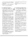
• Verbindungsteil 1 in den LNB-Trag-
arm 2 stecken und mit den Schrau ben
3 von unten und oben befestigen.
• LNB-Tragarm
2 durch den Durch-
bruch im Reflektor bis zum Einrasten in
die Befestigungshülse
4 stecken.
• Teile 5 und 6 des LNB-Halters und
das Verbindungsteil 1 so zusammen-
fügen, dass sie das LNB umschließen.
• Zusammengefügte Teile 1, 5 und
6 mit Schraube 7 und Mutter 8
zusammenschrauben.
Multifeed-Erweiterung
Sollen mit der STA 855 z.B. die Satel-
liten Astra und Eutelsat II F1/Hotbird 1
gleichzeitig empfangen werden, kann
der LNB-Halter durch den Nachrüstsatz
STM 2 ersetzt werden. Dieser ermöglicht
die Montage von 2 LNBs zum Empfang
beider Satelliten.
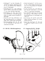
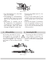
3.3 Masthalter montieren
• Masthalter A gemäß Abbildung 3
so mit dem am Reflektor der Parabol-
antenne befestigten Haltebügel B
zusammenfügen, dass der Masthal-
Abb. 3 / Fig. 3
• Fit the connector 1 in the LNB sup-
port arm 2 and fasten it with the
screws
3 from below and above.
• Insert LNB support arm
2 through the
opening in the reflector and into the
fastening position until it catches
4.
• Join the parts 5 and 6 of the LNB
holder and the connector 1 so they
enclose the LNB.
• Screw the joined parts 1, 5 and 6
together using the screw 7 and nut
8 .
Multi-feed extension
If, for instance, the Astra and Eutelsat
II F1 / Hotbird 1 satellites are received
simultaneously using the STA 855, the
LNB holder can be replaced with the
STM 2 retrofit set. This enables two LNBs
to be installed for reception from both
satellites.
3.3 Assembling the mast holder
• Connect the mast holder A accord-
ing to fig. 3, with the bracket B on
the reflector of the parabolic antenna
so that the mast holder
A can be fas-
!

- 6 -
tened through the bracket B with the
screws C .
• Fasten the screws
C with the nuts D
loosely.
3.4 Assembling the parabolic antenna
– To ensure good reception, make
sure there are no obstacles po-
sitioned between the parabolic
antenna and the satellite, such as
trees, houses etc.
– Assemble the antenna mast or the wall
bracket in an upright position other-
wise problems could arise when align-
ing the parabolic antenna.
– For mounting the parabolic antenna
on the roof, use a suitable steel
pole or
mast with a thickness of at least 2 mm
and an appropriate diameter to the
parabolic antenna mast holder.
– Make sure when mounting the mast
that at least
1
/
6
of the whole mast
length is clamped.
– When attaching the antenna mast on
a wooden beam, use the required
clamps and a mast stand, and screws
with a diameter of at least 8 mm.
Heavy-duty dowels must be used for
attaching to brickwork.
– Earth the antenna mast according to
the guidelines.
– We recommend using the wall brack-
ets for the parabolic antenna when
mounting on the wall (see website
“http://www.gss.de”).
ter
A mit den durch den Haltebügel
B gesteckten Schrauben C befestigt
werden kann.
• Schrauben C mit den zugehörigen
Muttern D nur leicht befestigen.
3.4 Parabolantenne montieren
– Um einen guten Empfang sicher-
zustellen, beachten Sie, dass sich
keine Hindernisse zwischen der
Parabolantenne und dem jeweiligen
Satelliten befinden (z.B. Bäume, Häu-
ser etc.).
– Montieren Sie den Antennenmast oder
die Wandhalterung senkrecht, da es
sonst Prob
leme beim Ausrichten der
Parabolantenne geben kann.
– Verwenden Sie für die Dachmontage
der Parabolantenne geeignete Stahl-
rohre oder Masten mit einer Wandstär-
ke von mindestens 2 mm und einem
dem Masthalter der Parabolantenne
entsprechenden Durchmesser.
– Beachten Sie bei der Mastmontage,
dass mindestens
1
/
6
der Gesamt länge
des Masts eingespannt sein muss.
– Verwenden Sie für die Befestigung
des Antennenmasts an Holzbalken
die erforderlichen Schellen bzw. ei-
nen Mastfuß und Schrauben mit einem
Mindestdurchmesser von 8 mm. Für
die Befestigung an Mauerwerk müssen
Schwerlastdübel verwendet werden.
– Antennenmast gemäß den relevanten
Vorschriften erden.
– Für die Wandmontage empfehlen wir
die der Parabolantenne entsprechen-
de Wandhalterung (s. Webseite
”http://www.gss.de”).

- 7 -
- 7 -
• Zwei Masthaltebügel E in den Mast-
halter A einhängen.
• Masthaltebügel E und Parabolanten-
ne gemäß Abb. 4 am Antennenmast
oder an der Wandhalterung positio-
nieren.
• Mastschellen F schließen und mit
den Flügelmuttern G Parabolanten-
ne am Mast bzw. am Wandhalter nur
leicht befestigen, sodass die weitere
Montage durchgeführt werden kann.
4 LNB anschließen
Der Anschluss des LNB muss wasser-
dicht ausgeführt sein. Verwenden Sie
zum Abdichten gegebenenfalls eine
Gummi-Dichtungstülle, ein Dichtungs-
band oder ein LNB mit Wetterschutzge-
häuse.
Abb. 4 / Fig. 4
7
12
7
12
Abb. 5 / Fig. 5
• Hang two mast holder hooks E in the
mast holder A .
• Position the mast holder hooks E and
parabolic antenna according to fig. 4
on the antenna mast or on the wall
bracket.
• Close the mast clamps F and loosely
fasten the parabolic antenna on the
mast or wall bracket using the thumb
nuts G so the rest of the assembly can
still be carried out.
4 Connecting the LNB
Connecting the LNB must be done
in dry conditions. If necessary, use
a rubber sealing grommet, a sealing
band or a LNB with a weather-proof
housing.
"
#
$

- 8 -
- 8 -
• Guide the required number of antenna
cables through the LNB support arm to
the LNB.
• If necessary, put rubber sealing grom-
mets on the antenna cable.
• Install F connectors on the antenna ca-
bles according to figure 5 and fasten
tightly to the LNB.
• Seal the LNB connections.
5 Aligning the parabolic antenna
• Connect the LNB output to an antenna
tester or a satellite receiver.
• Tune the connected device to a trans-
ponder which can be received.
• Set the elevation angle (tilting) of the
parabolic antenna using the scale on
the mast holder A to approx. 30°
(fig. 3).
• Slightly tighten nuts D (fig. 3).
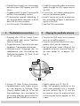
• Align the parabolic antenna to the
south and gradually turn it towards
the east (Azimut) (fig. 6, 7) until the
test receiver shows the maximum level
or the required station appears on the
screen.
• Erforderliche Anzahl von Antennenka-
beln durch den LNB-Tragarm zum LNB
führen.
• Gegebenenfalls Gummi-Dichtungstülle
auf das Antennenkabel stecken.
• F-Connectoren gemäß Abbildung 5
am Antennenkabel montieren und mit
dem LNB fest verschrauben.
• Anschlüsse des LNB abdichten.
5 Parabolantenne ausrichten
• Ausgang des LNB mit einem Anten-
nenmessgerät oder einem Satelliten-
Receiver verbinden.
• Angeschlossenes Gerät auf einen emp-
fangbaren Transponder abstimmen.
• Elevationswinkel (Neigung) der Pa-
rabolantenne unter Verwendung der
Skala am Masthalter A (Abb. 3) auf
ca. 30° einstellen.
• Muttern D (Abb. 3) leicht festziehen.
•
Parabolantenne nach Süden ausrich-
ten und langsam in Richtung Osten
(Azimut) drehen (Abb. 6, 7), bis der
Mess empfänger den maximalen Pe-
gel anzeigt oder das gewünschte Pro-
gramm auf dem Bildschirm erscheint.
Azimut
W
N
S
Elevation
O / E
Abb. 6 / Fig. 6

- 9 -
- 9 -
• Slightly tighten thumb nuts G (fig. 4).
• For the optimal position of the para-
bolic antenna, gradually move it in a
vertical and horizontal direction until
the test receiver shows a minimal bit
error rate (BER) at maximum level or
until the station appears in the best
possible picture quality.
• Fasten the nuts D (fig. 3) and thumb
nuts G (fig. 4) tightly. Use a suitable
open-end spanner to do this.
• Flügelmuttern G (Abb. 4) leicht fest-
ziehen.
• Zur optimalen Ausrichtung die Para-
bolantenne langsam in vertikaler und
horizontaler Richtung bewegen, bis
der Messempfänger eine minimale Bit-
fehlerrate (BER) bei maximalem Pegel
anzeigt bzw. das Programm in best-
möglicher Bildqualität erscheint.
• Muttern D (Abb. 3) und Flügelmuttern
G (Abb. 4) gut festziehen. Verwen-
den Sie hierfür gegebenenfalls einen
geeigneten Gabelschlüssel.
Osten/East
Astra
Süden/South
S
u
c
h
e
n
/
s
e
a
r
c
h
S
c
h
w
e
n
k
e
n
/
s
w
i
v
e
l
Süden / South
Osten / East
Abb. 7 / Fig. 7

- 10 -
- 10 -
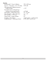
6 Technical data6 Technische Daten
STA 1000
Reflektormaß / Size of reflector: 1090 x 991 mm
Gewinn / Gain (bei / at 11.75 GHz): 40.5 dB
Öffnungswinkel (Halbwertsbreite) /
Angle of beam: < 1.8°
Kreuzpolarisationsentkopplung /
Isolation of cross-polarisation: > 27 dB
Mastschelle / Mounting of mast: 32 – 76 mm
Max. Elevation / Max. Elevation: 5° – 90°
F/D Verhältnis / F/D ratio: 0.55
Offsetwinkel / Angle of offset: 25°
Windlast / Wind load: 268 kg (bei / at 216 km/h)
Feedaufnahme / Mounting of feed: Ø 23 und / and 40 mm
STA 855
Reflektormaß / Size of reflector: Ø 850 mm
Gewinn / Gain (bei / at 11.75 GHz): 38.65 dB
Öffnungswinkel (Halbwertsbreite) /
Angle of beam: < 2.2°
Kreuzpolarisationsentkopplung /
Isolation of cross-polarisation: > 27 dB
Mastschelle / Mounting of mast: 32 – 76 mm
Max. Elevation / Max. Elevation: 15° – 50°
F/D Verhältnis / F/D ratio: 0.6
Offsetwinkel / Angle of offset: 21.5°
Windlast / Wind load: 192.1 kg (bei / at 216 km/h)
Feedaufnahme / Mounting of feed: Ø 23 und / and 40 mm

- 11 -
- 11 -
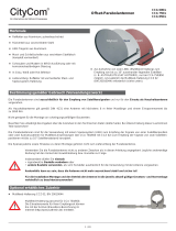
STA 755
Reflektormaß / Size of reflector: 740 x 840 mm
Gewinn / Gain (bei / at 11.75 GHz): 37.55 dB
Öffnungswinkel (Halbwertsbreite) /
Angle of beam: < 2.2°
Kreuzpolarisationsentkopplung /
Isolation of cross-polarisation: > 27 dB
Mastschelle / Mounting of mast: 32 – 50 mm
Max. Elevation / Max. Elevation: 15° – 50°
F/D Verhältnis / F/D ratio: 0.6
Offsetwinkel / Angle of offset: 25°
Windlast / Wind load: 156.2 kg (bei / at 216 km/h)
Feedaufnahme / Mounting of feed: Ø 23 und / and 40 mm

Änderungen vorbehalten. Technische Angaben ohne Gewähr.
03122018© by GSS Grundig Systems GmbH .E.O & .E atad lacinhceT .devreser snoitaretlA
Service:
Phone: +49 (0) 911 / 703 2221
Fax: +49 (0) 911 / 703 2326
Email: ser[email protected]
-
 1
1
-
 2
2
-
 3
3
-
 4
4
-
 5
5
-
 6
6
-
 7
7
-
 8
8
-
 9
9
-
 10
10
-
 11
11
-
 12
12


GSS STA 755 Assembly Instructions Manual
- Typ
- Assembly Instructions Manual
in anderen Sprachen
- English: GSS STA 755
Verwandte Artikel
Andere Dokumente
-
 CityCom CCA 850 Series Benutzerhandbuch
-
Kathrein Euroline KEA 650 Benutzerhandbuch
-
Kathrein 20010006 Benutzerhandbuch
-
Kathrein CAS 80ws Datenblatt
-
-
Kathrein CAS 90ws Benutzerhandbuch
-
-
-
-
Abicor Binzel PP PLUS ABIMIG AT LW Bedienungsanleitung
