Baumer OG 71 Installation and Operating Instructions
- Typ
- Installation and Operating Instructions

OG 71
Inkrementaler Drehgeber
Incremental encoder
Montage- und Betriebsanleitung
Mounting and operating instructions
MB077 - 11055686
Baumer_OG71_II_DE-EN (20A1)

Baumer_OG71_II_DE-EN (20A1)
MB077 - 11055686
Inhaltsverzeichnis
Inhaltsverzeichnis
1 Allgemeine Hinweise .......................................................................................................................................................... 1
2 Betrieb in explosionsgefährdeten Bereichen
................................................................................................... 3
3 Sicherheitshinweise
........................................................................................................................................................... 5
4 Vorbereitung
............................................................................................................................................................................ 7
4.1 Lieferumfang
............................................................................................................................................................... 7
4.2 Zur Montage erforderlich (nicht im Lieferumfang enthalten)
............................................................. 8
4.3 Erforderliches Werkzeug (nicht im Lieferumfang enthalten)
............................................................. 8
5 Montage
....................................................................................................................................................................................... 9
5.1 Direkte Montage
....................................................................................................................................................... 9
5.1.1 Schritt 1
...................................................................................................................................................................... 9
5.1.2 Schritt 2
...................................................................................................................................................................... 9
5.1.3 Schritt 3
....................................................................................................................................................................10
5.1.4 Schritt 4
....................................................................................................................................................................10
5.1.5 Schritt 5 und 6
.......................................................................................................................................................11
5.2 MitExzenterscheibenamServoansch
.....................................................................................................12
5.2.1 Schritt 1
....................................................................................................................................................................12
5.2.2 Schritt 2
....................................................................................................................................................................12
5.2.3 Schritt 3
....................................................................................................................................................................13
5.2.4 Schritt 4
....................................................................................................................................................................13
5.2.5 Schritt 5
....................................................................................................................................................................14
5.3 Maximal zulässige Montagefehler unter Verwendung der
Baumer Hübner Federscheibenkupplung K 35
......................................................................................15
6 Abmessung
.............................................................................................................................................................................16
7 Elektrischer Anschluss
..................................................................................................................................................16
7.1 Beschreibung der Anschlüsse
.........................................................................................................................16
7.2 Klemmenbelegung
.................................................................................................................................................17
7.3 Ausgangssignale
....................................................................................................................................................17
7.4 Sensorkabel HEK 8 (Zubehör)
........................................................................................................................17
8 Demontage
..............................................................................................................................................................................18
8.1 Direkte Montage
.....................................................................................................................................................18
8.2 MitExzenterscheibenamServoansch
.................................................................................................... 20
9 EU-Konformitätserklärung
.......................................................................................................................................... 22
10 Technische Daten
.............................................................................................................................................................. 23
10.1 Technische Daten - elektrisch
........................................................................................................................ 23
10.2 Technische Daten - mechanisch
................................................................................................................... 23
11 Zubehör
.................................................................................................................................................................................... 25

MB077 - 11055686
Baumer_OG71_II_DE-EN (20A1)
Table of contents
Table of contents
1 General notes .......................................................................................................................................................................... 2
2 Operation in potentially explosive environments
........................................................................................... 4
3 Security indications
............................................................................................................................................................ 6
4 Preparation
............................................................................................................................................................................... 7
4.1 Scope of delivery
...................................................................................................................................................... 7
4.2 Required for mounting (not included in scope of delivery)
................................................................. 8
4.3 Required tools (not included in scope of delivery)
.................................................................................. 8
5 Mounting
..................................................................................................................................................................................... 9
5.1 Direct mounting
......................................................................................................................................................... 9
5.1.1 Step 1
.......................................................................................................................................................................... 9
5.1.2 Step 2
.......................................................................................................................................................................... 9
5.1.3 Step 3
........................................................................................................................................................................10
5.1.4 Step 4
........................................................................................................................................................................10
5.1.5 Step 5 and 6
...........................................................................................................................................................11
5.2 Witheccentricdiskstothesynchroange
................................................................................................12
5.2.1 Step 1
........................................................................................................................................................................12
5.2.2 Step 2
........................................................................................................................................................................12
5.2.3 Step 3
........................................................................................................................................................................13
5.2.4 Step 4
........................................................................................................................................................................13
5.2.5 Step 5
........................................................................................................................................................................14
5.3 Maximum permissible mounting tolerance hen the
Baumer Hübner K 35 spring disk coupling is used
...............................................................................15
6 Dimension
................................................................................................................................................................................16
7 Electrical connection
.......................................................................................................................................................16
7.1 Terminalsignicance
............................................................................................................................................16
7.2 Terminal assignment
............................................................................................................................................17
7.3 Output signals
..........................................................................................................................................................17
7.4 Sensor cable HEK 8 (accessory)
...................................................................................................................17
8 Dismounting
...........................................................................................................................................................................18
8.1 Direct mounting
.......................................................................................................................................................18
8.2 Witheccentricdiskstothesynchroange
............................................................................................... 20
9 EU Declaration of Conformity
................................................................................................................................... 22
10 Technical data
.......................................................................................................................................................................24
10.1 Technical data - electrical ratings
..................................................................................................................24
10.2 Technical data - mechanical design
.............................................................................................................24
11 Accessories
........................................................................................................................................................................... 25

1
Baumer_OG71_II_DE-EN (20A1)
MB077 - 11055686
1 Allgemeine Hinweise
1 Allgemeine Hinweise
1.1 Zeichenerklärung:
Gefahr
Warnung bei möglichen Gefahren
Hinweis zur Beachtung
Hinweis zur Gewährleistung eines einwandfreien Betriebes des Gerätes
i
Information
Empfehlung für die Gerätehandhabung
1.2 Der inkrementale Drehgeber OG 71 ist ein opto-elektronisches Prä zi sionsmessgerät, das
mitSorgfaltnurvontechnischqualiziertemPersonalgehandhabtwerdendarf.
1.3 Die zu erwartende Lebensdauer des Gerätes hängt von den Kugellagern ab, die mit einer
Dauerschmierung ausgestattet sind.
1.4
Der Lagertemperaturbereich des Gerätes liegt zwischen -15 °C bis +70 °C.
1.5
Der Betriebstemperaturbereich des Gerätes liegt zwischen -20 °C bis +85 °C,
eingeschränkt im Ex-Bereich, siehe Abschnitt 2,
am Gehäuse gemessen.
1.6
EU-Konformitätserklärung gemäß den europäischen Richtlinien.
1.7 Das Gerät ist zugelassen nach UL (gilt nicht für Einsatz in explosionsgefährdeten Bereichen).
1.8 Wir gewähren 2 Jahre Gewährleistung im Rahmen der Bedingungen des Zentralverbandes der
Elektroindustrie (ZVEI).
1.9 Wartungsarbeiten sind nicht erforderlich. Das Gerät darf nur wie in dieser Anleitung beschrie-
ben geöffnet werden. Reparaturen, die ein vollständiges Öffnen des Gerätes erfordern, sind
ausschließlich vom Hersteller durchzuführen. Am Gerät dürfen keine Veränderungen vorge-
nommen werden.
1.10 Bei Rückfragen bzw. Nachlieferungen sind die auf dem Typenschild des Gerätes angege-
benen Daten, insbesondere Typ und Seriennummer, unbedingt anzugeben.
1.11
Entsorgung (Umweltschutz):
Gebrauchte Elektro- und Elektronikgeräte dürfen nicht im Hausmüll entsorgt werden.
DasProduktenthältwertvolleRohstoffe,dierecyceltwerdenkönnen.Wennimmer
möglich sollen Altgeräte lokal am entsprechenden Sammeldepot entsorgt werden. Im
BedarfsfallgibtBaumerdenKundendieMöglichkeit,Baumer-Produktefachgerechtzuentsor-
gen. Weitere Informationen siehe www.baumer.com.
i
Achtung!
BeschädigungdesaufdemGerätbendlichenSiegels führt zu Gewährleistungsver-
lust.

MB077 - 11055686
Baumer_OG71_II_DE-EN (20A1)
2
General notes 1
1 General notes
1.1 Symbol guide:
Danger
Warnings of possible danger
General information for attention
Informations to ensure correct device operation
i
Information
Recommendation for device handling
1.2 The incremental encoder OG 71 is an opto electro nic precision measurement device which
must be handled with care by skilled personnel only.
1.3 The expected service life of the device depends on the ball bearings, which are equipped with
a permanent lubrication.
1.4
The storage temperature range of the device is between -15 °C and +70 °C.
1.5
The operating temperature range of the device is between -20 °C and +85 °C,
restricted in potentially explosive environments, see section 2,
measured at the housing.
1.6
EU Declaration of Conformity meeting to the European Directives.
1.7 The device is UL approved (not applicable for operation in potentially explosive atmospheres).
1.8 We grant a 2-year warranty in accordance with the regulations of the ZVEI (Central Association
of the German Electrical Industry).
1.9 Maintenance work is not necessary. The device may be only opened as described in this
instruction. Repair work that requires opening the device completely must be carried out by the
manufacturer. Alterations of the device are not permitted.
1.10 In the event of queries or subsequent deliveries, the data on the device type label must be
quoted, especially the type designation and the serial number.
1.11
Disposal (environmental protection):
Do not dispose of electrical and electronic equipment in household waste. The product
contains valuable raw materials for recycling. Whenever possible, waste electrical and
electronic equipment should be disposed locally at the authorized collection point. If
necessary, Baumer gives customers the opportunity to dispose of Baumer products profession-
ally. For further information see www.baumer.com.
i
Warning!
Damaging the seal on the device invalidates warranty.

3
Baumer_OG71_II_DE-EN (20A1)
MB077 - 11055686
2 Betrieb in explosionsgefährdeten Bereichen
2 Betrieb in explosionsgefährdeten Bereichen (nur bei Option ATEX)
Das Gerät entspricht der Richtlinie 2014/34/EU für explosionsgefährdete Bereiche.
Der Einsatz ist gemäß den Gerätekategorien 3 G (Ex-Atmosphäre Gas) und 3 D (Ex-Atmo-
sphäre Staub) zulässig.
Gerätekategorie 3 G: - Ex-Kennzeichnung: II 3 G Ex nA IIC T4 Gc X
- Normenkonformität: EN 60079-0:2012 + A11:2013
EN 60079-15:2010
- Zündschutzart: nA
- Temperaturklasse: T4
- Gerätegruppe: II
Gerätekategorie 3 D: - Ex-Kennzeichnung: II 3 D Ex tc IIIC T85°C Dc X
- Normenkonformität: EN 60079-31:2014
- Schutzprinzip: Schutz durch Gehäuse
-Max.Oberächentemperatur:+85°C
- Gerätegruppe: III
Der Einsatz in anderen explosionsgefährdeten Bereichen ist nicht zulässig.
2.1 Besondere Bedingung:
Der maximale Umgebungstemperaturbereich für den Einsatz des Gerätes im Ex-Bereich
beträgt -20 °C bis +60 °C.
2.2 Der Anlagenbetreiber hat zu gewährleisten, dass eine mögliche Staubablagerung eine maxi-
male Schichtdicke von 5 mm nicht überschreitet (gemäß EN 60079-14).
2.3 Eine gegebenenfalls an anderen Stellen aufgeführte UL-Listung gilt nicht für den Einsatz im
Ex-Bereich.
2.4 Das Gerät darf nur in Betrieb genommen werden, wenn ...
– die Angaben auf dem Typenschild des Gerätes mit dem zulässigen Ex-Einsatzbereich vor
Ort übereinstimmen (Gerätegruppe, Kategorie, Zone, Temperaturklasse bzw. maximale
Oberächentemperatur),
– die Angaben auf dem Typenschild des Gerätes mit dem Spannungsnetz übereinstimmen,
– das Gerät unbeschädigt ist (keine Schäden durch Transport und Lagerung) und
– sichergestellt ist, dass keine explosionsfähige Atmosphäre, Öle, Säure, Gase, Dämpfe,
Strahlungen etc. bei der Montage vorhanden sind.
2.5 An Betriebsmitteln, die in explosionsgefährdeten Bereichen eingesetzt werden, darf keine
Veränderung vorgenommen werden. Reparaturen dürfen nur durch vom Hersteller autorisierte
Stellen ausgeführt werden. Bei Zuwiderhandlung erlischt die Ex-Zulassung.
2.6 Bei der Montage und Inbetriebnahme ist die Norm EN 60079-14 zu beachten.
Das Gerät ist entsprechend den Angaben in der Montage- und Betriebsanleitung zu
betreiben. Die für die Verwendung bzw. den geplanten Einsatzzweck zutreffenden
Gesetze, Richtlinien und Normen sind zu beachten.

MB077 - 11055686
Baumer_OG71_II_DE-EN (20A1)
4
Operation in potentially explosive environments 2
2 Operation in potentially explosive environments (only with option ATEX)
The device complies with the directive 2014/34/EU for potentionally explosive atmospheres.
It can be used in accordance with equipment categories 3 G (explosive gas atmosphere) and
3 D (explosive dust atmosphere).
Equipment category 3 G: - Ex labeling: II 3 G Ex nA IIC T4 Gc X
- Conforms to standard: EN 60079-0:2012 + A11:2013
EN 60079-15:2010
- Type of protection: nA
- Temperature class: T4
- Group of equipment: II
Equipment category 3 D: - Ex labeling: II 3 D Ex tc IIIC T85°C Dc X
- Conforms to standard: EN 60079-31:2014
- Protective principle: Protection by enclosure
- Max. surface temperature: +85 °C
- Group of equipment: III
The operation in other explosive atmospheres is not permissible.
2.1 Special condition:
In Ex areas the device must only be used within the ambient temperature range from -20 °C to
+60 °C.
2.2 The plant operator must ensure that any possible dust deposit does not exceed a thickness of
5 mm (in accordance with EN 60079-14).
2.3 An UL listing that may be stated elsewhere is not valid for use in explosive environments.
2.4 Operation of the device is only permissible when ...
– the details on the type label of the device match the on-site conditions for the permissible
Ex area in use (group of equipment, equipment category, zone, temperature class or maxi-
mum surface temperature),
– the details on the type label of the device match the electrical supply network,
– the device is undamaged (no damage resulting from transport or storage), and
– it has been checked that there is no explosive atmosphere, oils, acids, gases, vapors,
radiation etc. present when mounting.
2.5 It is not permissible to make any alteration to equipment that is used in potentially explosive en-
vironments. Repairs may only be carried out by authorized authorities provided by the manufac-
turer. Contravention invalidates the EX approval.
2.6 Attend the norm EN 60079-14 during mount and operation.
The device must be operated in accordance with the stipulations of the mounting and
operating instructions. The relevant laws, regulations and standards for the planned
application must be observed.

5
Baumer_OG71_II_DE-EN (20A1)
MB077 - 11055686
3 Sicherheitshinweise
3 Sicherheitshinweise
3.1 Verletzungsgefahr durch rotierende Wellen
Haare und Kleidungsstücke können von rotierenden Wellen erfasst werden.
• Vor allen Arbeiten alle Betriebsspannungen ausschalten und Maschinen stillsetzen.
3.2 Zerstörungsgefahr durch elektrostatische Auadung
DieelektronischenBauteileimGerätsindempndlichgegenhoheSpannungen.
• Steckkontakte und elektronische Komponenten nicht berühren.
• Ausgangsklemmen vor Fremdspannungen schützen.
• Maximale Betriebsspannung nicht überschreiten.
3.3 Zerstörungsgefahr durch mechanische Überlastung
Eine starre Befestigung kann zu Überlastung durch Zwangskräfte führen.
• Die Beweglichkeit des Gerätes niemals einschränken.
Unbedingt die Montagehinweise beachten.
• Die vorgegebenen Abstände und/oder Winkel unbedingt einhalten.
3.4 Zerstörungsgefahr durch mechanischen Schock
Starke Erschütterungen, z. B. Hammerschläge, können zur Zerstörung der Abtastung führen.
• Niemals Gewalt anwenden.
Bei sachgemäßer Montage lässt sich alles leichtgängig zusammenfügen.
• Für die Demontage geeignetes Abziehwerkzeug benutzen.
3.5 Zerstörungsgefahr durch Verschmutzung
Schmutz kann im Gerät zu Kurzschlüssen und zur Beschädigung der Abtastung führen.
• Während aller Arbeiten am Gerät auf absolute Sauberkeit achten.
• Niemals Öl oder Fett in das Innere des Gerätes gelangen lassen.
3.6 Zerstörungsgefahr durch klebende Flüssigkeiten
Klebende Flüssigkeiten können die Abtastung und die Kugellager beschädigen. Die Demontage
eines mit der Achse verklebten Gerätes kann zu dessen Zerstörung führen.
3.7 Explosionsgefahr (nur bei Option ATEX)
Das Gerät darf in explosiongefährdeten Bereichen der Kategorien 3 D und 3 G eingesetzt wer-
den. Der Betrieb in anderen explosionsgefährdeten Bereichen ist nicht zulässig.

MB077 - 11055686
Baumer_OG71_II_DE-EN (20A1)
6
Security indications 3
3 Security indications
3.1 Risk of injury due to rotating shafts
Hair and clothes may become tangled in rotating shafts.
• Before all work switch off all voltage supplies and ensure machinery is stationary.
3.2 Risk of destruction due to electrostatic charge
Electronic parts contained in the device are sensitive to high voltages.
• Do not touch plug contacts or electronic components.
• Protect output terminals against external voltages.
• Do not exceed maximum voltage supply.
3.3 Risk of destruction due to mechanical overload
Rigid mounting may give rise to constraining forces.
• Never restrict the freedom of movement of the device.
The mounting instructions must be followed.
• Itisessentialthatthespeciedclearancesand/oranglesareobserved.
3.4 Risk of destruction due to mechanical shock
Violent shocks, e. g. due to hammer impacts, can lead to the destruction of the sensing system.
• Never use force.
Mounting is simple when correct procedure is followed.
• Use suitable puller for dismounting.
3.5 Risk of destruction due to contamination
Dirt penetrating inside the device can cause short circuits and damage the sensing system.
• Absolute cleanliness must be maintained when carrying out any work on the device.
• Never allow lubricants to penetrate the device.
3.6 Risk of destruction due to adhesive uids
Adhesiveuidscandamagethesensingsystemandtheballbearings.Dismountingadevice,
secured to a shaft by adhesive may lead to the destruction of the device.
3.7 Explosion risk (only with option ATEX)
You can use the device in areas with explosive atmospheres of category 3 D and 3 G. The op-
eration in other explosive atmospheres is not permissible.

7
Baumer_OG71_II_DE-EN (20A1)
MB077 - 11055686
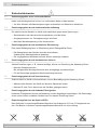
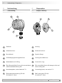
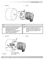
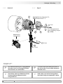
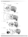
1
Gehäuse
2
Vollwelle ø6 mm
3
Servoansch
4
3x Befestigungsbohrung M4x6 mm
5
Abdeckhaube mit O-Ring
6
Ejot-Schraube M4x16 mm mit Innensechskant
und Schraubensicherung M4
7
Anschlussplatine, siehe Abschnitt 7.2.
8
EMV-KabelverschraubungPG9/11
für Kabel ø5...9 mm
1
Housing
2
Solid shaft ø6 mm
3
Synchroange
4
3xxingboreM4x6mm
5
Cover with o-ring
6
Ejot screw M4x16 mm with hexagon drive and
screw locking M4
7
Connecting board, see section 7.2.
8
EMCcableglandPG9/11
for cable ø5...9 mm
4 Vorbereitung
4.1 Lieferumfang
4 Preparation
4.1 Scope of delivery
4 Vorbereitung/Preparation
13
2
8
7 5
6
4

MB077 - 11055686
Baumer_OG71_II_DE-EN (20A1)
8
Vorbereitung/Preparation 4
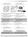
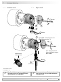
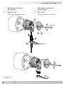
4.2 Zur Montage erforderlich
(nicht im Lieferumfang enthalten)
4.2 Required for mounting
(not included in scope of delivery)
9.1
Anbauvorrichtung mit Befestigungsschrauben,
für direkte Montage an das Gerät
(kundenspezisch)
9.2
Anbauvorrichtung mit Befestigungsschrauben,
für Montage mit Exzenterscheiben am
Servoansch(kundenspezisch)
10
Befestigungsschraube M4
11
Exzenterscheibe (Spannpratze), als Zubehör
erhältlich, Satz mit 3 Stück:
Bestellnummer 11081483
12
Befestigungsschraube M3
13
Federscheibenkupplung K 35,
als Zubehör erhältlich.
14
Sensorkabel HEK 8, als Zubehör erhältlich,
siehe Abschnitt 7.4.
9.1
Installationttingwithxingscrews,
for direct mounting to the device
(customized)
9.2
Installationttingwithxingscrews,
for mounting with eccentric disks to the syn-
chroange(customized)
10
Fixing screw M4
11
Eccentric disk (clamping claw), available as
accessory, set with 3 pieces:
Order number 11081483
12
Fixing screw M3
13
Spring disk coupling K 35,
available as accessory.
14
Sensor cable HEK 8, available as accessory,
see section 7.4.
4.3 Erforderliches Werkzeug
(nicht im Lieferumfang enthalten)
4.3 Required tools
(not included in scope of delivery)
3x
3x
3x
9.1 9.2
11
10
13
14
12
*
*
*
*
*
2,5 und 3 mm
20 mm
15
Werkzeugset als Zubehör erhältlich:
Bestellnummer 11068265
2.5 and 3 mm
20 mm
15
Tool kit available as accessory:
Order number 11068265

5 Montage / Mounting
9
Baumer_OG71_II_DE-EN (20A1)
MB077 - 11055686
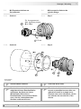
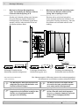
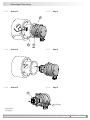
5 Montage
5.1 Direkte Montage
5.1.1 Schritt 1
5 Mounting
5.1 Direct mounting
5.1.1 Step 1
5.1.2 Schritt 2 5.1.2 Step 2
Zul. Anzugsmoment
Max. tightening torque
M
t
= 1 Nm
* Siehe Seite 8
See page 8
10
*
13
*
9.1
*
M4
2.5 mm

Montage / Mounting 5
MB077 - 11055686
Baumer_OG71_II_DE-EN (20A1)
10
* Siehe Seite 8
See page 8
5.1.4 Schritt 4 5.1.4 Step 4
Zul. Anzugsmoment
Max. tightening torque
M
t
= 2...3 Nm
5.1.3 Schritt 3 5.1.3 Step 3
Die Antriebswelle sollte einen
möglichst kleinen Rundlauffehler
aufweisen, da dieser zu einem
Winkelfehler führen kann.
Rundlauffehler verursachen Vibrati-
onen, die die Lebensdauer des
Gerätes verkürzen können.
The drive shaft should have as less
runout as possible because this can
otherwise result in an angle error.
Runouts can cause vibrations, which
can shorten the service life of the
device.
Antriebswelle einfetten. Lubricate drive shaft.
13
*
2.5 mm

5 Montage / Mounting
11
Baumer_OG71_II_DE-EN (20A1)
MB077 - 11055686
6
*
5
*
8
*
Kabelschirm
Cable shield
Ansicht X siehe Abschnitt 7.2.
View X see section 7.2.
5.1.5 Schritt 5 und 6 5.1.5 Step 5 and 6
Zul. Anzugsmoment
Max. tightening torque
M
t
= 3 Nm
Zur Gewährleistung der angegebenen
Schutzart sind nur geeignete Kabel-
durchmesser zu verwenden.
To ensure the specied protection of
the device the correct cable diameter
must be used.
14
*
ø5...9 mm
* Siehe Seite 7 oder 8
See page 7 or 8
7
*
3 mm
20 mm

Montage / Mounting 5
MB077 - 11055686
Baumer_OG71_II_DE-EN (20A1)
12
Zul. Anzugsmoment
Max. tightening torque
M
t
= 1 Nm
13
*
11
*
12
*
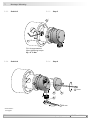
5.2 Mit Exzenterscheiben am
Servoansch
5.2.1 Schritt 1
5.2 With eccentric disks to the
synchro ange
5.2.1 Step 1
5.2.2 Schritt 2 5.2.2 Step 2
9.2
*
Die Antriebswelle sollte einen
möglichst kleinen Rundlauffehler
aufweisen, da dieser zu einem
Winkelfehler führen kann.
Rundlauffehler verursachen Vibrati-
onen, die die Lebensdauer des
Gerätes verkürzen können.
The drive shaft should have as less
runout as possible because this can
otherwise result in an angle error.
Runouts can cause vibrations, which
can shorten the service life of the
device.
Antriebswelle einfetten. Lubricate drive shaft.
* Siehe Seite 8
See page 8
M3
2.5 mm

5 Montage / Mounting
13
Baumer_OG71_II_DE-EN (20A1)
MB077 - 11055686
Zul. Anzugsmoment
Max. tightening torque
M
t
= 2...3 Nm
5.2.3 Schritt 3 5.2.3 Step 3
5.2.4 Schritt 4 5.2.4 Step 4
6
*
* Siehe Seite 7
See page 7
13
*
5
*
8
*
2.5 mm
3 mm
20 mm

Montage / Mounting 5
MB077 - 11055686
Baumer_OG71_II_DE-EN (20A1)
14
5.2.5 Schritt 5 5.2.5 Step 5
Ansicht X siehe Abschnitt 7.2.
View X see section 7.2.
Zul. Anzugsmoment
Max. tightening torque
M
t
= 3 Nm
6
*
5
*
8
14
*
*
ø5...9 mm
Zur Gewährleistung der angegebenen
Schutzart sind nur geeignete Kabel-
durchmesser zu verwenden.
To ensure the specied protection of
the device the correct cable diameter
must be used.
* Siehe Seite 7 oder 8
See page 7 or 8
7
*
i
Wir empfehlen, das Gerät so zu
montieren, dass der Kabelanschluss
keinem direkten Wassereintritt
ausgesetzt ist.
i
It is recommended to mount the device
with cable connection facing down-
ward and being not exposed to water.
Kabelschirm
Cable shield
20 mm
3 mm

5 Montage / Mounting
15
Baumer_OG71_II_DE-EN (20A1)
MB077 - 11055686
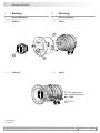
5.3 Maximal zulässige Montagefehler
unter Verwendung der Baumer Hübner
Federscheibenkupplung K 35
Geräte mit Vollwelle sollten unter Verwen-
dung der Baumer Hübner Federschei-
benkupplung K 35 (Zubehör) angetrieben
werden, die sich ohne axialen Druck auf
die Welle schieben lässt.
5.3 Maximum permissible mounting toler-
ance hen the Baumer Hübner K 35
spring disk coupling is used
Devices with a solid shaft should be
driven through the Baumer Hübner K 35
spring disk coupling (accessory), that can
be pushed onto the shaft without axial
loading.
F
max
= 10N
ZulässigerParallelversatz
Admissible parallel misalignment
Zulässiger Winkelfehler
Admissible angular error
Zulässige Axialbewegung
Admissible axial movement
±0.2 (±0.05*)
±1°
* Mit isolierender Kunststoffnabe
With insulated hub
±0.7 (±0.3*)
Die Montage an den Antrieb muss mit
möglichst geringem Winkelfehler und
Parallelversatz erfolgen.
Das harte Aufschlagen von Kupp-
lungsteilen auf die Welle ist wegen der
Gefahr von Kugellagerbeschädi-
gungen nicht zulässig.
The device must be mounted on the
drive with the least possible angular
error and parallel misalignment.
Coupling components must not be
driven onto the shaft with improper
force (e. g. hammer impacts), because
of the risk of damaging the ball
bearings.
Alle Abmessungen in Millimeter (wenn nicht anders angegeben)
All dimensions in millimeters (unless otherwise stated)

MB077 - 11055686
Baumer_OG71_II_DE-EN (20A1)
16
Abmessung - Elektrischer Anschluss/Dimension-Electricalconnection 6-7
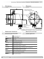
6 Abmessung
(73136)
6 Dimension
(73136)
Drehrichtung positiv
Positive rotating direction
7 Elektrischer Anschluss
7.1 Beschreibung der Anschlüsse
7 Electrical connection
7.1 Terminal signicance
Ansicht X
siehe Abschnitt 7.2.
View X
see section 7.2.
M4x6 tief/deep
+UB; +
Betriebsspannung
Voltage supply
; ; GND; 0V
Masseanschluss
Ground
;
Erdungsanschluss (Gehäuse)
Earth ground (housing)
A; K1; A+
Ausgangssignal Kanal 1
Output signal channel 1
A
; K1; A-
Ausgangssignal Kanal 1 invertiert
Output signal channel 1 inverted
B; K2; B+
Ausgangssignal Kanal 2 (90° versetzt zu Kanal 1)
Output signal channel 2 (offset by 90° to channel 1)
B
; K2; B-
Ausgangssignal Kanal 2 invertiert
Output signal channel 2 inverted
C; K0; R; R+
Nullimpuls (Referenzsignal)
Zero pulse (reference signal)
C
; K0; R; R-
Nullimpuls invertiert
Zero pulse inverted
Alle Abmessungen in Millimeter (wenn nicht anders angegeben)
All dimensions in millimeters (unless otherwise stated)

17
Baumer_OG71_II_DE-EN (20A1)
MB077 - 11055686
+
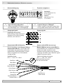
7 Elektrischer Anschluss/Electricalconnection
7.3 Ausgangssignale 7.3 Output signals
Signalfolge bei positiver
Drehrichtung, siehe Abschnitt 6.
Sequence for positive rotating
direction, see section 6.
7.4 Sensorkabel HEK 8 (Zubehör)
Es wird empfohlen, das Baumer Hübner
Sensorkabel HEK 8 zu verwenden oder
ersatzweise ein geschirmtes, paarig ver-
seiltes Kabel. Das Kabel sollte in einem
Stück und getrennt von Stromkabeln
verlegt werden.
Kabelabschluss:
HTL:1...3kΩ,TTL:120Ω
7.4 Sensor cable HEK 8 (accessory)
Baumer Hübner sensor cable HEK 8 is
recommended. As a substitute a shielded
twisted pair cable should be used.
Continuous wiring without any splices or
couplings should be used. Separate signal
cables from power cables.
Cable terminating resistance:
HTL:1...3kΩ,TTL:120Ω
Aderendhülsen benutzen.
Use core-end ferrules.
Rot/Red = +UB
Weiß/White = A
Braun/Brown = A
Grün/Green = B
Grau/Grey = C
Rosa/Pink = C
Gelb/ Yellow = B
Kabelschirm
Cable shield
Blau/Blue =
Schwarz/Black = ---
Violett/Violet = ---
7.2 Klemmenbelegung 7.2 Terminal assignment
Ansicht X
siehe Abschnitt 5.1.6,
5.2.5 und 6.
View X
see section 5.1.6,
5.2.5 and 6.
Betriebsspannung nicht auf Ausgänge
legen! Zerstörungsgefahr!
Spannungsabfälle in langen Leitungen
berücksichtigen (Ein- und Ausgänge).
Do not connect voltage supply to
outputs! Danger of damage!
Please, beware of possible voltage drop
in long cable leads (inputs and outputs).
nur/only TTL
A
A
B
B
C
C
90°
Seite wird geladen ...
Seite wird geladen ...
Seite wird geladen ...
Seite wird geladen ...
Seite wird geladen ...
Seite wird geladen ...
Seite wird geladen ...
Seite wird geladen ...
-
 1
1
-
 2
2
-
 3
3
-
 4
4
-
 5
5
-
 6
6
-
 7
7
-
 8
8
-
 9
9
-
 10
10
-
 11
11
-
 12
12
-
 13
13
-
 14
14
-
 15
15
-
 16
16
-
 17
17
-
 18
18
-
 19
19
-
 20
20
-
 21
21
-
 22
22
-
 23
23
-
 24
24
-
 25
25
-
 26
26
-
 27
27
-
 28
28


Baumer OG 71 Installation and Operating Instructions
- Typ
- Installation and Operating Instructions
in anderen Sprachen
- English: Baumer OG 71
Verwandte Artikel
-
Baumer HOGS 75 Installation and Operating Instructions
-
-
-
-
-
Baumer OG 9 Installation and Operating Instructions
-
-
-
-