Proosten Electronics Profline LBC 500 Benutzerhandbuch
- Typ
- Benutzerhandbuch

LBC 500
So ftw a re V1. 2
Typ e s :
LB C 512- 10
LB C 524- 5
Gebruiksaanwijzing - NL
Pa g ina 2
Users manual - GB
Pa ge 13
Gebrauchsanweisung – DE
Se ite 23

2
Nederlands
INTROD UCT IE
Op bladzijde 36 vindt u de specificaties van de LBC 500 serie.
De LBC 500 is een volledig automatische acculader en druppellader in één en kan
daarom permanent aan de netspanning en aan de accu aangesloten blijven. De
microprocessor controleert continu de accu en het laadproces zodat een zeer
veilig en nauwkeurig laadproces gewaarborgd wordt. De interne elektronica is
voortgekomen uit de modernste ontwikkelingen waardoor een bijzonder
intelligente lader is ontstaan.
De LBC 500 is te gebruiken voor een grote diversiteit aan lood accu’s, waaronder
Start, Semi-tractie, Vol-tractie, GEL, AGM, Calcium en Spiral.
De lader is voor vele accu’s geschikt omdat de laadspanning instelbaar is. Zie
hiervoor hoofdstuk ‘LADER INSTELLEN’, alinea ‘laadspanningen’.
Tijdens het laadproces, maar ook als de lader in druppellaadfase staat, mogen
eventuele gebruikers aan staan. De lader zal dan indirect als voeding dienen voor
de aangesloten apparatuur. Zo wordt de accu ontzien. Houdt er echter wel
rekening mee dat bij het laden van een (gedeeltelijk) lege accu de stroomafname
van de verbruikers ten kosten gaat van de laadstroom voor het laden van de accu.
Wilt u de acculader alleen (indirect) als voeding gebruiken, schakel de lader dan
in de voedingstand, zie hoofdstuk ‘LADER INSTELLEN’ alinea ‘lader als voeding’.
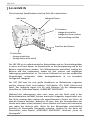
2 functies:
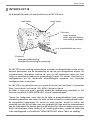
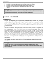
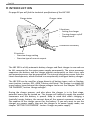
- Weergave laadinstelling
- Weergave foutmelding bij oproeping
Lader status
Laad status
3 functies:
- Lader instellen
- Lader aan/uitschakelen
- Foutmelding oproepen
Aansluitkabel naar accu

3
Nederlands
Het is voor de LBC lader geen probleem als er meerdere voedingsbronnen,
bijvoorbeeld een zonnepaneel, gelijktijdig aangesloten zijn.
Voor open lood accu’s (semi-tractie/vol-tractie) die zwaar cyclisch (veelvuldig
diep ontladen) gebruikt worden bestaat de mogelijkheid om een extra laadfase in
te schakelen. Neem hiervoor contact met ons op.
EIGENSCH APP E N
De LBC 500 heeft een groot aantal eigenschappen en beveiligingen ter
bevordering van de gebruiksvriendelijkheid, maar uiteraard om u ervan te
verzekeren dat het laadproces uitermate veilig verloopt.
Ompoling
Bij ompoling zijn de aansluitdraden voor de plus en de min met elkaar verwisseld
op de accu. De LBC 500 is geheel beveiligd tegen ompoling. De lader zal niet in
werking treden en de “power” indicatie zal rood oplichten. Verbreek de
verbinding en sluit de accu correct aan.
Kortsluiting op de uitgang
De lader is beveiligd tegen kortsluiting, ook als de netspanning aanwezig is. De
‘power’ indicatie zal hierbij rood oplichten.
Accu’s kunnen daarentegen niet tegen kortsluiting!
Maak daarom nooit een kortsluiting op de accu. Maak ook nooit een kortsluiting
als de lader is aangesloten op de accu, ongeacht of de netspanning aanwezig is.
Als een accu wordt kortgesloten bestaat er de kans dat de accu explodeert!!! Ook
de lader loopt dan ernstige beschadigingen op.
Temperatuur
Aangezien de LBC 500 geen ventilator heeft, is de lader afhankelijk van zijn
warmte afgifte via de behuizing (passieve koeling). Mocht de interne temperatuur
te hoog oplopen dan zal de lader de laadstroom terugregelen. Heeft dit
onvoldoende resultaat en blijft de temperatuur oplopen dan wordt de lading
gepauzeerd. De ‘power’ indicatie zal rood gaan branden. Als de lader voldoende
is afgekoeld zal het laadproces automatisch hervat worden en de ‘power’
indicatie weer groen op gaan lichten. Het verloop van deze beveiliging is sterk
afhankelijk van de omgevingstemperatuur.
Temperatuur sensor bewaking
Ook de temperatuurbeveiliging zoals hierboven omschreven wordt beveiligd.
Mocht namelijk de lader geen interne temperatuurmetingen kunnen verrichten
door een defecte temperatuur sensor, dan zal de lader niet functioneren en de
‘power’ indicatie rood oplichten. Op deze wijze is de lader maximaal beveiligd
tegen oververhitting.

4
Nederlands
Sofstart
Zowel de ingang als de uitgang bevat een softstart. Op deze manier heeft de lader
geen invloed op de DC en AC systemen.
Ingangspanning beveiliging
Mocht er een fout optreden op de ingang, dan zal de lader beveiligd worden
d.m.v. een glaszekering. Deze is bereikbaar via de onderplaat van de acculader,
vlak bij de ingangaansluiting van de lader. Bij vervanging dient er altijd een
zekering geplaatst te worden met dezelfde waarde als het origineel. Zie
technische specificaties op pagina 36.
Ingangspanning bewaking
Als de netspanning onder de 180VAC raakt zal de lader zich beveiligingen en de
lading pauzeren. Hierbij zal de ‘power’ indicatie rood oplichten. De lading zal
weer worden hervat als de spanning is opgelopen tot min. 190VAC.
Compensatie spanningsverlies
De acculader compenseert automatisch het spanningsverlies over de laadkabels.
Hierdoor wordt een correcte laadspanning gewaarborgd. Deze compensatie is
geoptimaliseerd voor de standaard kabellengte van 1mtr. Om een goede werking
te kunnen garanderen is het van belang dat de laadkabel daarom bij voorkeur
niet verlengt of verkort wordt.
Stroombegrenzing
De lader is voorzien van een stroombegrenzing.
Laadtijd bewaking
Alle fases van het laadproces zijn tijd bewaakt, maar in het bijzonder de eerste
laadfase, de hoofdlading. Mocht deze fase langer duren dan 14uur dan zal de
lading stoppen en de ‘power’ indicatie rood oplichten. Belangrijkste noodzaak
hiervan is dat zo voorkomen kan worden dat een kapotte accu doorgeladen blijft
worden. Maar uit deze bewaking kan ook blijken dat de lader niet passend is voor
de specifieke situatie. De laadstroom staat bijvoorbeeld in onjuiste verhouding
tot de accucapaciteit (de accu loopt schade op als het laadproces te lang duurt) of
door aanwezigheid van grote gebruikers blijft er onvoldoende laadstroom over
voor het laden van de accu.
Beschermingsgraad
De aanduiding om beschermingsgraad aan te geven bestaat uit de kenletters ‘IP’
(International Protection), gevolgd door twee of drie kengetallen die aangeven
aan welke voorwaarde er is voldaan. Het eerste cijfer heeft betrekking op de
beschermingsklasse stofdichtheid, het tweede cijfer op de vloeistofdichtheid en
het derde cijfer heeft betrekking op de slagvastheid. Aan de LBC 500 kan IP 205
worden toegekend. Dit betekent:

5
Nederlands
2 = de lader is beschermd tegen vaste stoffen groter dan 12mm.
0 = de lader heeft geen bescherming tegen water/vloeistof e.d.
5 = de lader kan een slagkracht verdragen van max. 2,00 Joule
(2Nm)
Belangrijk
Bescherm de lader voor vocht en vervuiling. Dit kan intern schade aanbrengen.
Eventuele reparatiekosten vallen dan niet onder de garantie.
LADER IN ST ELL E N
Laadspanningen
De LBC 500 beschikt over verschillende laadspanningen omdat elk accutype
andere voltages benodigd om de langste levensduur te kunnen garanderen. De
juiste laadspanningen dienen daarom vooraf ingesteld te worden door middel
van de power/mode drukknop. De acculader mag reeds aangesloten zijn, maar dit
is geen vereiste.
n
Sluit de lader aan op de netspanning. Druk direct hierna, binnen 5 seconden, op
de ‘power/mode’ knop. De lader staat nu in zijn instelmodus. Door het
herhaaldelijk drukken kunt u kiezen tussen de 4 LED’s bij ‘settings’. Bij elke setting
hoort een andere laadspanning, zie technische specificaties op pagina 36. Het
schema op de volgende pagina is een richtlijn. Raadpleeg echter altijd de
gegevens van uw accu of de geadviseerde laadspanningen passend zijn.
Aangezien vooral AGM accu’s een grote diversiteit aan laadspanningen hebben, is
het zeker in dit geval extra belangrijk om de geadviseerde laadspanning te
controleren.
Stel de lader nooit naar eigen inzicht in. Dit kan leiden tot onherstelbare schade
aan de accu.
Belangrijk
De lader kan alleen in de instelmodus gezet worden na aansluiting op de
netspanning. Als de lader bijvoorbeeld uit de stand-by gehaald wordt, is de lader
niet in te stellen.

6
Nederlands
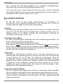
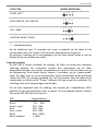
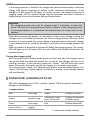
ACCUTYPE
ADVIES INSTELLING
START, NAT *
SEMI-TRACTIE, VOL-TRACTIE
GEL, AGM¹
CALCIUM, AGM², SPIRAL
* = fabrieksinstelling
Als de drukknop voor 10 seconde niet meer is gebruikt zal de lader uit de
instelmodus keren. De ‘power’ LED zal hierbij tweemaal kort knipperen.
De gekozen instelling zal in het geheugen van de lader blijven staan en zal op
blijven lichten als de lader aan staat.
Lader als voeding
De LBC 500 is tevens instelbaar als voeding. De lader zal hierbij één constante
spanning afgeven. De verbruikers kunnen dan rechtstreeks op de lader
aangesloten worden, dus zonder tussenkomst van de accu. Sluit de lader aan op
de netspanning. Druk direct hierna, binnen 5 seconden, op de ‘power/mode’
knop. De lader staat nu in zijn instelmodus. Druk herhaaldelijk op de drukknop
totdat alle LED’s bij ‘settings’ gedoofd zijn. Na 10 seconden keert de lader uit de
instelmodus en hierbij zal de “Power” indicatie LED twee maal kort oplichten. De
instelling staat nu in het geheugen van de lader.
Als de lader ingesteld staat als voeding, dan worden de 3 laadindicatie LED’s
gebruikt om de stroomafname weer te geven. Zo kan bepaald worden hoeveel
stroom de LBC 500 aan het leveren is.
LED Stroomafname
Groen, knippert 0%
Groen 1% - 20%
Groen + geel 21% - 40%
Geel 41% - 60%
Geel + rood 61% - 80%
Rood 81% - 100%
Rood, knippert > 100%
1 2 3 4
1 2 3 4
1 2 3 4
1 2 3 4
*

7
Nederlands
INST AL LATI E
De laadomgeving
Het laden van de accu moet in een geventileerde ruimte geschieden, daar er
explosieve gassen (knalgas) vrij kunnen komen uit de accu. Er dient altijd
voldoende vrije ruimte rondom de lader aanwezig te zijn (eventuele
ventilatieopeningen mogen niet geblokkeerd zijn). Dit is belangrijk voor
voldoende luchtcirculatie, t.b.v. de koeling van de lader en de afvoer van vrij
gekomen gassen. De LBC 500 is niet geschikt voor buitenshuis gebruik.
Belangrijk
Tijdens lekken of verdampen van brandstof niet laden.
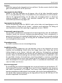
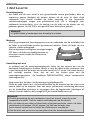
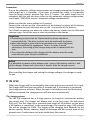
Montage
Met de geïntegreerde bevestigingsvoet aan de onderzijde van de acculader kan
de lader in verschillende posities gemonteerd worden. Plaats de lader op een
stabiele, vlakke ondergrond.
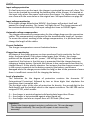
Met de optioneel verkrijgbare montage beugels
PC1 kunt u de lader eenvoudig plaatsen en
uitnemen zonder steeds de schroeven te
verwijderen.
Aansluiting met accu
In verband met de spanningscompensatie raden wij ten zeerste aan om de
bestaande kabellengte te houden. Mocht u toch de kabels willen verkorten, dan
is het belangrijk dat de lengte niet minder wordt als 0,7 meter. De kabels kunnen
wel verlengt worden, maar dat zal wel ten kosten gaan van de
spanningscompensatie. Zie hoofdstuk ‘EIGENSCHAPPEN’, alinea ‘compensatie
spanningsverlies’.
Zorg ervoor dat de lader van de netspanning afgekoppeld is.
Plaats de rode kabel d.m.v. de krokodillenklem op de pluspool van de accu en de
zwarte kabel op de minpool. Voor een vaste, permanente aansluiting adviseren
wij de krokodillen klemmen te vervangen door de bijgeleverde kabelogen of
vorkjes. Knip de kabel zo dicht mogelijk bij de krokodillenklemmen af.
Belangrijk
De accu aansluiting die niet verbonden is met het chassis, moet als eerste
aangesloten worden. Sluit de andere verbinding aan op het chassis.
Als u de lader op een stalen of aluminium schip gaat monteren, dient u de lader
geïsoleerd op te hangen. Dit wil zeggen, het huis van de lader mag
geen contact maken met het schip, om elektrolyse te voorkomen.
Sluit de lader aan op de accu op een afstand van de brandstofinstallatie.

8
Nederlands
Tip
Als extra beveiliging kunt u een zekering monteren in de + kabel. Gebruik
hiervoor een zekering die een stap zwaarder is dan de laadstroom van de lader.
Na installatie en instelling van de laadspanningen, is de lader klaar voor gebruik.
IN G EB RUIK
Wordt de lader op de netspanning aangesloten en maakt men geen gebruik van
de instelprocedure dan zal na 5 seconden de lader tweemaal kort knipperen en,
bij aanwezigheid van een accu, het laadproces aanvangen. Indien de lader reeds
aan staat en de accu wordt aangesloten, dan zal het laadproces direct aanvangen.
Het laadproces
De LBC 500 heeft standaard een viertal (laad)fases om de accu op een juiste
manier te laden en te onderhouden. De lader zal altijd in de hoofdlading (rode
LED) starten. Deze eerste laadfase heeft een minimale tijdsduur van 30 minuten,
dus ook bij aansluiting van een volle accu. In de tweede fase, de nalading (LED
geel), wordt de accu tot 100% volgeladen. De duur van het totale laadproces is
afhankelijk van de accukwaliteit, accucapaciteit, diepte van ontlading en van de
eventuele aanwezigheid van verbruikers die nog stroom vragen. Verder kunnen
eventuele foutmeldingen het laadproces ook vertragen.
Als het laadproces is voltooid zal de lader in de druppellaadstand (LED groen)
schakelen en de accu van een zogenaamde onderhoudslading voorzien. Mocht de
lader voor 24 uur in de druppelstand blijven bij een zeer geringe stroom, dan
schakelt de lader naar de ‘Jogging’ functie. Deze jogging functie is speciaal voor
accu’s die voor langere tijd weggezet worden, bijvoorbeeld tijdens een
winterstalling.
Belangrijk
Het laadproces mag alleen beëindigd worden als de groene LED van het
laadproces oplicht of knippert. Indien de lading tussentijds wordt onderbroken
kan de accu zijn spanning en zuur verhouding verliezen. Hierdoor kan er
schade ontstaan aan de accu.
Als de accu losgekoppeld wordt, de netspanning verbroken wordt of als de lader
in de stand-by stand geschakeld wordt, dan zal het huidige laadproces stoppen.
Indien er weer een accu aansloten wordt, de netspanning weer aanwezig is of de
lader weer geactiveerd wordt, dan zal in alle gevallen een nieuw laadproces
gestart worden.

9
Nederlands
Mocht er bij de start of tijdens van het laadproces een fout geconstateerd
worden, dan zal alleen de ‘power’ indicatie LED rood oplichten. De overige
indicatie LED’s zijn gedoofd. Raadpleeg de probleemoplosser voor de eventuele
handelingen.
Lader aan-/uitschakelen
Met de drukknop ‘power/mode’ aan de voorzijde van de lader, kan de lader
uitgeschakeld worden. Als deze knop 2 seconden ingedrukt wordt, schakelt de
lader in de stand-by functie. In deze stand-by modus zal de “Power” indicatie LED
telkens om de 10 seconden 2x kort oplichten. Tijdens de stand-by periode zal de
lader in zijn energie zuinige stand staan. Om de lader weer te activeren dient de
power/mode knop kort ingedrukt te worden. De ‘power’ LED zal weer groen
oplichten. Bij aanwezigheid van een accu zal direct een nieuw laadproces gestart
worden.
WE ER G AVE (LAAD)STAT US
Met de indicatie LED’s onder ‘charge process’ en ‘power’ is de status van de lader
af te lezen. Hierbij hebben de LED’s de volgende betekenis:
Charge process
LED’s
:
Power
LED
:
Rood Hoofdlading Licht groen op Lader aan
Geel Nalading
K
nippert
om 10sec
2x
groen
Lader gedeactiveerd
(stand
-
by stand
)
Groen Druppellading Licht rood op Foutmelding*
Groen, knippert Jogging
* = zie probleemoplosser

10
Nederlands
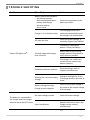
PROBL E EMOPL O SSER
Probleem (mogelijke) oorzaak Reden/Handeling
De ‘power’ LED licht
rood op.
*
Aansluit probleem:
- Geen accu aanwezig.
- Slechte verbinding tussen
lader en accu
- Ompoling.
- Kortsluiting.
Controleer de verbinding naar
de accu op fouten.
De lader staat in een
thermische stop.
Lading gepauzeerd.
Lader hervat het laadproces
automatisch als deze voldoen-
de is afgekoeld. Controleer de
ventilatie van de lader.
AC ingang te laag.
Controleer de netspanning.
Deze dient hoger als 180VAC
te zijn.
De hoofdlading duurt langer
dan 14uur.
De accu is stuk/slecht. Meet de
zuurgraad en vervang de accu
indien nodig.
Er staan zware verbruikers
aangesloten op de accu.
Schakel zo veel mogelijk
verbruikers uit tijdens het
laden of sluit een zwaardere
lader aan.
De lader heeft onvoldoende
laadstroom voor de betref-
fende accucapaciteit.
Hardware/software probleem
Stuur de lader retour naar de
leverancier/ fabrikant.
Waarschuwing voor een te
lage accuspanning.
Indicatie blijft gedurende
3min. oplichten. Het
laadproces zal wel gewoon
opstarten.
Accuspanning te hoog.
Lading gestaakt.
Controleer of de systeem
-
spanning overeen komt met de
uitgangspanning van de lader.
Er is een accu aangesloten,
maar de lader werkt niet goed
(eventueel vertonen ook de
LED’s onjuist gedrag).
Lader staat in de voeding
functie.
Raadpleeg hoofdstuk ‘LADER
INSTELLEN’ voor de juiste
setting.
>>>

11
Nederlands
* = als de power LED rood oplicht kan men door het kortstondig drukken op de
‘power/mode’ knop de betreffende foutmelding opvragen. Door middel van de 4
LED’s bij ‘settings’ zal afgelezen kunnen worden welke fout er geconstateerd is.
Zie overzicht op pagina 35. Raadpleeg tevens de uitleg onder de betreffende
alinea van het hoofdstuk ‘Eigenschappen’.
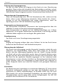
OND ERH OUD
De LBC lader behoeft geen specifiek onderhoud. Als u de lader schoon wilt
maken, gebruik dan enkel een (droog gewrongen) doek. Volg de instructies van
de fabrikant voor gebruik van en omgang met de accu. WAARSCHUWING:
Een accu bevat bijtend zwavelzuur.
Belangrijk
Controleer regelmatig de status van de acculader.
Controleer regelmatig de verbinding tussen lader en accu.
Vervang beschadigde kabels direct.
Controleer de ventilatie openingen regelmatig.
Controleer het vloeistofniveau bij een niet onderhoudsvrije accu regelmatig.
Het accuzuur (elektrolyt) dient +/- 1cm boven de platen uit komen. Gebruik
hiervoor alleen gedestilleerd of gedenatureerd water.
Er is een accu op de lader
aangesloten maar de lader
werkt geheel niet.
Er branden géén LED’s.
Geen ingangsspanning
aanwezig.
Controleer de netspanning.
Ingangszekering defect.
Vervang de ingangzekering. Of
Retourneer de lader naar de
dealer/ fabrikant.
Laadstatus geeft rood aan
(hoofdlading) maar de lader
levert niet zijn maximale
stroom.
Lader voelt warm.
Laadstroom is gereduceerd
i.v.m. interne temperatuur.
Laadstroom wordt hersteld als
de interne temperatuur
voldoende gedaald is.
Accu neemt geen stroom
meer op.
Accu gesulvateerd. Controleer
de accu.
Accu was reeds vol bij
aanschakeling van de lader en
deze zal snel naar de volgende
laadfase omschakelen.
Het laadproces is voltooid,
maar de accu is niet vol.
Accu gesulvateerd. Controleer de accu.

12
Nederlands
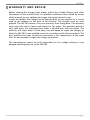
GAR ANT IE EN R EP AR ATIE
Raadplaag altijd eerst de probleemoplosser en de overige uitleg in deze
gebruiksaanwijzing voordat u de lader retourneert. Indien een defect/probleem
door middel van deze gebruiksaanwijzing opgelost had kunnen worden, dan zijn
wij genoodzaakt om de gemaakte kosten door te berekenen.
In geval van een defect kunt u de lader terug brengen naar uw leverancier of
rechtstreeks retourneren naar het adres op de achterzijde. De lader dient
gefrankeerd op gestuurd te worden. Op de LBC 500 serie wordt 5 jaar garantie
verleend vanaf verkoopdatum en alleen op de onderdelen en arbeidsloon van de
reparatie. Garantieduur is alleen van kracht als bij reparatie de (kopie)
aankoopbon overhandigd is. De garantie vervalt bij reparatiewerken door derden,
alsook door foutief gebruik of aansluiting van de lader. Er mogen alleen
werkzaamheden uitgevoerd worden om de interne (ingangs-) glaszekering te
vervangen. Probeer onder geen geding de lader zelf te repareren.
De fabrikant stelt zich niet aansprakelijk voor de laadspanninginstellingen of
schade als gevolg van gebruik van de LBC 500.

English
13
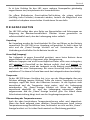
INTROD UCT IO N
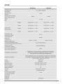
On page 36 you will find the technical specifications of the LBC 500.
The LBC 500 is a fully automatic battery charger and float charger in one and can
be left connected to the mains power supply permanently. The micro processor
supervises the battery and the charge process continuously so that a very safe
and accurate process can be guaranteed. The internal electronics comes from the
latest developments, which resulted in a exceptionally intelligent battery charger.
The LBC 500 can be used for a large diversity of battery types, such as Starting,
semi-traction, traction, GEL, AGM, Calcium and Spiral. The charger is suitable for
many battery types because the charge voltages can be set. See chapter ‘SETTING
THE CHARGER’, section ‘charge voltages’.
During the charge process, and also when the charger is in its float stage,
potential users may be turned on. The charger will indirectly supply the present
consumers and the battery is spared. Keep in mind that when charging a
(partially) empty battery, the current draw of the present consumers comes at
the expense of the charge current for the battery. If you only want to use the
charger as a power supply, then put the charger in its power supply mode, see
chapter ‘SETTING THE CHARGER’ section ‘charger as power supply’.
2 functions
:
- Overview charge setting
- Overview type of error at request
Charger
status
Charge
status
3 funct
ions
:
- Setting the charger
- Turning charger on/off
- Request error
Conn
ection to battery

14
English
You can use multiple power sources, like solar panels or a dynamo, together with
the LBC 500 battery charger.
For conventional open lead batteries (semi-traction and traction) that will be
heavily discharged on a regular base, a extra charge phase can be activated.
Contact us for this possibility.
FEAT UR ES
The LBC 500 contains a wide variety of features and protections to promote the
usability, but off course also to ensure that the charge process progresses
extremely safe.
Reverse polarisation
Reverse polarisation means that the plus and minus connection wires are
inadvertently reversed on the battery. The LBC 500 is protected against reverse
polarisation. The charger will not activate and the ‘power’ LED will light red.
Disconnect the battery and connect correctly.
Short circuit (output)
The charger is protected from short circuit when no battery is connected, even in
the presence of the main voltage.
Batteries on the other hand cannot withstand short circuit!
You should for this reason never short circuit the battery. Never short circuit
when the charger is connected to the battery, irrespective of whether the main
voltage is present. When a battery is short circuited there is a danger that it will
explode!!! The charger too will then incur serious damage.
Temperature
Because the LBC 500 has no fan, it is dependent on its heat loss through the
housing (passive cooling). If the internal temperature rises to high the charger will
reduce the charge current. Isn’t this sufficient and the temperature keeps on
rising, the charge will shut down totally. The ‘power’ LED will light up red. When
the charger has cooled down, the charger is reactivated (Power LED green again)
and the charge process will continue.
How this temperature protection progresses will strongly depend on the ambient
temperature.
Temperature sense monitoring
The temperature protection as described above, is monitored. If the charger can’t
carry out internal temperature measurements due to a broken temperature
sensor, the charger shuts down. The ‘power’ LED will light up red. This way the
charger is maximally protected against overheating.
Soft start
The input and the output of the charger contains a soft start. This way the
charger has no influence on the DC and AC systems.

15
English
Input voltage protection
If a fault may occur on the input, the charger is protected by means of a fuse. This
fuse can be reached by removing the bottom plate of the charger. It is located at
the input side, where the power cord enters the charger. For replacement, always
use a fuse with the same value as the original one. See specifications on page 36.
Input voltage monitoring
If the input voltage drops below 180VAC, the charger will protect itself and
pauses the charge process. The ‘power’ will light up red. The charge process will
be continued automatically if the input voltage has risen to 190VAC again.
Automatic voltage compensation
The charger automatically compensates for the voltage drop over the connection
cables. This compensation is optimized for the standard cable length of 1 meters.
To secure the correct working of the voltage compensation, it is preferred not to
change the length of the cables.
Current limitation
The charger incorporates a current limitation feature.
Charge time monitoring
All phases of the charge process are time monitored, but in particular the first
stage, the boost phase. If this phase takes longer than 14 hour, the charge
process will be stopped and the ‘ power’ LED will light up red. Most important
requisite of this feature is that this way is prevented that the charger keeps on
charging a broken battery. But with this feature it also can become clear that the
charger doesn’t fit the specific situation. For instance that the charge current isn’t
in the correct proportion to the battery capacity (the battery can become
damaged when the charge process takes too long) or due to the presence of users
there is insufficient current left for charging the battery.
Level of protection
The indication for the degree of protection contains the character ‘IP’
(International Protection) followed by two or three digits that stipulates the
conditions that it complies with.
The first digit refers to the class of protection for density, the second digit to the
fluid density and the last digit refers to the impact resistance. The LBC 500 can be
assigned IP 205, which means:
2 = the charger is protected against solid particulate larger than 12mm.
0 = the charger is not protected against water/liquid etc.
5 = the charger can bear an impact force of 2.00 Joule (2Nm) max.
Important
Protect the charger against moisture, pollution etc. This can damage
The charger internally. The cost for this repair is not covered by
warranty.

16
English
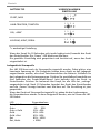
SETT ING TH E CHAR GER
Charge voltages
The LBC 500 has different charging voltages because each battery type needs
other voltages to ensure the longest duration of life. Therefore, the right charging
voltages need to be set beforehand by means of the ‘power/mode’ button.
The battery may be connected, but is not required.
Connect the charger to the mains. Push directly afterwards, within 5 seconds, on
the ‘power/mode’ button. The charger now is in its setup mode. By way of
pressing the button you can choose between the ‘setting’ LED’s. Each different
LED stands for a charge voltage setting. For the voltages, see page 36.
The schedule below is a directive. Always check if the recommended charging
voltages match with the charging guides of your battery. Most of all AGM
batteries have a large diversity of charge voltages, so for this type of battery it is
even more important that the advised charge voltages are verified.
Never set the charger to your own opinion. This can lead to irreparable damage to
the battery.
Important
The charger can only run the set-up mode after connection with the mains. So
when the charger for instance is reactivated from its stand-by mode, it can’t be
set.
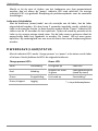
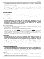
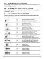
BATTERY TYPE
SUGGESTED SETTING
START, WET
SEMI-TRACTION, TRACTION
GEL, AGM¹
CALCIUM, AGM², SPIRAL
*= factory setting
The charger will leave the setup-mode if the button isn’t used for 10 seconds. In
this case the ‘ power’ LED will flash two times. The chosen setting will remain in
the memory of the charger and the setting LED lights when the charger is on.
1 2 3 4
1 2 3 4
1 2 3 4
1 2 3 4
*

17
English
Charger as power supply
The LBC 500 has a special setting for the use as a power supply. In this case the
charger will give one, constant voltage. The users can be connected to the
charger directly, so without intervention of a battery.
Connect the charger to the mains voltage. Directly afterwards, within 5 seconds,
press the ‘power/mode’ button. The charger now is in its set-up mode. Push the
button repeatedly until all LED from ‘settings’ are out.
If the charger is in its power supply function, the three charge status LED’s are
used to indicate the height of the load. This way you know how much power the
charger supplies.
LED Current
Green, flashes 0%
Green 1% - 20%
Green + yellow 21% - 40%
Yellow 41% - 60%
Yellow + red 61% - 80%
Red 81% - 100%
Red, flashes > 100%
INST AL LATI O N
The atmosphere
The battery should be charged in an area with adequate ventilation because it
may emit explosive gases. Be sure that there is enough space around the charger.
This is important for the air circulation, for cooling of the charger and release of
gases emitted.
The LBC 500 may not be used outdoors.
Important
Don’t not charge when there is a fuel leak or fuel is evaporating.
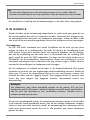
Mounting
The charger can be mounted in different ways with the mounting plate on the
bottem of the charger. Place the charger on a stabile underground.
With the optional mounting clamp PC1 the
charger can be easy placed en taken,
without removing the screws each time.

18
English
Connection
Due to the automatic voltage compensation we strongly recommend to leave the
cable length as it is. However, if you want to shorten the cable, it is important
that the length doesn’t become less than 0,7 meter. The cable length can be
extended, but that will also have effect on the automatic voltage compensation,
see chapter ‘FEATURES, section ‘automatic voltage compensation’.
Make sure that the mains voltage isn’t present.
Connect the red wire on the + connection of the battery by means of the battery
clamp. Repeat this with the black wire on the – connection of the battery.
For a fixed connection we advice to replace the battery clamps for the delivered
terminal rings. Cut off the wire as close as possible to the clamps.
Important
The battery junction that isn’t linked with the frame should be
connected firstly. The other junction must be made with the frame.
when the charger is to be used in an aluminium or steel ship/vessel,
it must be insulated by suspension. That is, in order to avoid
electrolysis, the casing of the charger may not be in contact with the
ship.
The connection between the charger and the battery must be made
some distance from the fuel installation.
Advice
It is advisable to mount a fuse between the + pole of the battery and the + bolt
of the charger. Always use a fuse that is heavier than the charge current.
After installing the charger and setting the charge voltages, the charger is ready
for use.
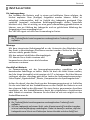
IN U S E
When the charger will be connected to the mains and the set-up mode isn’t used,
the charger will flash two times after 5 seconds and, if the battery is connected,
the charge process will start. When the mains is already present and the battery
will be connected, the charge process will also start automatically.
The charge process
The LBC 500 standards has a 4-stage process to charge en maintain the battery
the correct way. The charger will always start in the first stage, the bulk phase
(LED red). This first stage has a minimum time length of 30 minutes, so also when
a full battery is connected. In the second stage, the equalize stage (LED yellow)
the will be charged to 100%. The length of the charging time depends on the
battery quality, battery capacity, depth of discharge and the current draw of any
present users. Furthermore any faults could delay the process.

19
English
If the charge process is finished, the charger will switch automatically to the float
charge (LED green) keeping the battery under continues maintenance. If the
charger is in this stage for 24 hours at a minor current, the charger will go to its
‘jogging’ mode. This is a special charge stage for batteries that aren’t used for a
longer period of time, for instance during a winter break.
Important
The charging process may only be stopped when it is finished, so when the
green LED from the charging process lights or flashes. If the charging process
is interrupted before it is completed, the battery loses its charge and its acid
balance.
When disconnecting the battery, at interruption of the mains voltage or when the
charger is put in its stand-by function, the current charge process will stop. When
a battery is re-connected, the mains voltage is present again or when the charger
is re-activated from its stand-by function, in all cases a new charge process will
start.
When a problem is detected at the start of during the charge process, the ‘power’
LED will light up red. All other LED’s are out. Advice the Trouble Shooter for the
needed actions.
Turning the charger on/off
With the push button ‘power/mode’ button on the front side, the charger can be
turned off. Push and hold this button for 2 seconds, the charger will turn in its
stand-by function. In this stand-by mode the “Power” LED will flash two times
every 10 seconds. During this period the charger is in its power save mode.
To re-activate the charger, the ‘power/mode’ button must be pushed shortly. The
‘power’ LED will turn to green again. If a battery is present, a new charge process
will start directly.
OVER V IE W
(
CHAR GE
)
ST ATU S
With the ‘charging process’ LED’s and the ‘ power’ LED the status of the battery
charger can be followed.
Charge process:
Power:
Red Bulk stage Green Charger activated
Yellow Equalize stage
Flashes two times
every 10 seconds
Charger de
-
activated
(s
tandby
mode
)
Green Float stage Red Problem detected*
Green, flashes Jogging
*= advise the trouble shooter

20
English
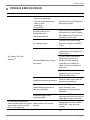
TROUBL E
SHO OTING
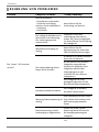
Problem (Possible) cause Action
Power LED lights red
*
.
Battery connection problem:
- No battery present
- Bad connection between
battery and charger
- Reverse polarity
- Short circuit
Check the connection to the
battery on faults.
Charger is in a thermical stop.
The charging process will
continue automatically when
the charger has cooled down.
AC input too low.
Check the mains voltage. It
should be higher than 180VAC.
The bulk stage takes longer
than 14 hours.
The battery is damaged/
broken. Check the battery.
Heavy users present during
charge process. Shut down as
many users as possible.
The charger has insufficient
current for the concerning
battery capacity.
Hardware/software problem.
Send the charger back to
supplier/manufacturer.
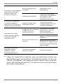
Warning for a too low battery
voltage.
Indication will light for 3 min.
The charge process will start as
usual.
Battery voltage too high.
Charge process stopped.
Check if the system voltage is
the same as the output voltage
of the charger
The battery is connected to
the charger and the charger
does not work. No LED’s burn.
No input voltage present. Check the mains voltage.
Input fuse broken.
Replace the fuse or return the
charger to the retailer/
manufacturer
>>>
Seite wird geladen ...
Seite wird geladen ...
Seite wird geladen ...
Seite wird geladen ...
Seite wird geladen ...
Seite wird geladen ...
Seite wird geladen ...
Seite wird geladen ...
Seite wird geladen ...
Seite wird geladen ...
Seite wird geladen ...
Seite wird geladen ...
Seite wird geladen ...
Seite wird geladen ...
Seite wird geladen ...
Seite wird geladen ...
Seite wird geladen ...
Seite wird geladen ...
-
 1
1
-
 2
2
-
 3
3
-
 4
4
-
 5
5
-
 6
6
-
 7
7
-
 8
8
-
 9
9
-
 10
10
-
 11
11
-
 12
12
-
 13
13
-
 14
14
-
 15
15
-
 16
16
-
 17
17
-
 18
18
-
 19
19
-
 20
20
-
 21
21
-
 22
22
-
 23
23
-
 24
24
-
 25
25
-
 26
26
-
 27
27
-
 28
28
-
 29
29
-
 30
30
-
 31
31
-
 32
32
-
 33
33
-
 34
34
-
 35
35
-
 36
36
-
 37
37
-
 38
38


Proosten Electronics Profline LBC 500 Benutzerhandbuch
- Typ
- Benutzerhandbuch
in anderen Sprachen
Andere Dokumente
-
VOLTCRAFT BC-10 Operating Instructions Manual
-
-
Victron energy BMS 12/200 Bedienungsanleitung
-
-
-
-
-
protech MEGA PEAK 3000 Benutzerhandbuch
-
-
Victron energy Blue Power 12/5 Benutzerhandbuch