MSI G52-75221XI Bedienungsanleitung
- Kategorie
- Motherboards
- Typ
- Bedienungsanleitung
Dieses Handbuch eignet sich auch für

X58A-GD45 series
MS-7522 (v5.x) Mainboard
G52-75221XI
Seite wird geladen ...
Seite wird geladen ...
Seite wird geladen ...

Preface
MS-7522
Preface
v
Preface
MS-7522
Preface
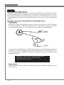
WEEE (Waste Electrical and Electronic Equipment) Statement
ENGLISH
To protect the global environment and as an environmentalist, MSI must
remind you that...
Under the European Union (“EU”) Directive on Waste Electrical and Elec-
tronic Equipment, Directive 2002/96/EC, which takes eect on August 13,
2005, products of “electrical and electronic equipment” cannot be discarded
as municipal waste anymore and manufacturers of covered electronic equip-
ment will be obligated to take back such products at the end of their useful life. MSI will
comply with the product take back requirements at the end of life of MSI-branded prod-
ucts that are sold into the EU. You can return these products to local collection points.
DEUTSCH
Hinweis von MSI zur Erhaltung und Schutz unserer Umwelt
Gemäß der Richtlinie 2002/96/EG über Elektro- und Elektronik-Altgeräte dürfen Elek-
tro- und Elektronik-Altgeräte nicht mehr als kommunale Abfälle entsorgt werden. MSI
hat europaweit verschiedene Sammel- und Recyclingunternehmen beauftragt, die in
die Europäische Union in Verkehr gebrachten Produkte, am Ende seines Lebenszyklus
zurückzunehmen. Bitte entsorgen Sie dieses Produkt zum gegebenen Zeitpunkt aus-
schliesslich an einer lokalen Altgerätesammelstelle in Ihrer Nähe.
FRANÇAIS
En tant qu’écologiste et an de protéger l’environnement, MSI tient à rappeler ceci...
Au sujet de la directive européenne (EU) relative aux déchets des équipement élec-
triques et électroniques, directive 2002/96/EC, prenant eet le 13 août 2005, que les
produits électriques et électroniques ne peuvent être déposés dans les décharges ou
tout simplement mis à la poubelle. Les fabricants de ces équipements seront obligés de
récupérer certains produits en n de vie. MSI prendra en compte cette exigence relative
au retour des produits en n de vie au sein de la communauté européenne. Par con-
séquent vous pouvez retourner localement ces matériels dans les points de collecte.
РУССКИЙ
Компания MSI предпринимает активные действия по защите окружающей среды,
поэтому напоминаем вам, что....
В соответствии с директивой Европейского Союза (ЕС) по предотвращению
загрязнения окружающей среды использованным электрическим и электронным
оборудованием (директива WEEE 2002/96/EC), вступающей в силу 13
августа 2005 года, изделия, относящиеся к электрическому и электронному
оборудованию, не могут рассматриваться как бытовой мусор, поэтому
производители вышеперечисленного электронного оборудования обязаны
принимать его для переработки по окончании срока службы. MSI обязуется
соблюдать требования по приему продукции, проданной под маркой MSI на
территории EC, в переработку по окончании срока службы. Вы можете вернуть
эти изделия в специализированные пункты приема.

vi
Preface
MS-7522
Preface
Preface
MS-7522
Preface
ESPAÑOL
MSI como empresa comprometida con la protección del medio ambiente, recomienda:
Bajo la directiva 2002/96/EC de la Unión Europea en materia de desechos y/o equi-
pos electrónicos, con fecha de rigor desde el 13 de agosto de 2005, los productos
clasicados como “eléctricos y equipos electrónicos” no pueden ser depositados en
los contenedores habituales de su municipio, los fabricantes de equipos electrónicos,
están obligados a hacerse cargo de dichos productos al termino de su período de vida.
MSI estará comprometido con los términos de recogida de sus productos vendidos en
la Unión Europea al nal de su periodo de vida. Usted debe depositar estos productos
en el punto limpio establecido por el ayuntamiento de su localidad o entregar a una
empresa autorizada para la recogida de estos residuos.
NEDERLANDS
Om het milieu te beschermen, wil MSI u eraan herinneren dat….
De richtlijn van de Europese Unie (EU) met betrekking tot Vervuiling van Electrische
en Electronische producten (2002/96/EC), die op 13 Augustus 2005 in zal gaan kun-
nen niet meer beschouwd worden als vervuiling. Fabrikanten van dit soort producten
worden verplicht om producten retour te nemen aan het eind van hun levenscyclus.
MSI zal overeenkomstig de richtlijn handelen voor de producten die de merknaam MSI
dragen en verkocht zijn in de EU. Deze goederen kunnen geretourneerd worden op
lokale inzamelingspunten.
SRPSKI
Da bi zaštitili prirodnu sredinu, i kao preduzeće koje vodi računa o okolini i prirodnoj
sredini, MSI mora da vas podesti da…
Po Direktivi Evropske unije (“EU”) o odbačenoj ekektronskoj i električnoj opremi, Di-
rektiva 2002/96/EC, koja stupa na snagu od 13. Avgusta 2005, proizvodi koji spadaju
pod “elektronsku i električnu opremu” ne mogu više biti odbačeni kao običan otpad i
proizvođači ove opreme biće prinuđeni da uzmu natrag ove proizvode na kraju njihovog
uobičajenog veka trajanja. MSI će poštovati zahtev o preuzimanju ovakvih proizvoda
kojima je istekao vek trajanja, koji imaju MSI oznaku i koji su prodati u EU. Ove proiz-
vode možete vratiti na lokalnim mestima za prikupljanje.
POLSKI
Aby chronić nasze środowisko naturalne oraz jako rma dbająca o ekologię, MSI przy-
pomina, że...
Zgodnie z Dyrektywą Unii Europejskiej (“UE”) dotyczącą odpadów produktów elektry-
cznych i elektronicznych (Dyrektywa 2002/96/EC), która wchodzi w życie 13 sierpnia
2005, tzw. “produkty oraz wyposażenie elektryczne i elektroniczne “ nie mogą być trak-
towane jako śmieci komunalne, tak więc producenci tych produktów będą zobowiązani
do odbierania ich w momencie gdy produkt jest wycofywany z użycia. MSI wypełni
wymagania UE, przyjmując produkty (sprzedawane na terenie Unii Europejskiej) wy-
cofywane z użycia. Produkty MSI będzie można zwracać w wyznaczonych punktach
zbiorczych.

Preface
MS-7522
Preface
vii
Preface
MS-7522
Preface
TÜRKÇE
Çevreci özelliğiyle bilinen MSI dünyada çevreyi korumak için hatırlatır:
Avrupa Birliği (AB) Kararnamesi Elektrik ve Elektronik Malzeme Atığı, 2002/96/EC
Kararnamesi altında 13 Ağustos 2005 tarihinden itibaren geçerli olmak üzere, elektrikli
ve elektronik malzemeler diğer atıklar gibi çöpe atılamayacak ve bu elektonik cihazların
üreticileri, cihazların kullanım süreleri bittikten sonra ürünleri geri toplamakla yükümlü
olacaktır. Avrupa Birliği’ne satılan MSI markalı ürünlerin kullanım süreleri bittiğinde MSI
ürünlerin geri alınması isteği ile işbirliği içerisinde olacaktır. Ürünlerinizi yerel toplama
noktalarına bırakabilirsiniz.
ČESKY
Záleží nám na ochraně životního prostředí - společnost MSI upozorňuje...
Podle směrnice Evropské unie (“EU”) o likvidaci elektrických a elektronických výrobků
2002/96/EC platné od 13. srpna 2005 je zakázáno likvidovat “elektrické a elektronické
výrobky” v běžném komunálním odpadu a výrobci elektronických výrobků, na které se
tato směrnice vztahuje, budou povinni odebírat takové výrobky zpět po skončení je-
jich životnosti. Společnost MSI splní požadavky na odebírání výrobků značky MSI,
prodávaných v zemích EU, po skončení jejich životnosti. Tyto výrobky můžete odevzdat
v místních sběrnách.
MAGYAR
Annak érdekében, hogy környezetünket megvédjük, illetve környezetvédőként fellépve
az MSI emlékezteti Önt, hogy ...
Az Európai Unió („EU”) 2005. augusztus 13-án hatályba lépő, az elektromos és elek-
tronikus berendezések hulladékairól szóló 2002/96/EK irányelve szerint az elektromos
és elektronikus berendezések többé nem kezelhetőek lakossági hulladékként, és az
ilyen elektronikus berendezések gyártói kötelessé válnak az ilyen termékek visszavé-
telére azok hasznos élettartama végén. Az MSI betartja a termékvisszavétellel kapc-
solatos követelményeket az MSI márkanév alatt az EU-n belül értékesített termékek
esetében, azok élettartamának végén. Az ilyen termékeket a legközelebbi gyűjtőhelyre
viheti.
ITALIANO
Per proteggere l’ambiente, MSI, da sempre amica della natura, ti ricorda che….
In base alla Direttiva dell’Unione Europea (EU) sullo Smaltimento dei Materiali Elettrici
ed Elettronici, Direttiva 2002/96/EC in vigore dal 13 Agosto 2005, prodotti appartenenti
alla categoria dei Materiali Elettrici ed Elettronici non possono più essere eliminati come
riuti municipali: i produttori di detti materiali saranno obbligati a ritirare ogni prodotto
alla ne del suo ciclo di vita. MSI si adeguerà a tale Direttiva ritirando tutti i prodotti
marchiati MSI che sono stati venduti all’interno dell’Unione Europea alla ne del loro
ciclo di vita. È possibile portare i prodotti nel più vicino punto di raccolta

viii
Preface
MS-7522
Preface
Preface
MS-7522
Preface
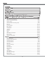
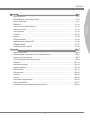
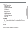
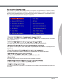
Contents
Copyright Notice ............................................................................................ ii
Trademarks .................................................................................................... ii
Revision History............................................................................................. ii
Technical Support.......................................................................................... ii
Safety Instructions .........................................................................................iii
FCC-B Radio Frequency Interference Statement.......................................... iv
WEEE (Waste Electrical and Electronic Equipment) Statement .................... v
English ...................................................................................................... En-1
Mainboard Specications ...................................................................................En-2
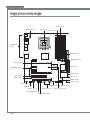
Quick Components Guide ..................................................................................En-4
Screw Holes .......................................................................................................En-5
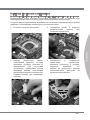
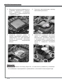
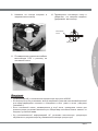
CPU (Central Processing Unit) ..........................................................................En-6
Memory ............................................................................................................En-10
Power Supply ...................................................................................................En-13
Back Panel .......................................................................................................En-14
Connectors .......................................................................................................En-16
Jumpers ...........................................................................................................En-22
Buttons .............................................................................................................En-23
Slots .................................................................................................................En-24
LED Status Indicators ......................................................................................En-25
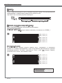
BIOS Setup ......................................................................................................En-27
Software Information ........................................................................................En-39
Deutsch .................................................................................................... De-1
Spezikationen .................................................................................................. De-2
Komponenten-Übersicht ................................................................................... De-4
Schraubenlöcher ............................................................................................... De-5
CPU (Prozessor) ............................................................................................... De-6
Speicher .......................................................................................................... De-10
Stromversorgung ............................................................................................. De-13
Rücktafel ......................................................................................................... De-14
Anschlüssen .................................................................................................... De-16
Steckbrücke .................................................................................................... De-22
Tasten ............................................................................................................. De-23
Steckplätze ...................................................................................................... De-24
LED Statusanzeige ......................................................................................... De-25
BIOS Setup ..................................................................................................... De-27
Software-Information ....................................................................................... De-39
Seite wird geladen ...


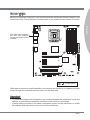
English
X58A-GD45
Series
Europe version
Seite wird geladen ...
Seite wird geladen ...

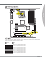
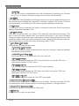
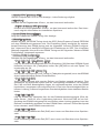
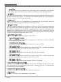
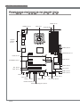
En-4
MS-7522 Mainboard
RE SET
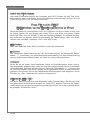
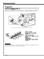
Quick Components Guide
Back Panel,
En-14
CPU, En-6
DDR3, En-10
JPWR3, En-13
CPUFAN, En-17
SYSFAN2/5, En-17
SYSFAN1/3, En-17
JPWR1, En-13
SATA, En-16
JUSB3, En-18
JCI1, En-21
JTPM1, En-20
SYSFAN4, En-17
JFP1, JFP2, En-20
JBAT1, En-22
JCOM1, En-17
JUSB1,2 En-18
Reset Button, En-23
Power Button, En-23
J1394_1, En-19
JCD1, En-17
JAUD1, En-21
JSP1, En-19
PCIE, En-24
PCI, En-24
Seite wird geladen ...
Seite wird geladen ...
Seite wird geladen ...
Seite wird geladen ...
Seite wird geladen ...

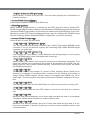
En-10
MS-7522 Mainboard
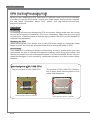
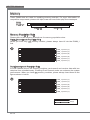
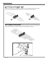
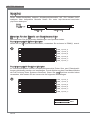
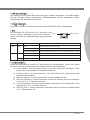
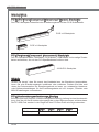
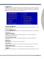
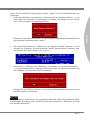
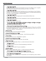
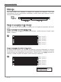
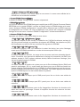
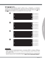
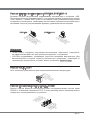
Memory
These DIMM slots are used for installing memory modules. For more information on
compatible components, please visit
http://www.msi.com/index.php?func=testreport
DDR3
240-pin, 1.5V
48x2=96 pin 72x2=144 pin
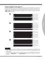
Memory Population Rule
Please refer to the following illustrations for memory population rules.
Single-Channel mode Population Rule
When you have only one memory module, please always insert it into the DIMM_1
rst.
1
DIMM_2 (Channel_A)
DIMM_1 (Channel_A)
DIMM_4 (Channel_B)
DIMM_3 (Channel_B)
DIMM_6 (Channel_C)
DIMM_5 (Channel_C)
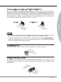
Dual-Channel mode Population Rule
In Dual-Channel mode, the memory modules can transmit and receive data with two
data bus lines simultaneously. Enabling Dual-Channel mode can enhance the system
performance. When you have two memory modules, please always insert them as the
gures shown in below.
2
DIMM_2 (Channel_A)
DIMM_1 (Channel_A)
DIMM_4 (Channel_B)
DIMM_3 (Channel_B)
DIMM_6 (Channel_C)
DIMM_5 (Channel_C)
Installed
Empty

En-11
English
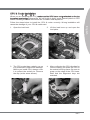
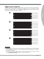
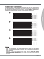
Triple-Channel mode Population Rule
In Triple-Channel mode, the memory modules can transmit and receive data with three
data bus lines simultaneously. Enabling Triple-Channel mode can enhance the best
system performance. When you have three or more memory modules, please always
insert them as the gures shown in below.
3
DIMM_2 (Channel_A)
DIMM_1 (Channel_A)
DIMM_4 (Channel_B)
DIMM_3 (Channel_B)
DIMM_6 (Channel_C)
DIMM_5 (Channel_C)
4
DIMM_2 (Channel_A)
DIMM_1 (Channel_A)
DIMM_4 (Channel_B)
DIMM_3 (Channel_B)
DIMM_6 (Channel_C)
DIMM_5 (Channel_C)
5
DIMM_2 (Channel_A)
DIMM_1 (Channel_A)
DIMM_4 (Channel_B)
DIMM_3 (Channel_B)
DIMM_6 (Channel_C)
DIMM_5 (Channel_C)
6
DIMM_2 (Channel_A)
DIMM_1 (Channel_A)
DIMM_4 (Channel_B)
DIMM_3 (Channel_B)
DIMM_6 (Channel_C)
DIMM_5 (Channel_C)
Important
DDR3 memory modules are not interchangeable with DDR2 and the DDR3 standard
is not backwards compatible. You should always install DDR3 memory modules in
the DDR3 DIMM slots.
In Triple-Channel/ Dual-Channel mode, make sure that you install memory modules
of the same type and density in dierent channel DIMM slots.
•
•
Seite wird geladen ...

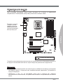
En-13
English
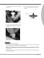
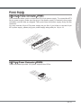
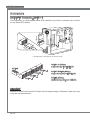
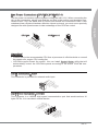
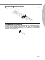
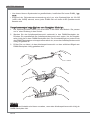
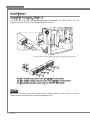
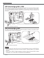
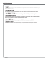
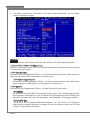
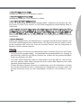
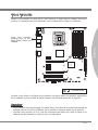
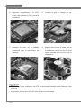
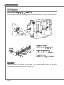
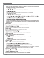
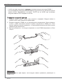
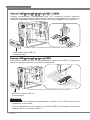
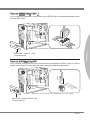
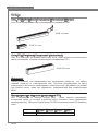
Power Supply
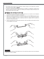
ATX 24-pin Power Connector: JPWR1
This connector allows you to connect an ATX 24-pin power supply. To connect the ATX
24-pin power supply, make sure the plug of the power supply is inserted in the proper
orientation and the pins are aligned. Then push down the power supply rmly into the
connector.
You may use the 20-pin ATX power supply as you like. If you’d like to use the 20-pin
ATX power supply, please plug your power supply along with pin 1 & pin 13.
13.+3.3
V
1.+3.3
V
14.-12V
2.+3.3
V
15.Ground
3
.Ground
16.PS-ON
#
4.+5
V
17.Ground
5
.Ground
18.Ground
6.+5
V
19.Ground
7
.Ground
22.+5
V
10.+12V
20.Res
8.PW
R O
K
23.+5
V
11
.+12V
21.+5
V
9.5VSB
24.Ground
12.+3.3
V
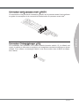
ATX 8-pin Power Connector: JPWR3
These connectors provide 12V power output to the CPUs.
7.+12V
3.Ground
5.+12V
1.
Ground
8.+12V
4
.Ground
6.+12V
2
.Ground
Seite wird geladen ...
Seite wird geladen ...

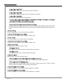
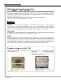
En-16
MS-7522 Mainboard
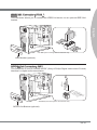
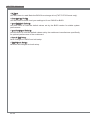
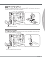
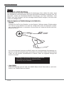
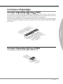
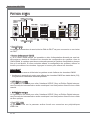
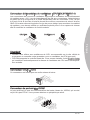
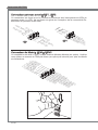
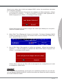
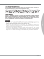
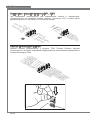
Connectors
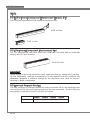
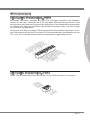
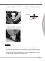
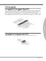
Serial ATA Connector: SATA1~9
This connector is a high-speed Serial ATA interface port. Each connector can connect
to one Serial ATA device.
* The MB layout in this gure is for reference only.
SATA5_6
SATA3_4
SATA1_2
SATA1~6 (3Gb/s)
supported by Intel
®
ICH10R
SATA7/ SATA8 (6Gb/s)
supported by Marvell
®
SE9128
SATA7_8
SATA9
SATA9 (3Gb/s)
supported by JMicron
®
JMB362
Important
Please do not fold the Serial ATA cable into 90-degree angle. Otherwise, data loss may
occur during transmission.

En-17
English
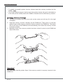
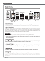
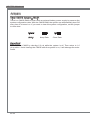
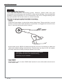
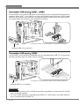
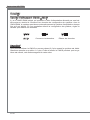
Fan Power Connectors: CPUFAN,SYSFAN1~5
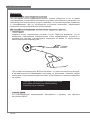
The fan power connectors support system cooling fan with +12V. When connecting the
wire to the connectors, always note that the red wire is the positive and should be con-
nected to the +12V; the black wire is Ground and should be connected to GND. If the
mainboard has a System Hardware Monitor chipset on-board, you must use a specially
designed fan with speed sensor to take advantage of the CPU fan control.
1
.
G
r
o
u
n
d
2
.
+
1
2
V
3
.
S
e
n
s
o
r
4
.
C
o
n
t
r
o
l
1
.
G
r
o
u
n
d
2
.
+
1
2
V
3
.
S
e
n
s
o
r
CPUFAN SYSFAN1~5
Important
Please refer to the recommended CPU fans at processor’s ocial website or consult
the vendors for proper CPU cooling fan.
CPUFAN support Smart fan control. You can install Control Center utility that will
automatically control the CPUFAN speeds according to the actual CPUFAN tem-
peratures.
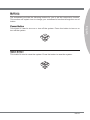
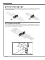
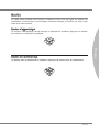
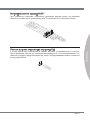
CD-In Connector: JCD1
This connector is provided for external audio input.
4
.
R
3
.
G
r
o
u
n
d
2
.
G
r
o
u
n
d
1
.
L
Serial Port Connector: JCOM1
This connector is a 16550A high speed communication port that sends/receives 16
bytes FIFOs. You can attach a serial device.
1
.
D
C
D
3
.
S
O
U
T
1
0
.
N
o
P
i
n
5
.
G
r
o
u
n
d
7
.
R
T
S
9
.
R
I
8
.
C
T
S
6
.
D
S
R
4
.
D
T
R
2
.
S
I
N
•
•
Seite wird geladen ...
Seite wird geladen ...

En-20
MS-7522 Mainboard
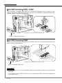
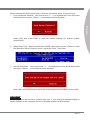
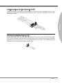
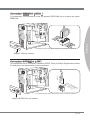
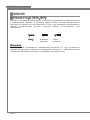
Front Panel Connectors: JFP1, JFP2
These connectors are for electrical connection to the front panel switches and LEDs.
The JFP1 is compliant with Intel
®
Front Panel I/O Connectivity Design Guide.
1
.Ground
3.Suspend
LE
D
5.Power
LE
D
7.No Pi
n
8.
+
6.
-
4.
+
2.
-
Buzzer
S
peaker
1.+
3.
-
10.No
Pi
n
5.
-
Reset
S
witch
HDD
LE
D
P
ower
S
witch
P
ower
LE
D
7.
+
9.Reserve
d
8.
-
6.
+
4.
-
2.
+
JFP1
JFP2
TPM Module connector: JTPM1
This connector connects to a TPM (Trusted Platform Module) module (optional). Please
refer to the TPM security platform manual for more details and usages.
1
0
.
N
o
P
i
n
1
4
.
G
r
o
u
n
d
8
.
5
V
P
o
w
e
r
1
2
.
G
r
o
u
n
d
6
.
S
e
r
i
a
l
I
R
Q
4
.
3
.
3
V
P
o
w
e
r
2
.
3
V
S
t
a
n
d
b
y
p
o
w
e
r
1
.
L
P
C
C
l
o
c
k
3
.
L
P
C
R
e
s
e
t
5
.
L
P
C
a
d
d
r
e
s
s
&
d
a
t
a
p
i
n
0
7
.
L
P
C
a
d
d
r
e
s
s
&
d
a
t
a
p
i
n
1
9
.
L
P
C
a
d
d
r
e
s
s
&
d
a
t
a
p
i
n
2
1
1
.
L
P
C
a
d
d
r
e
s
s
&
d
a
t
a
p
i
n
3
1
3
.
L
P
C
F
r
a
m
e
Seite wird geladen ...
Seite wird geladen ...
Seite wird geladen ...
Seite wird geladen ...
Seite wird geladen ...
Seite wird geladen ...
Seite wird geladen ...
Seite wird geladen ...
Seite wird geladen ...
Seite wird geladen ...
Seite wird geladen ...
Seite wird geladen ...
Seite wird geladen ...
Seite wird geladen ...
Seite wird geladen ...
Seite wird geladen ...

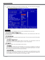
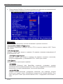
En-37
English
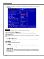
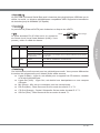
Auto Disable PCI/PCI-E Frequency
When set to [Enabled], the system will remove (turn o) clocks from empty PCI and
PCI-E slots to minimize the electromagnetic interference (EMI).
CPU Voltage (V)/ CPU PLL Voltage (V)/ QPI Voltage (V)/ DRAM Voltage (V)/ DDR_
VREF_CA_A (V)/ DDR_VREF_CA_B (V)/ DDR_VREF_CA_C (V)/ DDR_VREF_DQ_A
(V)/ DDR_VREF_DQ_B (V)/ DDR_VREF_DQ_C (V)/ IOH Voltage (V)/ ICH Voltage (V)
These items are used to adjust the voltage of CPU, Memory and chipset.
Spread Spectrum
When the mainboard’s clock generator pulses, the extreme values (spikes) of the pulses
create EMI (Electromagnetic Interference). The Spread Spectrum function reduces the
EMI generated by modulating the pulses so that the spikes of the pulses are reduced
to atter curves.
Important
If you do not have any EMI problem, leave the setting at [Disabled] for optimal system
stability and performance. But if you are plagued by EMI, select the value of Spread
Spectrum for EMI reduction.
The greater the Spread Spectrum value is, the greater the EMI is reduced, and the
system will become less stable. For the most suitable Spread Spectrum value, please
consult your local EMI regulation.
Remember to disable Spread Spectrum if you are overclocking because even a slight
jitter can introduce a temporary boost in clock speed which may just cause your over-
clocked processor to lock up.
▶
▶
▶
•
•
•
Seite wird geladen ...
Seite wird geladen ...


Deutsch
X58A-GD45
Serie
Europe Version

De-2
MS-7522 Mainboard
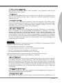
Spezikationen
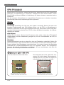
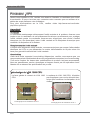
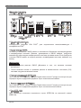
Prozessoren
Intel
®
i7 Prozessor für Sockel LGA1366
(Weitere CPU Informationen nden Sie unter http://www.msi.com/index.
php?func=cpuform2)
QPI
Bis zu 6,4 GT/s
Chipsatz
North-Bridge : Intel
®
X58 Chipsatz
South-Bridge : Intel
®
ICH10R Chipsatz
Speicher
6 DDR3 DIMMs unterstützen DDR3 2133*(OC)/ 1800*(OC) /1600*(OC)/ 1333/ 1066
/ 800 DRAM (max. 24GB)
Unterstützt die Modi Dual-Kanal/ Drei-Kanal
*(Weitere Informationen zu kompatiblen Speichermodulen nden Sie unter
http://www.msi.com/index.php?func=testreport)
LAN
Unterstützt LAN 10/100/1000 Fast Ethernet über Realtek
®
RTL8111E
IEEE 1394
2 IEEE 1394 Anschlüsse über VIA
®
VT6308 (1x Stiftleiste, 1x Rückwand)
Audio
Onboard Soundchip Realtek
®
ALC892 (True Blu-ray Audio)
8-Kanal Audio-Ausgang mit „Jack Sensing“
Erfüllt die Azalia Spezikationen
SATA
7 SATA 3Gb/s Anschlüsse (SATA1~6) über Intel
®
ICH10R und (SATA9) über JMicron
®
JMB362
2 SATA 6Gb/s Anschlüsse (SATA7~8) über Marvell
®
SE9128
1 eSATA Anschluss (Rückplatte) über JMicron
®
JMB362
USB 3.0
2 USB 3.0 Anschlüsse über NEC
®
uPD720200F1
RAID
SATA1~6 unterstützen die Intel
®
Matrix Storage Technologie (AHCI/ RAID 0/1/5/10)
über Intel
®
ICH10R
SATA7~8 Anschlüsse unterstützen die Modi RAID 0/ 1 über Marvell
®
SE9128
■
■
■
■
■
■
■
■
■
■
■
■
■
■
■
■
■

De-3
Deutsch
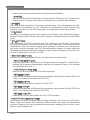
Anschlüsse
Hintere Ein-/ und Ausgänge
1 PS/2 Tastaturanschluss
1 PS/2 Mausanschluss
1 CMOS leeren-Taste
1 optischer S/PDIF-Ausgang
1 koaxialer S/PDIF-Ausgang
1 1394 Anschluss
8 USB 2.0 Anschlüsse
1 eSATA Anschluss
1 LAN Anschluss
6 Audiobuchsen
On-Board
2 USB 2.0 Stiftleisten
1 USB 3.0 Stiftleiste
1 1394 Stiftleiste
1 Gehäusekontaktschalter
1 TPM Stiftleiste
1 Serielle Stiftleiste
1 CD Stiftleiste für Audio Eingang
1 S/PDIF-Ausgang Stiftleiste
1 Audio Stiftleiste für Gehäuse Audio Ein-/ Ausgänge
1 Reset-Taste
1 Ein-/ Ausschalter
Steckplätze
2 PCIE 2.0 x16-Steckplätze (PCI_E2, PCI_E5)
1 PCIE 1.0 x16-Steckplatz (PCI_E6), unterstützt die Geschwindigkeit bis zu x4 PCIE
Wenn Sie die Erweiterungskarten in PCIEx1 Steckplätze (PCI_E1, PCI_E3 oder
PCI_E4) setzen möchten, werden diese PCI_E6 Lanes automatisch von x4 zu x1.
3 PCIE 2.0 x1-Steckplätze
1 PCI-Steckplatz
Form Faktor
ATX (24,4cm X 30,5 cm)
Montage
9 Montagebohrungen
* Wenn Sie für Bestellungen von Zubehör Teilenummern benötigen, nden Sie diese
auf unserer Produktseite unter http://www.msi.com/index.php
■
-
-
-
-
-
-
-
-
-
-
■
-
-
-
-
-
-
-
-
-
-
-
■
■
-
■
■
■
■

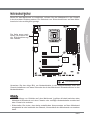
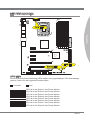
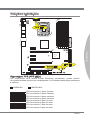
De-4
MS-7522 Mainboard
RE SET
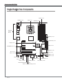
Komponenten-Übersicht
Rücktafel,
De-14
CPU, De-6
DDR3, De-10
JPWR3, De-13
CPUFAN, De-17
SYSFAN2/5, De-17
SYSFAN1/3, De-17
JPWR1, De-13
SATA, De-16
JUSB3, De-18
JCI1, De-21
JTPM1, De-20
SYSFAN4, De-17
JFP1, JFP2, De-20
JBAT1, De-22
JCOM1, De-17
JUSB1,2 De-18
Reset-Taste, De-23
Ein-/ Ausschalter, De-23
J1394_1, De-19
JCD1, De-17
JAUD1, De-21
JSP1, De-19
PCIE, De-24
PCI, De-24
Seite wird geladen ...
Seite wird geladen ...
Seite wird geladen ...
Seite wird geladen ...
Seite wird geladen ...
Seite wird geladen ...
Seite wird geladen ...
Seite wird geladen ...
Seite wird geladen ...
Seite wird geladen ...
Seite wird geladen ...
Seite wird geladen ...
Seite wird geladen ...
Seite wird geladen ...
Seite wird geladen ...
Seite wird geladen ...
Seite wird geladen ...
Seite wird geladen ...
Seite wird geladen ...
Seite wird geladen ...
Seite wird geladen ...
Seite wird geladen ...
Seite wird geladen ...
Seite wird geladen ...
Seite wird geladen ...
Seite wird geladen ...
Seite wird geladen ...
Seite wird geladen ...
Seite wird geladen ...
Seite wird geladen ...
Seite wird geladen ...
Seite wird geladen ...
Seite wird geladen ...
Seite wird geladen ...
Seite wird geladen ...
Seite wird geladen ...
Seite wird geladen ...
Seite wird geladen ...
Seite wird geladen ...
Seite wird geladen ...
Seite wird geladen ...
Seite wird geladen ...
Seite wird geladen ...
Seite wird geladen ...
Seite wird geladen ...
Seite wird geladen ...
Seite wird geladen ...
Seite wird geladen ...
Seite wird geladen ...
Seite wird geladen ...
Seite wird geladen ...
Seite wird geladen ...
Seite wird geladen ...
Seite wird geladen ...
Seite wird geladen ...
Seite wird geladen ...
Seite wird geladen ...
Seite wird geladen ...
Seite wird geladen ...
Seite wird geladen ...
Seite wird geladen ...
Seite wird geladen ...
Seite wird geladen ...
Seite wird geladen ...
Seite wird geladen ...
Seite wird geladen ...
Seite wird geladen ...
Seite wird geladen ...
Seite wird geladen ...
Seite wird geladen ...
Seite wird geladen ...
Seite wird geladen ...
Seite wird geladen ...
Seite wird geladen ...
Seite wird geladen ...
Seite wird geladen ...
Seite wird geladen ...
Seite wird geladen ...
Seite wird geladen ...
Seite wird geladen ...
Seite wird geladen ...
Seite wird geladen ...
Seite wird geladen ...
Seite wird geladen ...
Seite wird geladen ...
Seite wird geladen ...
Seite wird geladen ...
Seite wird geladen ...
Seite wird geladen ...
Seite wird geladen ...
Seite wird geladen ...
Seite wird geladen ...
Seite wird geladen ...
Seite wird geladen ...
Seite wird geladen ...
Seite wird geladen ...
Seite wird geladen ...
Seite wird geladen ...
Seite wird geladen ...
Seite wird geladen ...
Seite wird geladen ...
Seite wird geladen ...
Seite wird geladen ...
Seite wird geladen ...
Seite wird geladen ...
Seite wird geladen ...
Seite wird geladen ...
Seite wird geladen ...
Seite wird geladen ...
Seite wird geladen ...
Seite wird geladen ...
Seite wird geladen ...
Seite wird geladen ...
Seite wird geladen ...
Seite wird geladen ...
Seite wird geladen ...
-
 1
1
-
 2
2
-
 3
3
-
 4
4
-
 5
5
-
 6
6
-
 7
7
-
 8
8
-
 9
9
-
 10
10
-
 11
11
-
 12
12
-
 13
13
-
 14
14
-
 15
15
-
 16
16
-
 17
17
-
 18
18
-
 19
19
-
 20
20
-
 21
21
-
 22
22
-
 23
23
-
 24
24
-
 25
25
-
 26
26
-
 27
27
-
 28
28
-
 29
29
-
 30
30
-
 31
31
-
 32
32
-
 33
33
-
 34
34
-
 35
35
-
 36
36
-
 37
37
-
 38
38
-
 39
39
-
 40
40
-
 41
41
-
 42
42
-
 43
43
-
 44
44
-
 45
45
-
 46
46
-
 47
47
-
 48
48
-
 49
49
-
 50
50
-
 51
51
-
 52
52
-
 53
53
-
 54
54
-
 55
55
-
 56
56
-
 57
57
-
 58
58
-
 59
59
-
 60
60
-
 61
61
-
 62
62
-
 63
63
-
 64
64
-
 65
65
-
 66
66
-
 67
67
-
 68
68
-
 69
69
-
 70
70
-
 71
71
-
 72
72
-
 73
73
-
 74
74
-
 75
75
-
 76
76
-
 77
77
-
 78
78
-
 79
79
-
 80
80
-
 81
81
-
 82
82
-
 83
83
-
 84
84
-
 85
85
-
 86
86
-
 87
87
-
 88
88
-
 89
89
-
 90
90
-
 91
91
-
 92
92
-
 93
93
-
 94
94
-
 95
95
-
 96
96
-
 97
97
-
 98
98
-
 99
99
-
 100
100
-
 101
101
-
 102
102
-
 103
103
-
 104
104
-
 105
105
-
 106
106
-
 107
107
-
 108
108
-
 109
109
-
 110
110
-
 111
111
-
 112
112
-
 113
113
-
 114
114
-
 115
115
-
 116
116
-
 117
117
-
 118
118
-
 119
119
-
 120
120
-
 121
121
-
 122
122
-
 123
123
-
 124
124
-
 125
125
-
 126
126
-
 127
127
-
 128
128
-
 129
129
-
 130
130
-
 131
131
-
 132
132
-
 133
133
-
 134
134
-
 135
135
-
 136
136
-
 137
137
-
 138
138
-
 139
139
-
 140
140
-
 141
141
-
 142
142
-
 143
143
-
 144
144
-
 145
145
-
 146
146
-
 147
147
-
 148
148
-
 149
149
-
 150
150
-
 151
151
-
 152
152
-
 153
153
-
 154
154
-
 155
155
-
 156
156
-
 157
157
-
 158
158
-
 159
159
-
 160
160
-
 161
161
-
 162
162
-
 163
163
-
 164
164
-
 165
165
-
 166
166
-
 167
167
-
 168
168
-
 169
169
-
 170
170


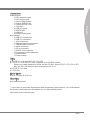
MSI G52-75221XI Bedienungsanleitung
- Kategorie
- Motherboards
- Typ
- Bedienungsanleitung
- Dieses Handbuch eignet sich auch für
in anderen Sprachen
- English: MSI G52-75221XI Owner's manual
- français: MSI G52-75221XI Le manuel du propriétaire
- русский: MSI G52-75221XI Инструкция по применению
Verwandte Artikel
-
MSI XPOWER Bedienungsanleitung
-
-
-
MSI 990FXA-GD80 Bedienungsanleitung
-
-
MSI G52-76601X7 Bedienungsanleitung
-
-
MSI Z68A-GD80 (B3) Benutzerhandbuch
-
-
MSI P67A-GD65 Bedienungsanleitung