
SMOKE ALARM PEBBLE LINK
USER MANUAL
SA703 Ver: 220617

Consumer contact:
GPBM Nordic AB
Argongatan 2 B
SE-431 53 Mölndal, Sweden
info@housegard.com

GBSNDKEST FIND
ENGLISH 4–24
SVENSKA 25–45
NORSK 46–66
DANSK 67–87
SUOMI 88–108
EESTI KEEL 109–129
DEUTSCH 109–129

4
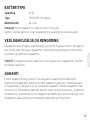
Congratulations on the purchase of your new smoke alarm device. We
recommend that you spend some time reading this instruction manual in order
to fully understand all the operational features. You will also find some hints and
advice to help you resolve any issues. Read all the safety instructions carefully
before use and keep for future reference.
The Housegard smoke alarm is designed to detect smoke particles, to reduce the
number of false alarms and to give an early warning if a fire occurs. Its operation
depends on correct positioning and maintenance.
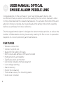
FEATURES
• Wireless connection
• Connect up to 12 pcs
• Sealed for life battery 10 years
• Both screws and adhesive 3M tape included
• High sensitivity and stability
• Test/Pause and Learn button
• LED diode indicates normal operation
• Low voltage warning
• Alarm memory
• End of life indication
• Twist aid accessory for mounting plate
• Dust cover included
GB USER MANUAL OPTICAL
SMOKE ALARM PEBBLE LINK

5
GBSNDKEST FIND
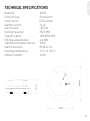
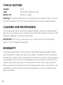
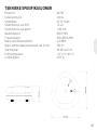
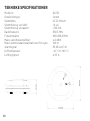
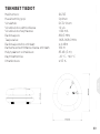
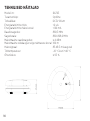
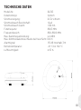
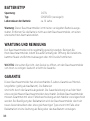
TECHNICAL SPECIFICATIONS
Model No: SA703
Detection type: Photoelectric
Power source: DC3V lithium
Standby current: <2 uA
Alarm current: <120 mA
Working frequency: 868,3 MHz
Frequency band: 868-868,6 MHz
Eective radiated power: ≤ 4 dBm
Transmission distance open air: 100 m
Alarm sound level: 85 dB at 3 m
Operating temperature: -10 °C to +40 °C
Ambient humidity: ≤ 95%

6
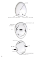
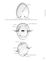
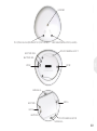
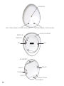
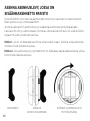
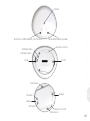
SLOT SLOT
POSITIONING COLUMN
BATTERY PIN +
BATTERY PIN –
SCREW HOLE
SCREW HOLE
BATTERY +
BATTERY – HOOK
HOOK
POSITIONING GROOVE
TEST/HUSH BUTTON /INDICATOR LEARN BUTTON / INDICATOR
BUZZER

7
GBSNDKEST FIND
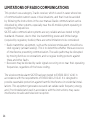
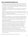
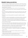
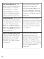
IMPORTANT SAFETY INFORMATION
• The smoke alarm device is battery-powered. It will not work without battery, or if
the battery is dead, removed or not correctly connected. Use only the specified
type of battery. DO NOT connect the smoke alarm device to any type of detector
or equipment other than what is stated in this manual.
• The test button provides a full test of all the smoke alarm’s functions. No other test
methods are required. Test smoke alarm devices every week to check that they are
working properly.
• Do not remove or disconnect the battery to stop false alarms, as this will cause the
smoke alarm to lose important functionality. Open a window or ventilate the air
around the smoke alarm device to stop the alarm and/or press the pause button.
• The smoke alarm device must be installed in line with all local and national rules
and regulations on installation.
• The smoke alarm device is intended for use in houses. In apartment blocks, each
apartment should be fitted with its own smoke alarm device. This smoke alarm
device is not suitable for use in non-residential buildings. The smoke alarm device is
not a replacement for a complete alarm system as required under law or by the fire
safety authorities.
• There may be reasons why a person in a household might not hear the alarm (e.g.
noise, deep sleep, impaired hearing). If you suspect that a person in the household
will not react to the smoke alarm device, specialist alarms should be installed.
• The smoke alarm device detects combustion particles (smoke) in the air. It does not
react to flames or gas. The smoke alarm device is designed to give o an audible
alarm if a fire is developing.
• No smoke alarm devices are entirely reliable and they cannot give a 100%
guarantee to protect life and property against fire. The smoke alarm device is no
replacement for insurance. Homeowners and tenants should take out life and home
insurance.
The smoke alarm device should be tested regularly and replaced

8
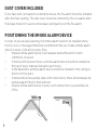
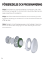
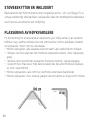
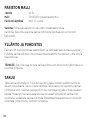
DUST COVER INCLUDED
If you have built, renovated or extended a house, the fire alarm should be installed
after the final cleaning. The dust cover should be removed by the occupants after
they have moved in to avoid unnecessary dust/particles in the fire alarm.
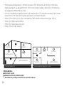
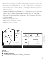
POSITIONING THE SMOKE ALARM DEVICE
In order to give an early warning, the smoke alarm needs to be installed where
the fire occurs. Housegard therefore recommends that you install a smoke alarm
device in every room and on every floor.
• Install a smoke alarm device in all separate bedrooms and in rooms
commonly occupied.
• In homes with several storeys, a smoke alarm device should be installed at
the top of every staircase between each storey.
• In the basement, a smoke alarm device should be installed in the ceiling at
the foot of the stairs.
• In bedrooms where people sleep with closed doors, there should always be
a smoke alarm fitted in the bedroom.
• Install a smoke alarm device in every room where there is a potential risk
of fire.

9
GBSNDKEST FIND
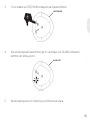
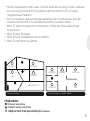
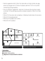
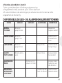
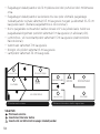
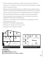
• If you install the smoke alarm in a passageway whose width is less than 3 m,
install it in the middle and install one unit every 12 m.
• Install the smoke alarm device in the middle of the ceiling. If you can’t,
install it at least 0,5 m from the wall (wall mounting not recommended).
• If you install the smoke alarm on sloped or peaked ceiling, the installation
position shall be at least 1 m from the highest point (see image below).
• At least 1,5 m from fluorescent lamp or neon lamp. (In case of electronic
interference).
• At least 3 m from the bathroom.
• At least 6 m from the kitchen or stove.
• At least 30 cm from the lamps.
KEY:
Minimal protection
Recommended/more substantial protection
∆ Smoke alarm devices with a pause function are recommended

10
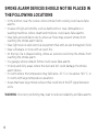
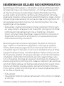
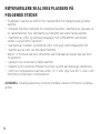
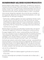
SMOKE ALARM DEVICES SHOULD NOT BE PLACED IN
THE FOLLOWING LOCATIONS
• In the kitchen, near the cooker, where smoke from cooking could cause false
alarms.
• In areas of high air humidity, such as bathrooms or near dishwashers or
washing machines, where steam and moisture could cause false alarms.
• Near fans and ventilation ducts, where air flows may prevent smoke from
reaching the smoke alarm device.
• Near light sources and electrical equipment that emit an electromagnetic field.
• Near a fireplace or stove with an open fire.
• At the top of a V-shaped ceiling, where air pockets could stop the smoke from
reaching the smoke alarm.
• In a garage, where exhaust fumes could cause false alarms.
• In dusty and dirty areas, where the dust and dirt could damage the smoke
alarm device.
• In rooms where the temperature may fall below -10 °C or rise above +40 °C, or
in rooms with large temperature variations.
• Areas that have large metal surfaces that could block the RF signal between
units.
WARNING: Incorrect positioning may lead to reduced reliability and false alarms.

11
GBSNDKEST FIND
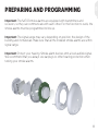
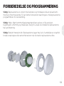
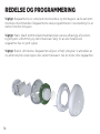
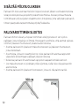
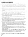
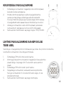
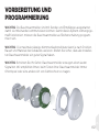
PREPARING AND PROGRAMMING
Important: The SA703 smoke alarms are equipped with transmitters and
receivers, so they can communicate with each other. For this function to work, the
smoke alarms must be programmed to link up.
Important: The signal range may vary depending on position, the design of the
building and its materials. Make sure that all the installed smoke alarms are within
signal range.
Important: Protect your hearing. Smoke alarm devices emit a loud audible signal.
We recommend that you always use earplugs or other hearing protection when
testing your smoke alarms.
GB

12
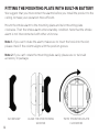
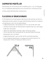
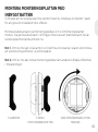
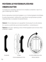
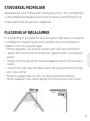
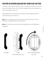
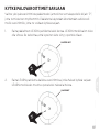
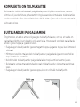
TWIST MOUNTING PLATE
CLOCKWISE
ALIGN THE POSITIONING
GROOVE
ACCESSORY
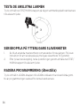
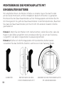
FITTING THE MOUNTING PLATE WITH BUILT-IN BATTERY
We suggest that you interconnect the alarms before you install the product to the
ceiling, to make your operation more ecient.
Mount the smoke alarm to the mounting plate and twist mounting plate
clockwise. Then the smoke alarm enters standby condition. Note that the smoke
alarm is not interconnected with other units now.
Note 1. If you can’t rotate the alarm, make sure to insert the hook into the slot,
please check if the column aligns with the position groove.
Note 2. If you can’t rotate the mounting plate easily, please use or twist aid
accessory in package.

13
GBSNDKEST FIND
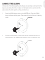
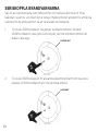
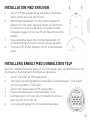
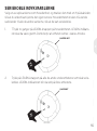
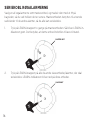
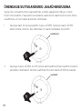
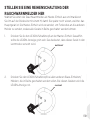
CONNECT THE ALARMS
Choose one of the smoke alarms as the Master unit and mark it with an M on the
back, so you know which one it is later on. The master unit is used to send the
radio code to the other alarms, so they all connect up.
1. Press the LEARN button twice on the MASTER unit. Then the LEARN
button indicator shall be green. That means this unit will be set in learning
mode.
2. Press the LEARN button of all the other SLAVE alarms that need to be
interconnected. The LEARN button indicator will be red on those units.
MASTER UNIT
X2
SLAVE UNIT
X1

14
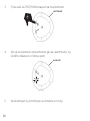
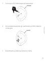
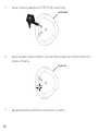
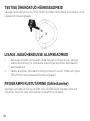
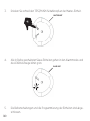
3. Press shortly the TEST button on the MASTER alarm.
4. All interconnected slave units will go into alarm mode and LEARN button
indicator will be flashing green.
5. Learning of interconnection is completed.
MASTER UNIT
X1
SLAVE UNIT

15
GBSNDKEST FIND
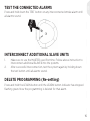
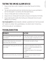
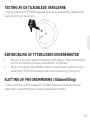
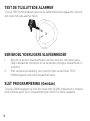
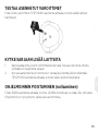
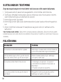
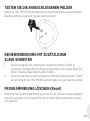
TEST THE CONNECTED ALARMS
Press and hold down the TEST button on any interconnected smoke alarm until
all alarms sound.
INTERCONNECT ADDITIONAL SLAVE UNITS
1. Make sure to use the MASTER used first time. Follow above instruction to
interconnect additional SLAVES into the systems.
2. After successful interconnection, test the system again by holding down
the test button until all alarms sound.
DELETE PROGRAMMING (Re-setting)
Press and hold the LEARN button until the LEARN button indicator has stopped
flashing green. Now the programming is deleted for that alarm.
HOLD

16
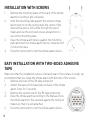
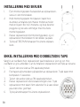
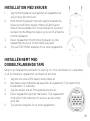
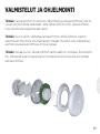
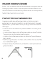
INSTALLATION WITH SCREWS
1. Remove the mounting plate on the back of the smoke
alarm by twisting it anti clockwise.
2. Hold the mounting plate against the selected instal-
lation position on the ceiling, mark the centre of the
holes with a pencil. Drill a hole through the pencil
marks and use the enclosed screws and anchors to
secure the mounting plate.
3. Place the smoke alarm device against the mounting
plate and twist the smoke alarm device clockwise until
it clicks into place.
4. Press the test button to test the smoke alarm device.
EASY INSTALLATION WITH TWO-SIDED ADHESIVE
TAPE
Make sure that the installation surface is flat and clean. If the surface is rough, we
recommend that you install the smoke alarm with the help of the screws.
1. Remove one side of the 3M tape protection
2. Attach the tape on the base plate on back of the smoke
alarm. Press for 5 seconds.
3. Remove the second side of the 3M tape protection.
4. Place the smoke alarm according to the manual. Press
the smoke alarm for five seconds against the ceiling to
make sure that it is well attached
5. Press the test button to test the smoke alarm device.

17
GBSNDKEST FIND
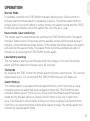
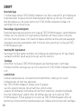
OPERATION
Normal Mode
In standby condition the TEST/HUSH indicator flashes every 344 seconds to
indicate that the smoke alarm is operating properly. The smoke alarm detects
smoke every 10 seconds. When it senses smoke, the alarm sounds and the TEST/
HUSH indicator flashes red at the same time, until the air is clear.
Pause mode (Low sensitivity)
The smoke alarm is desensitized by pushing the TEST/HUSH button. The alarm
indicator flashes every 10 seconds and no audible sound will be heard during 9
minutes, unless smoke becomes denser. If the smoke becomes denser, the alarm
will override the pause mode. The pause mode will end automatically after 9
minutes or by pressing the TEST/HUSH button again.
Low battery warning
The low battery warning will indicate when the voltage is too low, the smoke
alarm will then make short beeps every 43 seconds.
Test mode
By pressing the TEST button the smoke alarm will enter alarm mode. The unit will
make beeps every 0,5 second and the TEST/HUSH indicator will flash red.
Alarm Memory
This smoke alarm is equipped with an alarm memory, which provides a visual
indication when an alarm has been activated. When the TEST/HUSH button
indicator flashes green 3 times every 43 seconds, that means alarm has been
made during the last 24 hours. Please check if there is fire risk in detection
area. This indication will end after 24 hours or when pushing Test/Hush button.
First time you press test/mute button after alarm is made, the smoke alarm will
indicate by special alarm mode.

18
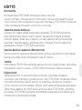
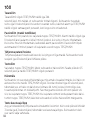
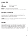
End of life mode
The time and working environment will cause the degeneration of smoke
chamber. When the product makes 3 short beeps every 43 seconds, it indicates
end-of-unit-life. You should replace the smoke alarm with a new one.
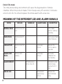
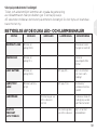
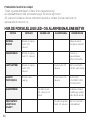
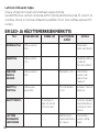
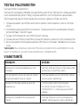
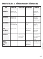
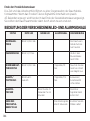
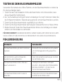
MEANING OF THE DIFFERENT LED AND ALARM SIGNALS
STATUS RED LED GREEN LED ALARM SIGNAL DESCRIPTION
NORMAL MODE Flashes once/344
sec.
The smoke
alarm is working
normally.
PAUSE MODE Flashes once/10
sec.
Exits pause mode
after 9 minutes.
LOW BATTERY Flashes once/344
sec.
One beep/
43 sec.
Replace the
unit as soon as
possible.
ALARM/ TEST
MODE.
Flashes conti-
nuously.
One beep/
0,5 sec.
Evacuate/
Validates the
functionality.
ALARM MEMORY 3 flashes every
43 sec. for 24h.
Indicates by one
distinct beep
during the first
test.
END OF LIFE Three alarm
signals every
43 sec.
Replace the
alarm immedi-
ately

19
GBSNDKEST FIND
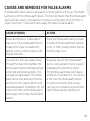
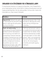
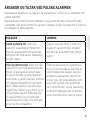
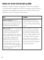
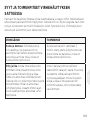
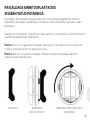
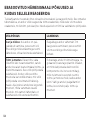
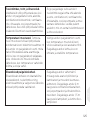
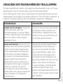
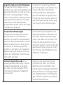
CAUSES AND REMEDIES FOR FALSE ALARMS
A smoke alarm device detects and reacts to smoke particles in the air. The smoke
particles set o the smoke alarm device. This function means that the smoke alarm
device will also react to dust particles, moisture or other particles in the form of
pollen, insects etc. These factors are usually the cause of a false alarm.
CAUSE OF ERROR ACTION
Steam and moisture. A false alarm
may occur if the smoke alarm device
is placed too close to a bathroom,
laundry room, or other location with
high air humidity.
Place the smoke alarm device at least
3 metres from any bathroom, laundry
room, or other location where high air
humidity may occur.
Dust and dirt. Since air passes freely
through the detection chamber, the
smoke alarm device will always attract
some dust and pollen particles. This
can lead to a false alarm. The smoke
alarm device may also become more
sensitive for this reason, which could
cause false alarms. In addition, dirt will
collect over time, as the smoke alarm
device ages, which may result in false
alarms.
Regularly vacuum the smoke alarm
device, using a plastic nozzle to avoid
damaging the electronics. Avoid
fitting smoke alarm devices in places
with a lot of dust and dirt. You can put
a ‘hat’ over the smoke alarm device
or remove it entirely while you are
carrying out renovation work at home
that involves sawing, sanding, etc.

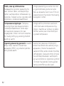
20
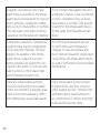
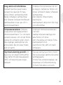
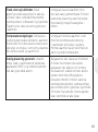
Draughts, dust and air flows. False
alarms may be caused by the smoke
alarm device being placed too close to
doors, windows, ventilation systems,
fans, air ducts, heat pumps or suchlike.
This can lead to dust particles being
carried up into the detection chamber.
Do not install smoke alarm devices in
a draughty location, close to windows
or doors, ventilation, fans, air ducts,
heat pumps or suchlike. Find a better
location for the smoke alarm device,
further away from draughts and air
flows.
Temperature variations. Temperature
variations may lead to condensation
in the detection chamber. This may
happen, for example, if the smoke
alarm device is placed in a room
where windows are opened for ven-
tilation in the winter, or close to exits,
balcony doors or other places that
switch between hot and cold.
Avoid fitting smoke alarm devices
in rooms with rapid temperature
changes or close to windows and
doors that are frequently opened and
closed. Move the smoke alarm device
to a place with a more even and stable
temperature.
Generally unfavourable positions.
Incorrect positioning in an unstable
indoor environment, a draughty area,
close to electronic apparatus (EMC)
and lighting may cause a false alarm.
Place smoke alarm devices at least
6 metres from open fires, stoves or
other heating devices; 2 metres from
ventilation ducts, heat pumps and
air conditioning; 1,5 metres from light
bulbs and fluorescent tubes.
Seite wird geladen ...
Seite wird geladen ...
Seite wird geladen ...
Seite wird geladen ...
Seite wird geladen ...
Seite wird geladen ...
Seite wird geladen ...
Seite wird geladen ...
Seite wird geladen ...
Seite wird geladen ...
Seite wird geladen ...
Seite wird geladen ...
Seite wird geladen ...
Seite wird geladen ...
Seite wird geladen ...
Seite wird geladen ...
Seite wird geladen ...
Seite wird geladen ...
Seite wird geladen ...
Seite wird geladen ...
Seite wird geladen ...
Seite wird geladen ...
Seite wird geladen ...
Seite wird geladen ...
Seite wird geladen ...
Seite wird geladen ...
Seite wird geladen ...
Seite wird geladen ...
Seite wird geladen ...
Seite wird geladen ...
Seite wird geladen ...
Seite wird geladen ...
Seite wird geladen ...
Seite wird geladen ...
Seite wird geladen ...
Seite wird geladen ...
Seite wird geladen ...
Seite wird geladen ...
Seite wird geladen ...
Seite wird geladen ...
Seite wird geladen ...
Seite wird geladen ...
Seite wird geladen ...
Seite wird geladen ...
Seite wird geladen ...
Seite wird geladen ...
Seite wird geladen ...
Seite wird geladen ...
Seite wird geladen ...
Seite wird geladen ...
Seite wird geladen ...
Seite wird geladen ...
Seite wird geladen ...
Seite wird geladen ...
Seite wird geladen ...
Seite wird geladen ...
Seite wird geladen ...
Seite wird geladen ...
Seite wird geladen ...
Seite wird geladen ...
Seite wird geladen ...
Seite wird geladen ...
Seite wird geladen ...
Seite wird geladen ...
Seite wird geladen ...
Seite wird geladen ...
Seite wird geladen ...
Seite wird geladen ...
Seite wird geladen ...
Seite wird geladen ...
Seite wird geladen ...
Seite wird geladen ...
Seite wird geladen ...
Seite wird geladen ...
Seite wird geladen ...
Seite wird geladen ...
Seite wird geladen ...
Seite wird geladen ...
Seite wird geladen ...
Seite wird geladen ...
Seite wird geladen ...
Seite wird geladen ...
Seite wird geladen ...
Seite wird geladen ...
Seite wird geladen ...
Seite wird geladen ...
Seite wird geladen ...
Seite wird geladen ...
Seite wird geladen ...
Seite wird geladen ...
Seite wird geladen ...
Seite wird geladen ...
Seite wird geladen ...
Seite wird geladen ...
Seite wird geladen ...
Seite wird geladen ...
Seite wird geladen ...
Seite wird geladen ...
Seite wird geladen ...
Seite wird geladen ...
Seite wird geladen ...
Seite wird geladen ...
Seite wird geladen ...
Seite wird geladen ...
Seite wird geladen ...
Seite wird geladen ...
Seite wird geladen ...
Seite wird geladen ...
Seite wird geladen ...
Seite wird geladen ...
Seite wird geladen ...
Seite wird geladen ...
Seite wird geladen ...
Seite wird geladen ...
Seite wird geladen ...
Seite wird geladen ...
Seite wird geladen ...
Seite wird geladen ...
Seite wird geladen ...
Seite wird geladen ...
Seite wird geladen ...
Seite wird geladen ...
Seite wird geladen ...
Seite wird geladen ...
Seite wird geladen ...
Seite wird geladen ...
Seite wird geladen ...
Seite wird geladen ...
Seite wird geladen ...
Seite wird geladen ...
Seite wird geladen ...
Seite wird geladen ...
-
 1
1
-
 2
2
-
 3
3
-
 4
4
-
 5
5
-
 6
6
-
 7
7
-
 8
8
-
 9
9
-
 10
10
-
 11
11
-
 12
12
-
 13
13
-
 14
14
-
 15
15
-
 16
16
-
 17
17
-
 18
18
-
 19
19
-
 20
20
-
 21
21
-
 22
22
-
 23
23
-
 24
24
-
 25
25
-
 26
26
-
 27
27
-
 28
28
-
 29
29
-
 30
30
-
 31
31
-
 32
32
-
 33
33
-
 34
34
-
 35
35
-
 36
36
-
 37
37
-
 38
38
-
 39
39
-
 40
40
-
 41
41
-
 42
42
-
 43
43
-
 44
44
-
 45
45
-
 46
46
-
 47
47
-
 48
48
-
 49
49
-
 50
50
-
 51
51
-
 52
52
-
 53
53
-
 54
54
-
 55
55
-
 56
56
-
 57
57
-
 58
58
-
 59
59
-
 60
60
-
 61
61
-
 62
62
-
 63
63
-
 64
64
-
 65
65
-
 66
66
-
 67
67
-
 68
68
-
 69
69
-
 70
70
-
 71
71
-
 72
72
-
 73
73
-
 74
74
-
 75
75
-
 76
76
-
 77
77
-
 78
78
-
 79
79
-
 80
80
-
 81
81
-
 82
82
-
 83
83
-
 84
84
-
 85
85
-
 86
86
-
 87
87
-
 88
88
-
 89
89
-
 90
90
-
 91
91
-
 92
92
-
 93
93
-
 94
94
-
 95
95
-
 96
96
-
 97
97
-
 98
98
-
 99
99
-
 100
100
-
 101
101
-
 102
102
-
 103
103
-
 104
104
-
 105
105
-
 106
106
-
 107
107
-
 108
108
-
 109
109
-
 110
110
-
 111
111
-
 112
112
-
 113
113
-
 114
114
-
 115
115
-
 116
116
-
 117
117
-
 118
118
-
 119
119
-
 120
120
-
 121
121
-
 122
122
-
 123
123
-
 124
124
-
 125
125
-
 126
126
-
 127
127
-
 128
128
-
 129
129
-
 130
130
-
 131
131
-
 132
132
-
 133
133
-
 134
134
-
 135
135
-
 136
136
-
 137
137
-
 138
138
-
 139
139
-
 140
140
-
 141
141
-
 142
142
-
 143
143
-
 144
144
-
 145
145
-
 146
146
-
 147
147
-
 148
148
-
 149
149
-
 150
150
-
 151
151
-
 152
152


in anderen Sprachen
- English: HOUSEGARD SA703 User manual
- dansk: HOUSEGARD SA703 Brugermanual
- eesti: HOUSEGARD SA703 Kasutusjuhend
- svenska: HOUSEGARD SA703 Användarmanual
Verwandte Artikel
Andere Dokumente
-
Smartwares RM175RF Benutzerhandbuch
-
Abus RM 04 Li VdS Radio Datenblatt
-
BRIGHT 024673 Benutzerhandbuch
-
Abus FURM50000 Bedienungsanleitung
-
Hard Head 014100 Benutzerhandbuch
-
Gira 2330 02 Installation and User Manual
-
HQ SEC-SA301RF Spezifikation
-
Smartwares RM220 Benutzerhandbuch
-
Honeywell Home R200ST-N1 Benutzerhandbuch