Audiotec Fischer HELIX H 400X Bedienungsanleitung
- Typ
- Bedienungsanleitung

4-Channel High End Amplifier
GERMANY
BEDIENUNGSANLEITUNG
INSTRUCTION MANUAL
deutsch/english
H 400X
BA_H400X.qxp 31.03.2010 11:41 Uhr Seite 1

2
Sehr geehrter Kunde,
wir gratulieren Ihnen zum Kauf dieser hochwertigen HELIX-
Endstufe. Diese Verstärker wurden nach neuesten techni-
schen Erkenntnissen entwickelt und zeichnen sich durch
hervorragende Verarbeitung und überzeugende Techno-
logie aus. Nach mehr als 30 Jahren Erfahrung in der
Erforschung und Entwicklung von Audiokomponenten setzt
sie neue Maßstäbe in puncto Preis-Leistungsverhältnis. Das
neue kräftige HELIX Design macht sie zu einer außerge-
wöhnlichen, leistungsstarken Endstufe der Spitzenklasse.
Viel Freude an diesem Produkt wünscht Ihnen das Team
von
AUDIOTEC FISCHER
Allgemeines zum Einbau von HELIX-Verstärkern
Um alle Möglichkeiten optimal ausschöpfen zu können, lesen Sie
bitte sorgfältig die nachfolgenden Installationshinweise. Wir
garantieren, dass jedes Gerät vor Versand auf seinen einwand-
freien Zustand überprüft wurde.
Vor Beginn der Installation unterbrechen Sie den Minusanschluss
der Autobatterie. Wir empfehlen Ihnen die Installation von einem
Einbauspezialisten vornehmen zu lassen, da der Nachweis eines
fachgerechten Einbaus und Anschlusses des Gerätes
Voraussetzung für die Garantieleistungen sind.
Installieren Sie Ihren Verstärker an einer trockenen Stelle im Auto
und vergewissern Sie sich, dass der Verstärker am Montageort
genügend Kühlung erhält. Montieren Sie das Gerät nicht in zu klei-
ne, abgeschlossene Gehäuse ohne Luftzirkulation oder in der
Nähe von wärmeabstrahlenden Teilen oder elektronischen
Steuerungen des Fahrzeuges.
Im Sinne der Unfallsicherheit muß der Verstärker professionell
befestigt werden. Dieses geschieht über die 4 beiliegenden
Schrauben, die in eine Montagefläche eingeschraubt werden, die
genügend Halt bieten muss. Bevor Sie die Schrauben im
Montagefeld befestigen, vergewissern Sie sich, daß keine elektri-
schen Kabel und Komponenten, hydraulische Bremsleitungen, der
Benzintank etc. dahinter verborgen sind. Diese könnten sonst
beschädigt werden. Achten Sie darauf, daß solche Teile sich auch
in der doppelten Wandverkleidung verbergen können.
Allgemeines zum Anschluss der Verstärker
Der Verstärker darf nur in Kraftfahrzeuge eingebaut werden, die
den 12V Minuspol an Masse haben. Bei anderen Systemen kön-
nen der Verstärker und die elektrische Anlage
des Kfz beschädigt werden.
Die Plusleitung für die gesamte Anlage sollte in einem Abstand
von max. 30 cm von der Batterie mit einer Hauptsicherung abge-
sichert werden. Der Wert der Sicherung errechnet sich aus der
maximalen Stromaufnahme der Car-Hifi Anlage. Die
Kabelverbindungen müssen so verlegt sein, dass keine Klemm-,
Quetsch-oder Bruchgefahr besteht. Bei scharfen Kanten
(Blechdurchführungen) müssen alle Kabel gegen Durchscheuern
gepolstert sein.
Ferner dürfen die Stromversorgungskabel niemals mit
Zuleitungen zu Vorrichtungen des Kfz (Lüftermotoren,
Brandkontrollmodulen, Benzinleitungen etc.) verlegt werden.
Um eine sichere Installation zu gewährleisten, sollte auf hohe
Qualität der verwendeten Anschlussmaterialien geachtet werden.
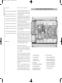
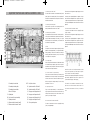
AUSSTATTUNG UND BEDIENELEMENTE H 400X
DEUTSCH
Anschluss Remoteleitung
Anschluss Batteriekabel
Anschluss Massekabel
Sicherungen 2 x 25 Ampere
Signaleingänge
Levelregler für Eingangsempfindlichkeit
Schalter für Signaleingänge
Schalter für die Kanäle A und B
Schalter für die Kanäle C und D
Mono/Stereo Schalter
Lautsprecheranschlussklemmen A/B
Lautsprecheranschlussklemmen C/D
Regler für den Hochpass Kanäle A/B
Regler für den Tiefpass Kanäle A/B
Regler für den Hochpass Kanäle C/D
Regler für den Tiefpass Kanäle C/D
Colour protection system
1
2
3
4
5-8
9-12
13
14
15
16-17
18
19
20
21
22
23
24
5
6
7
8
13
16
17
3
2
1
9
10
11
12
4
24
14
15
20
21
22
23
A
18
B
C
D
19
BA_H400X.qxp 31.03.2010 11:41 Uhr Seite 2

1 Anschluss Remoteleitung
Die Remoteleitung wird mit dem automatischen Antennen-
anschluss des Steuergerätes (Radio) verbunden. Dieser ist nur
aktiviert, wenn das Steuergerät EIN-geschaltet ist. Somit
wird der
Verstärker mit dem Steuergerät ein-und ausgeschaltet.
2 Anschluss Batteriekabel
Das +12V-Versorgungskabel ist am Pluspol der Batterie anzusch-
ließen. Empfohlener Querschnitt: min. 16 mm2.
3 Anschluss Massekabel
Das Massekabel sollte am zentralen Massepunkt (dieser befindet
sich dort wo der Minuspol der Batterie zum Metallchassis des Kfz
geerdet ist) oder an einer blanken, von Lack
resten befreiten Stelle
des Kfz-Chassis angeschlossen werden.
4 Sicherungen
Die Eingangssicherungen sind parallel geschaltet und schützen
vor einem geräteinternen Fehler, d. h. die Anlage muß mit einer
zusätzlichen Sicherung in Nähe der Batterie (max. 30 cm entfernt)
abgesichert werden. Die Sicherungswerte betragen 2 x 25 Ampere.
5 - 8 Signaleingänge
Der H 400X Verstärker hat RCA-Anschlüsse zum Kontaktieren von
Cinchkabeln, die mit den Vorverstärkerausgängen der Line-
Outputs des Steuergerätes oder eines Vorverstärkers verbunden
werden. Diese Anschlüsse sind
vergoldet um eine bessere NF-
Übertragung zu gewährleisten.
9 - 12 Levelregler für Eingangsempfindlichkeit
Mit Hilfe dieser Regler kann die Eingangsempfindlichkeit der ein-
zelnen Kanäle A bis D an die Ausgangsspannung des angeschlos-
senen Steuergerätes angepasst werden. Diese Regler sind keine
Lautstärkeregler, sondern dienen nur der Anpassung. Der
Regelbereich ist 700 mV - 8 V.
13 Schalter für Signaleingänge
Sollte nur ein Stereosignal, d. h. zwei Cinchleitungen zur
Verfügung stehen, können die Eingänge mit Hilfe dieses Schalters
(Schalterstellung 2) von A nach C und von B nach D verbunden
werden. Auf Schalterstellung 1 sind alle Eingänge getrennt.
14 Umschalter für die Kanäle A und B
Zur Umschaltung der internen, aktiven Frequenzweiche auf
Hochpass, Fullrange (Linear) oder Tiefpass/Bandpass. Wird dieser
Schalter auf Hochpass gestellt, so kann mit Hilfe des Reglers 20
die exakte Frequenz eingestellt werden.
Bei der Schalterstellung Tiefpass/Bandpass ist der Hochpass
immer aktiv. Das heißt, es wird in jedem Fall ein Bandpass gebil-
det. Mit dem Regler 20 wird der Hochpass und mit dem Regler
21der Tiefpass eingestellt. So kann jeder beliebige Bandpass zwi-
schen 15 Hz und 4000 Hz eingestellt werden.
15 Schalter für die Kanäle C und D
Zur Umschaltung der internen, aktiven Frequenzweiche auf
Hochpass, Fullrange (Linear) oder Tiefpass/Bandpass. Wird dieser
Schalter auf Hochpass gestellt, so kann mit Hilfe des Reglers 22
die exakte Frequenz eingestellt werden.
Bei der Schalterstellung Tiefpass/Bandpass ist der Hochpass
immer aktiv. Das heißt, es wird in jedem Fall ein Bandpass gebil-
det. Mit dem Regler 22 wird der Hochpass und mit dem Regler
23der Tiefpass eingestellt. So kann jeder beliebige Bandpass zwi-
schen 15 Hz und 4000 Hz eingestellt werden.
Achtung! Bitte vergewissern Sie sich, dass beim Einstellen
eines Bandpasses die Übernahmefrequenzen von Hoch-
und Tiefpass 2 Oktaven auseinander liegen, um
Pegelverlust zu vermeiden!
Das heisst: Wird das Tiefpasssignal z. B. auf 320 Hz eingestellt,
so sollte der Hochpass um 2 Oktaven tiefer auf ca. 80 Hz einge-
stellt werden (1 Oktave = Frequenzverdopplung oder -halbierung).
Beim Anschluss eines Basslautsprechers empfiehlt es sich, die
Hochpassregler 20 und 22 als regelbaren Subsonicfilter zu benut-
zen oder auf Linksanschlag 15 Hz zu drehen, um so einen
Subsonivfilter zu erhalten.
16 - 17 Mono/Stereo Schalter
Mit diesen Schaltern kann die Betriebsart der Endstufe festgelegt
werden. Nutzen Sie den Verstärker im 4-Kanalbetrieb, so müssen
sich beide Schalter in Stereo-Position befinden (Position 1).
Nutzen Sie den Verstärker im 3-Kanalbetrieb (Frontsystem/
Woofer), stellen Sie den Schalter für das Frontsystem auf Stereo
und den Schalter für den Subwoofer auf Mono (Position 2).
Achtung:
Die Impedanz des Woofers darf im Brückenbetrieb 4 Ohm nicht
unterschreiten.
3
18 Lautsprecheranschlussklemmen für Kanäle A und B
Zum Anklemmen der Lautsprecherleitungen.
19 Lautsprecheranschlussklemmen für Kanäle C und D
Zum Anklemmen der Lautsprecherleitungen.
Verbinden Sie niemals die Lautsprecherleitungen mit der Kfz-
Masse (Fahrzeugkarosserie). Dieses kann Ihren Verstärker
zerstören.
Achten Sie darauf, dass alle Lautsprechersysteme
phasenrichtig angeschlossen sind, d.h. Plus zu Plus und Minus zu
Minus. Vertauschen von Plus und Minus hat einen Totalverlust
der Basswiedergabe zu Folge.Der Pluspol ist bei den meisten
Lautsprechern gekennzeichnet.
Die Impedanz pro Kanal sollte 2 Ohm nicht unterschreiten, da
sonst eine zu hohe Wärmeentwicklung den Verstärker zum
Abschalten bringen kann.
20 Frequenzeinstellregler für den Hochpass Kanäle A und B
Regler zur Einstellung der Trennfrequenz von 15Hz - 4 kHz.
21 Frequenzeinstellregler für den Tiefpass Kanäle A und B
Regler zur Einstellung der Trennfrequenz von 15Hz - 4 kHz.
22 Frequenzeinstellregler für den Hochpass Kanäle C und D
Regler zur Einstellung der Trennfrequenz von 15Hz - 4 kHz.
23 Frequenzeinstellregler für den Tiefpass Kanäle C und D
Regler zur Einstellung der Trennfrequenz von 15Hz - 4 kHz.
24 CPS - Colour Protection System
Die LEDs zeigen den Betriebszustand der Endstufe an: Grün=
betriebsbereit, Gelb=Fehlfunktion der Endstufe. Kurzschluss am
Lautsprecherausgang: Rot=Überhitzung. Sollte die Endstufe
wegen Überhitzung abschalten, kann es je nach
Umgebungstemperatur einige Zeit dauern, bis sie sich wieder ein-
schaltet.
BA_H400X.qxp 31.03.2010 11:41 Uhr Seite 3

Helix Produkte geniessen aufgrund ihres hohen Qualitätsniveaus
international einen ausgezeichneten Ruf. Daher gewähren wir
eine Garantiezeit von 2 Jahren.
Die Produkte werden während der gesamten Fertigung ständig
kontrolliert und geprüft. Bitte beachten Sie im Servicefall folgen-
de Hinweise:
1. Die 2-jährige Garantiezeit beginnt mit Kauf des Produktes
und gilt nur für den Erstbesitzer.
2.
Während der Garantiezeit beseitigen wir etwaige Mängel,
die
nachweislich auf Material- oder Fabrikationsfehlern beru-
hen, nach unserer Wahl durch Austausch oder Nach-
besserung der defekten Teile. Weitergehende Ansprüche,
insbesondere auf Minderung, Wandlung, Schadenersatz oder
Folgeschäden sind ausgeschlossen. Ersetzte Teile gehen in
das Eigentum von Audiotec Fischer über. Die Garantiezeit
wird von einer Garantieleistung durch uns nicht berührt.
3. Am Produkt dürfen keine unsachgemäßen Eingriffe vorge-
nommen worden sein.
4. Bei Inanspruchnahme der Garantie wenden Sie sich bitte
zuerst an Ihren Fachhändler. Sollte es notwendig sein, das
Produkt an uns einzuschicken, so beachten Sie bitte folgen-
de Hinweise:
a) Das Produkt muss in einwandfreier Originalverpackung
verschickt werden.
b)
Die Garantiekarte muss ausgefüllt dem Produkt beiligen.
c) Das Produkt muss frachtfrei zugestellt werden, d.h.
Porto und Risiko gehen zu Ihren Lasten
d) Die Kaufquittung muss beiliegen.
5. Von der Garantie ausgenommen sind:
a) Transportschäden, sichtbar oder unsichtbar (Reklama-
tionen für solche Schäden müssen umgehend bei der
Transportfirma eingereicht werden)
b) Kratzer in Metallteilen, Frontabdeckungen usw. Diese
Defekte müssen innerhalb von 5 Tagen nach Kauf direkt
bei Ihrem Händler reklamiert werden.
c) Fehler, die durch fehlerhafte Aufstellung, falschen
An-
schluss, unsachgemäße Bedienung, Beanspruchung
oder
äußere gewaltsame Einwirkung entstanden sind.
d) Unsachgemäß reparierte oder geänderte Geräte, die von
anderer Seite als von uns geöffnet wurden.
e) Folgeschäden an fremden Geräten
f) Kostenerstattung bei Schadensbehebung durch Dritte
ohne unser vorheriges Einverständnis
g) Geräte mit entfernten Typenschildern oder Seriennummern.
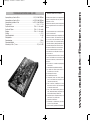
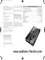
TECHNISCHE DATEN PRECISION H 400X GARANTIEBESTIMMUNGEN
Ausgangsleistung pro Kanal an 4 Ohm . . . . . . . . . . . . . . . . . . . . . . . . . . 4 x 70/140 Watt RMS/Musik
Ausgangsleistung pro Kanal an 2 Ohm . . . . . . . . . . . . . . . . . . . . . . . . . 4 x 125/250 Watt RMS/Musik
Ausgangsleistung gebrückt an 4 Ohm . . . . . . . . . . . . . . . . . . . . . . . . . . 2 x 250/500 Watt RMS/Musik
Frequenzbereich . . . . . . . . . . . . . . . . . . . . . . . . . . . . . . . . . . . . . . . . . . . . . . . . . 20 Hz - 20 000 Hz
Regelbereich Hochpass . . . . . . . . . . . . . . . . . . . . . . . . . . . . . . . . . . . . . . 15 Hz - 4 000 Hz regelbar
Regelbereich Tiefpass . . . . . . . . . . . . . . . . . . . . . . . . . . . . . . . . . . . . . . . 15 Hz - 4 000 Hz regelbar
Bandpass . . . . . . . . . . . . . . . . . . . . . . . . . . . . . . . . . . . . . . . . . . . . . . . . . .15 Hz - 4 000 Hz regelbar
Klirrfaktor . . . . . . . . . . . . . . . . . . . . . . . . . . . . . . . . . . . . . . . . . . . . . . . . . . . . . . . . . . . . < 0,009 %
Signal-/Rauschabstand . . . . . . . . . . . . . . . . . . . . . . . . . . . . . . . . . . . . . . . . . . . . . . . . . . . > 100 dB
Dämpfungsfaktor . . . . . . . . . . . . . . . . . . . . . . . . . . . . . . . . . . . . . . . . . . . . . . . . . . . . . . . . . > 300
Eingangsimpedanz . . . . . . . . . . . . . . . . . . . . . . . . . . . . . . . . . . . . . . . . . . . . . . . . . . . . . . .10 kOhm
Eingangsempfindlichkeit . . . . . . . . . . . . . . . . . . . . . . . . . . . . . . . . . . . . . . . . . . . . . . . . . . 0,7 - 8,0 V
Abmessungen (H x B x T) in mm . . . . . . . . . . . . . . . . . . . . . . . . . . . . . . . . . . . . . . 31,5 x 200 x 336
4
www.audiotec-fischer.com
BA_H400X.qxp 31.03.2010 11:41 Uhr Seite 4

5
Dear Customer,
congratulations on your purchase of this high-quality
HELIX- amplifier. This series highlights best quality, excel-
lent manufacturing and state-of-the-art technology. After
30 years of experiences in the research & development of
audio products this amplifier generation sets new stan-
dards. The attractive typical HELIX design makes this
amplifier an outstanding and top of the class product.
We wish you many hours of enjoyment with your new
HELIX amplifier.
Yours
AUDIOTEC FISCHER Team
General installation instructions for HELIX amplifiers
To find out how HELIX amplifiers work best for you, read this
manual carefully and follow the instructions for installation. We
guarantee that this product has been checked for proper functio-
ning before shipping.
Before you start installation, disconnect the car battery at the
minus pole. We would urge you to have the installation work car-
ried out by a specialist as verification of correct installation and
connection of the unit is a prerequisite for warranty cover of the
HELIX amplifier.
Install your amplifier at a dry location where there is sufficient air
circulation to ensure adequate cooling of the equipment. For
safety reasons, the amplifier must be secured in a professional
manner. This is performed by means of four fixing screws scr-
ewed into a mounting surface offering sufficient retention and
stability.
Before drilling the holes for the screws, carefully examine the area
around the installation position and make sure that there are no
electrical cables or components, hydraulic brake lines or any part
of the petrol tank located behind the mounting surface - otherwi-
se these could be damaged. You should be aware of the fact that
such components may also be concealed in the double-skin trim
panels/mouldings.
General instruction for connecting the amplifiers
The HELIX amplifiers may only be installed in motor vehicles
which have a 12-volt minus pole connected to the chassis ground.
Any other system could cause damage to the amplifier and the
electrical system of the vehicle.
The plus cable from the battery for the complete system should be
provided with a main fuse at a distance of max. 30 cm from the
battery. The value of the fuse is calculated from the maximum total
current input of the car audio system.
Install the cabling in a manner which precludes any danger of the
leads being exposed to shear, crushing or rupture forces. If there are
sharp edges in the vicinity (e.g. holes in the bodywork) all cables
must be cushioned and protected to prevent fraying.
Never lay the power supply cables adjacent to leads and lines
connecting other vehicle equipment (fan motors, fire detection
modules, gas lines etc.).
In order to ensure safe installation, use only high-quality connections
and materials. Ask your dealer for high quality accessories.
ENGLISH
Due to the high quality standard Helix products achieved an
excellent international reputation. Therefore we grant a warran-
ty period of 2 years.
The products checked and tested carefully during the entire pro-
duction process. In the case of service note the following:
1) The 2 years warranty period commences with the purchase of
the product and is applicable only to the original owner.
2) During the warranty period we will rectify any defects
due to faulty material or workmanship by replacing or repai
ring the defective part at our decission.
Further claims, and in particular those for price reduction,
cancellation of sale, compensation for damages or subse
quential damages, are excluded. The warranty period is not
altered by the fact that we have carried out warranty work.
3) Unauthorized tampering with the product will invalidate this
warranty.
4) Consult your authorized dealer first, if warranty service is nee-
ded. Should it be necessary to return the product to the fac-
tory, please insure that
a) the product is packed in original factory packing in
good condition
b) the warranty card has been filled out and attached to the
product
c) the product is shipped prepaid, i.e. at your expense
and risk
d) the receipt/invoice as proof of purchase is enclosed
5) Excluded from the warranty are:
a) Shipping damages, either readily apparent or concea-
led (claims for such damages must be immediately
notified to the forwarding agent).
b) Scratches in metal parts, front panels or covers etc.
This must be notified to your dealer within 5 days of purchase.
c) Defects caused by incorrect installation or connec-
tion, by operation errors, by overloading or by external force.
d) Products which have been repaired incorrectly or
modified or where the product has been opened by
other persons than us.
e) Consoquential damages to other equipments.
f) Reimbursement when repairing damages by third
parties without our previous permission.
WARRANTY REGULATION
BA_H400X.qxp 31.03.2010 11:41 Uhr Seite 5

6
EQUIPMENT FEATURES AND CONTROL ELEMENTS H 400X
If this switch is set on Highpass the exactly frequency can be set
with control No. 20.
At switch position lowpass/bandpass the highpass is always
active. That means a Bandpass is built in any case. With control
20 adjust the highpass and with control 21 adjust the lowpass.
Thus every desired bandpass between 15 Hz and 4000 Hz can be
adjusted.
15 Selector switch for channels C and D
To switch the internal active crossover to highpass/full range
(linear) or lowpass.
If this switch is set on Highpass the exactly frequency can be set
with control No. 22.
At switch position lowpass/bandpass the highpass is always
active. That means a bandpass is built in any case. With control
22 adjust the highpass and with control 23 adjust the lowpass.
Thus every desired Bandpass between 15 Hz and 4000 Hz can be
adjusted.
Caution! To avoid a lost of sound pressure make sure that
the crossover frequencies of high- and lopass are separa-
ted of 2 octaves when building a bandpass.
That means: If the lowpass signal is adjusted to 320 Hz the high-
pass should be adjusted 2 octaves lower on approx. 80 Hz
(1 octave=double frequency or half frequency).
If a subwoofer is connected we recommend to use high-
pass controls 20 and 22 as variable subsonic filter or to
turn them counter-clockwise to 15 Hz to get a subsonic
filter.
Connecting the remote lead
Connecting the battery cable
Connecting the ground cable
Fuses 2 x 25 Ampere
Signal inputs
Level controls for input sensitivity
Signal input selector
Selector switch for channels A and B
Selector switch for channels C and D
Mono/Stereo selector
Speaker terminals for CH A and B
Speaker terminals for CH C and D
Frequency control highpass A and B
Frequency control lowpass A and B
Frequency control highpass C and D
Frequency control lowpass C and D
Colour protection system
1
2
3
4
5-8
9-12
13
14
15
16-17
18
19
20
21
22
23
24
1 Connecting the remote lead
The remote lead is connected to the automatic antenna (aerial
positive) output of the head unit (radio). This is only activated if
the head unit is switched ON. Thus the amplifier is switched on
and off with the head unit.
2 Connecting the battery cable
Connect the +12 V power cable to the positive terminal of the
battery. Recommended cross section: min. 16mm2.
3 Connecting the ground cable
The ground cable should be connected to a central ground refe-
rence point (this is located where the negative terminal of the bat-
tery is grounded at the metal body of the vehicle), or to a bright
bare-metal location on the vehicle chassis, i.e. an area which has
been cleaned of all paint residues.
4 Fuses
The input fuses are connected in parallel and provide protection
against an internal equipment fault, i.e. the system must be addi-
tionally protected by a further line fuse located in the vicinity of
the battery (max. distance from battery: 30 cm). The fuse rating
is 2 x 25 ampere for both amplifiers.
5 - 8 Signal inputs
The H 400X amplifier has RCA connectors for RCA cables that can
be connected with the pre-amplifier output of the line-outputs of
the headunit or with a pre-amplifier. This connectors are gold-pla-
ted to ensure a better signal transmission.
9 - 12 Level controls for input sensitivity
These controls can be used to match the input sensitivity of the
individual channels to the output voltage of the connected head
unit. These controls are not volume controls and are solely inten-
ded for the purpose of sensitivity trimming. The control range
extends from 700 mV to 8 V.
13 Signal input selector
If only one stereo signal is available (i. e. 2 cinch leads connec-
ted), the inputs can be connected from A to C and from B to D by
setting the selector switch to position 2. When selector is set to
position 1, all the inputs are separate.
14 Selector switch for channels A and B
To switch the internal active crossover to highpass/full range
(linear) or lowpass/bandpass.
5
6
7
8
13
16
17
3
2
1
9
10
11
12
4
24
14
15
20
21
22
23
A
18
B
C
D
19
BA_H400X.qxp 31.03.2010 11:41 Uhr Seite 6

7
16 - 17 Mono/Stereo selector
For switching the amplifier into 4-channel operation mode both
switches must be in stereo position (position 1). To use the amp
in 3-channel mode (front / sub), the front channel has to be set
in stereo and the sub channel to mono (position 2).
Warning:
The impedance of the woofer in bridged mode must not be lower
than 4 Ohms!
18 Speaker terminals for channels A and B
To connect the speaker cables.
19 Speaker terminals for channels C and D
To connect the speaker cables.
Never connect the speaker wires to the chassis of the vehicle.
This can destroy your amplifier. All speaker systems must be con-
nencted in-phase, this means plus to plus and minus to minus.
The plus pole is normally marked on the speaker. In addition, the
amplifire can operate channels A and B as well as C and D in
stereo or mono mode (bridged).
The impedance per channel should not be lower than 2 Ohms.
20 Frequency level control for highpass of CH A and B
Control for the adjustment of the crossover frequency from 15Hz
to 4 kHz.
21 Frequency level control for lowpass of CH A and B
Control for the adjustment of the crossover frequency from 15Hz
to 4 kHz.
TECHNICAL DATA PRECISION P400
Cont. power rating at 4 Ohms per channel . . . . . . . . . . . . . . . . . . . . . . . 4 x 70/140 Watt RMS/Music
Cont. power rating at 2 Ohms per channel . . . . . . . . . . . . . . . . . . . . . . 4 x 125/250 Watt RMS/Music
Cont. power rating bridged at 2 Ohms per channel . . . . . . . . . . . . . . . . 2 x 250/500 Watt RMS/Music
Frequency response . . . . . . . . . . . . . . . . . . . . . . . . . . . . . . . . . . . . . . . . . . . . . . 20 Hz - 20 000 Hz
Highpass . . . . . . . . . . . . . . . . . . . . . . . . . . . . . . . . . . . . . . . . . . . . . . . . . 15 Hz - 4 kHz adjustable
Lowpass . . . . . . . . . . . . . . . . . . . . . . . . . . . . . . . . . . . . . . . . . . . . . . . . . . 15 Hz - 4 kHz adjustable
Bandpass . . . . . . . . . . . . . . . . . . . . . . . . . . . . . . . . . . . . . . . . . . . . . . . . . 15 Hz - 4 kHz adjustable
Total harmonic distortion (THD) . . . . . . . . . . . . . . . . . . . . . . . . . . . . . . . . . . . . . . . . . . . . < 0,009%
Signal to noise ratio . . . . . . . . . . . . . . . . . . . . . . . . . . . . . . . . . . . . . . . . . . . . . . . . . . . . . > 100 dB
Damping factor . . . . . . . . . . . . . . . . . . . . . . . . . . . . . . . . . . . . . . . . . . . . . . . . . . . . . . . . . . . > 300
Input impedance . . . . . . . . . . . . . . . . . . . . . . . . . . . . . . . . . . . . . . . . . . . . . . . . . . . . . . . .10 kOhms
Input sensitivity . . . . . . . . . . . . . . . . . . . . . . . . . . . . . . . . . . . . . . . . . . . . . . . . . . . . . . . .0,7 - 8,0 V
Dimensions (H x W x D) mm . . . . . . . . . . . . . . . . . . . . . . . . . . . . . . . . . . . . . . . . . 31,5 x 200 x 336
22 Frequency level control for highpass of CH C and D
Control for the adjustment of the crossover frequency from 15Hz
to 4 kHz.
23 Frequency level control for lowpass of CH C and D
Control for the adjustment of the crossover frequency from 15Hz
to 4 kHz.
24 CPS - colour protection system
The LEDs show the operation status of the amp. Green=O.K.;
Yellow=the speakers wires are shorted to ground; Red=overhea-
ted. If the amp shuts off due to overheating it will take some
time (depending on the outside temperature) until it switches on
again.
www.audiotec-fischer.com
BA_H400X.qxp 31.03.2010 11:41 Uhr Seite 7

Gewerbegebiet Lake II · Hünegräben 26 · D-57392 Schmallenberg
Tel.: +49 (0) 29 72-97 88 0 · Fax: +49 (0) 29 72-97 88 88
E-mail: [email protected] · Internet: www.audiotec-fischer.com
BA_H400X.qxp 31.03.2010 11:41 Uhr Seite 8
-
 1
1
-
 2
2
-
 3
3
-
 4
4
-
 5
5
-
 6
6
-
 7
7
-
 8
8


Audiotec Fischer HELIX H 400X Bedienungsanleitung
- Typ
- Bedienungsanleitung
in anderen Sprachen
Verwandte Artikel
-
 Audiotec Fischer Helix Precision P400 Benutzerhandbuch
-
 Audiotec Fischer HELIX G FIVE Bedienungsanleitung
-
 Audiotec Fischer HELIX C FOUR Bedienungsanleitung
-
 Audiotec Fischer HELIX M FOUR Bedienungsanleitung
-
Helix HELIX P TWO Bedienungsanleitung
-
 Audiotec Fischer HELIX M SIX Bedienungsanleitung
-
 Audiotec Fischer HELIX D FOUR Bedienungsanleitung
-
 Audiotec Fischer HELIX HXA 1000 QX Benutzerhandbuch


