
IMPORTANT SAFETY INSTRUCTIONS
READ AND FOLLOW ALL INSTRUCTIONS
SAVE THESE INSTRUCTIONS
INSTALLATION AND
USER’S GUIDE
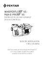
WHISPERFLOXF® VS AND
MAX-E-PROXF ® VS
COMMERCIAL VARIABLE SPEED PUMP

WHISPERFLOXF® VS and MAX-E-PROXF® VS Commercial Variable Speed Pump Installation and User’s Guide
i
IMPORTANT SAFETY INSTRUCTIONS
When installing and using this electrical equipment, basic safety
precautions should always be followed, include the following:
Do not permit children to use this product.
RISK OF ELECTRICAL SHOCK. The pump must
only be connected to sockets that have been installed
properly in accordance with the regulations and are protected with a FI-
safety switch (Residual-current device - RCD, 30mA).
This unit must be connected only to a supply circuit
that is protected by a ground-fault circuit-interrupter
(RCD). Such an RCD should be provided by the installer and should
be tested on a routine basis. To test the RCD, push the test button.
The RCD should interrupt power. Push the reset button. Power should
be restored. If the RCD fails to operate in this manner, the RCD is
defective. If the RCD interrupts power to the pump without the test button
being pushed, a ground current is flowing, indicating the possibility of an
electric shock. Do not use this pump. Disconnect the pump and have the
problem corrected by a qualified service representative before using.
This pump is for use with permanent swimming
pools and may also be used with hot tubs and spas if
so marked. Do not use with storable pools. A permanently-installed pool
is constructed in or on the ground or in a building such that it cannot be
readily disassembled for storage. A storable pool is constructed so that
it is capable of being readily disassembled for storage and reassembled
to its original integrity.
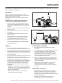
General Warnings
• Never open the inside of the drive motor enclosure. There is a
capacitor bank that holds a 230 VAC charge even when there is no
power to the unit.
• The pump is not submersible.
• The pump is capable of high flow rates; use caution when installing
and programming to limit pumps performance potential with old or
questionable equipment.
• Code requirements for electrical connection differ from country to
country, state to state, as well as local municipalities. Install equipment
in accordance with IEC 60364 (Low-voltage electrical installations),
IEC 60364-7-702 (Requirements for special installations or locations
- Swimming pools and other basins) and all applicable local codes
and ordinances.
• Before servicing the pump; switch OFF power to the pump by
disconnecting the main circuit to the pump.
• This appliance is not intended for use by persons (including children) of
reduced physical, sensory or mental capabilities, or lack of experience
and knowledge, unless they have been given supervision or instruction
concerning the use of the appliance by a person responsible for their
safety.
• Children should not be allowed to play with the appliance.
FAILURE TO FOLLOW ALL INSTRUCTIONS AND
WARNINGS CAN RESULT IN SERIOUS BODILY
INJURY OR DEATH. THIS PUMP SHOULD BE INSTALLED AND
SERVICED ONLY BY A QUALIFIED POOL SERVICE PROFESSIONAL.
INSTALLERS, POOL OPERATORS AND OWNERS MUST READ
THESE WARNINGS AND ALL INSTRUCTIONS IN THE OWNER’S
MANUAL BEFORE USING THIS PUMP. THESE WARNINGS AND
THE OWNER’S MANUAL MUST BE LEFT WITH THE POOL OWNER.
SUCTION ENTRAPMENT HAZARD: STAY OFF
THE MAIN DRAIN AND AWAY FROM ALL SUCTION
OUTLETS!
THIS PUMP PRODUCES HIGH LEVELS OF SUCTION AND CREATES
A STRONG VACUUM AT THE MAIN DRAIN AT THE BOTTOM OF THE
BODY OF WATER. THIS SUCTION IS SO STRONG THAT IT CAN TRAP
ADULTS OR CHILDREN UNDER WATER IF THEY COME IN CLOSE
PROXIMITY TO A DRAIN OR A LOOSE OR BROKEN DRAIN COVER
OR GRATE.
THE USE OF UNAPPROVED COVERS OR ALLOWING USE OF
THE POOL OR SPA WHEN COVERS ARE MISSING, CRACKED OR
BROKEN CAN RESULT IN BODY OR LIMB ENTRAPMENT, HAIR
ENTANGLEMENT, BODY ENTRAPMENT, EVISCERATION AND/OR
DEATH.
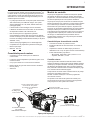
This guide provides installation and operation instructions
for this pump. Consult Pentair with any questions regarding
this equipment.
Attention Installer: This guide contains important information about the
installation, operation and safe use of this product. This information should
be given to the owner and/or operator of this equipment after installation
or left on or near the pump.
Attention User: This manual contains important information that will help
you in operating and maintaining this product. Please retain it for future
reference.
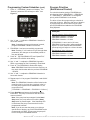
This is the safety alert symbol. When you see this
symbol on your system or in this manual, look for
one of the following signal words and be alert to
the potential for personal injury.
Warns about hazards that can cause death,
serious personal injury, or major property damage
if ignored.
Warns about hazards that may cause death,
serious personal injury, or major property damage
if ignored.
Warns about hazards that may or can cause minor
personal injury or property damage
if ignored.
NOTE Indicates special instructions not related to
hazards.
Carefully read and follow all safety instructions in this manual and on
equipment. Keep safety labels in good condition; replace if missing
or damaged.
READ AND FOLLOW ALL INSTRUCTIONS
SAVE THESE INSTRUCTIONS
IMPORTANT NOTICE
F

WHISPERFLOXF® VS and MAX-E-PROXF® VS Commercial Variable Speed Pump Installation and User’s Guide
ii
IMPORTANT SAFETY INSTRUCTIONS
For Installation of Electrical Controls at Equipment Pad (ON/OFF
Switches, Timers and Automation Load Center)
Install all electrical controls at equipment pad, such as
on/off switches, timers, and control systems, etc. to
allow the operation (startup, shut-down, or servicing)
of any pump or filter so the user does not place any
portion of his/her body over or near the pump strainer
lid, filter lid or valve closures. This installation should
allow the user enough space to stand clear of the filter
and pump during system start-up, shut down or servicing of the system filter.
HAZARDOUS PRESSURE: STAND CLEAR OF
PUMP AND FILTER DURING START UP
Circulation systems operate under high pressure.
When any part of the circulating system (i.e.
locking ring, pump, filter, valves, etc.) is serviced,
air can enter the system and become pressurized.
Pressurized air can cause the pump housing cover, filter lid, and valves
to violently separate which can result in severe personal injury or death.
Filter tank lid and strainer cover must be properly secured to prevent
violent separation. Stand clear of all circulation system equipment when
turning on or starting up pump.
Before servicing equipment, make note of the filter pressure. Be sure
that all controls are set to ensure the system cannot inadvertently start
during service. Turn off all power to the pump. IMPORTANT: Place filter
manual air relief valve in the open position and wait for all pressure
in the system to be relieved.
Before starting the system, fully open the manual air relief valve and place
all system valves in the “open” position to allow water to flow freely from the
tank and back to the tank. Stand clear of all equipment and start the pump.
IMPORTANT: Do not close filter manual air relief valve until all
pressure has been discharged from the valve and a steady stream
of water appears. Observe filter pressure gauge and be sure it is not
higher than the pre-service condition.
General Installation Information
• All work must be performed by a qualified service professional, and
must conform to all national, state, and local codes.
• Install to provide drainage of compartment for electrical components.
• These instructions contain information for a variety of pump models
and therefore some instructions may not apply to a specific model. All
models are intended for use in swimming pool applications. The pump
will function correctly only if it is properly sized to the specific application
and properly installed.
Pumps improperly sized or installed or used in
applications other than for which the pump was
intended can result in severe personal injury or death. These risks
may include but not be limited to electric shock, fire, flooding, suction
entrapment or severe injury or property damage caused by a structural
failure of the pump or other system component.
The pump can produce high levels of suction within
the suction side of the plumbing system. These
high levels of suction can pose a risk if a person comes within the close
proximity of the suction openings. A person can be seriously injured
by this high level of vacuum or may become trapped and drown. It is
absolutely critical that the suction plumbing be installed in accordance
with the latest national and local codes for swimming pools.
The suction at a drain or outlet can cause:
Limb Entrapment: When a limb is sucked or inserted into an opening
resulting in a mechanical bind or swelling. This hazard is present when
a drain cover is missing, broken, loose, cracked or not properly secured.
Hair Entanglement: When the hair tangles or knots in the drain cover,
trapping the swimmer underwater. This hazard is present when the flow
rating of the cover is too small for the pump or pumps.
Body Entrapment: When a portion of the body is held against the drain
cover trapping the swimmer underwater. This hazard is present when the
drain cover is missing, broken or the cover flow rating is not high enough
for the pump or pumps.
Evisceration/Disembowelment: When a person sits on an open pool
(particularly a child wading pool) or spa outlet and suction is applied directly
to the intestines, causing severe intestinal damage. This hazard is present
when the drain cover is missing, loose, cracked, or not properly secured.
Mechanical Entrapment: When jewelry, swimsuit, hair decorations, finger,
toe or knuckle is caught in an opening of an outlet or drain cover. This
hazard is present when the drain cover is missing, broken, loose, cracked,
or not properly secured.
NOTE: ALL SUCTION PLUMBING MUST BE INSTALLED IN
ACCORDANCE WITH THE LATEST NATIONAL AND LOCAL CODES,
STANDARDS AND GUIDELINES.
TO MINIMIZE THE RISK OF INJURY DUE TO
SUCTION ENTRAPMENT HAZARD:
• A properly installed and secured ANSI/ASME A112.19.8 approved
anti-entrapment suction cover must be used for each drain.
• Each suction cover must be installed at least 1 meter apart, as
measured from the nearest point to nearest point.
• Regularly inspect all covers for cracks, damage and advanced
weathering.
• If a cover becomes loose, cracked, damaged, broken or is missing,
replace with an appropriate certified cover.
• Replace drain covers as necessary. Drain covers deteriorate over
time due to exposure to sunlight and weather.
• Avoid getting hair, limbs or body in close proximity to any suction
cover, pool drain or outlet.
• Disable suction outlets or reconfigure into return inlets.
A clearly labeled emergency shut-off switch for the
pump must be in an easily accessible, obvious place.
Make sure users know where it is and how to use it in case of emergency.

WHISPERFLOXF® VS and MAX-E-PROXF® VS Commercial Variable Speed Pump Installation and User’s Guide
iii
Important Safety Instructions ..............................
Introduction ...........................................................
Motor Features
Drive Assembly and Keypad
Drive Features
External Control
Using the Drive Keypad .......................................
Installation .............................................................
Location
Piping
Fittings and Valves
Electrical Requirements
Electrical Installation
Wiring, Grounding and Bonding
External Control via RS-485
External Control via Digital Inputs
Using the Pump's Output Signal
Using an External Input Signal
External Control Only Mode
Operation ...............................................................
Setting the Clock and Pump Address
Using the Default Schedule
Programming Custom Schedules
Program Priorities (Non-External Control)
Priming the Pump
Priming Adjustment
Operating the Pump While Running
Programming Quick Clean
Keypad Lockout
Factory Reset
Operating the Pump in Flow Mode
Flow Mode Setup and Configuration
Adjusting Flow Setting
i
1
1
1
1
1
2
3
3
3
3
3
4
4
5
6
6
7
7
8
8
8
8
9
10
11
12
12
13
13
14
14
15
16
16
16
17
17
18
18
19
20
22
23
24
24
24
24
24
TABLE OF CONTENTS
If you have questions about ordering Pentair replacement parts, and pool products, please contact:
CUSTOMER SERVICE / TECHNICAL SUPPORT
Customer Service
Customer service PISA, ITALY (8:30 AM to 4:30 PM CET)
+39 050716166 / +39 050716169
orders.pooleu@pentair.com
poolemea@pentair.com
www.pentairpooleurope.com
Technical Support
e-mail: techsupport.poolemea@pentair.com
Hotline: +33 184280940
Maintenance ...........................................................
Cleaning the Pump Strainer Basket
Winterizing
Motor and Drive Care
Pump Disassembly
Shaft Seal Replacement
Pump Reassembly
Replacing the Drive Assembly
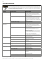
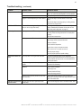
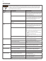
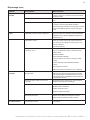
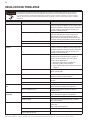
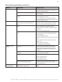
Troubleshooting ....................................................
Faults and Alarms
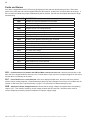
Replacement Parts ................................................
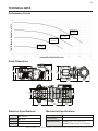
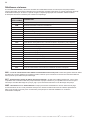
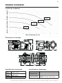
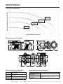
Technical Data .......................................................
Performance Curves
Pump Dimensions
Electrical Specifications
Mechanical Specifications
* Translated versions of this manual are available online at: https://www.pentairpooleurope.com/

WHISPERFLOXF® VS and MAX-E-PROXF® VS Commercial Variable Speed Pump Installation and User’s Guide
1
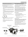
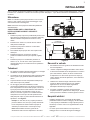
INTRODUCTION
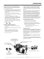
The WhisperFloXF® VS or Max-E-ProXF® VS
Commercial Variable Speed Pump can be programmed
to run at specic speeds and time intervals for maximum
operating eciency and energy conservation for a
variety of inground pools.
•The pump can operate at any speed between 300
RPM to 3450 RPM for dierent applications, with four
preset speeds of 1720, 2500, 3000 and 3450 (Quick
Clean).
•Alarm LED and error messages warn the user against
under and over voltage, high temperature and over
current, etc.
•Communicates with most Pentair automation systems
via the Digital Input Wiring Kit (P/N 353129Z- Almond)
or RS-485 Automation Wiring Kit (P/N 356324Z -
Black).
•Adjustable priming speed for easy start-up
•Compatible with most cleaning systems, lters, and
jet action spas
•WEF 5.0 THP 5.0
Motor Features
•Superior speed control for commercial applications
•Operates at lower temperatures due to high
eciency
•Designed to withstand outdoor environment
•56 Square Flange Totally Enclosed Fan Cooled
(TEFC) Motor
•Low noise
Drive Assembly and Keypad
The pump features a variable frequency drive capable
of controlling the motor speed according to programmed
settings. This provides exibility in meeting your ltration
system’s specic needs.
The pump is intended to run at the lowest speeds
needed to maintain a sanitary environment and, at the
same time, minimize energy consumption. Factors
such as pool size, the presence of additional water
features, type of chemicals used to maintain sanitary
conditions, and local environmental factors will impact
optimal programming to maximize energy conservation.
Determining the optimal settings and programming for
your pool may require some trial-and-error.
Drive Features
•Active Power Factor Correction
•High Drive Operational Eciency
•Flow Control Capable when Paired with a 4-20mA
Flowmeter (Pentair P/N 97014-4203KIT).
•Versatile Power Input:
– Single-Phase, 208-230/277-460V, 20-21/17-11A
– 3-Phase, 208-460V, 13-6A
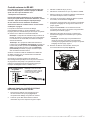
External Control
The pump can be externally controlled via digital inputs
using the Digital Input Wiring Kit (P/N 353129Z - Almond)
the RS-485 Automation Wiring Kit (P/N 356324Z -
Black). See External Control via Digital Inputs, page
6 or External Control via RS-485, page 5.
When connected to external controls, the pump will
prioritize commands as follows:
RS-485 > Digital Inputs > Drive Programmed Schedules
Refer to your control system manual for further details
on how to connect and program your pump with your
control system.
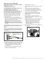
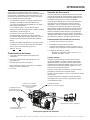
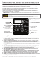
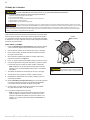
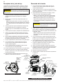
Union Kit
(Suction and Discharge Fittings)
Keypad Cover
(Buttons and LEDs Beneath)
Wiring Compartment
for Incoming Power
COM port for connection
to control system or
4-20mA owmeter
Pump Overview
2x Ferrite to be
applied on power
supply cable

WHISPERFLOXF® VS and MAX-E-PROXF® VS Commercial Variable Speed Pump Installation and User’s Guide
2
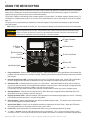
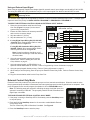
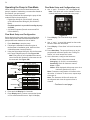
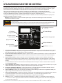
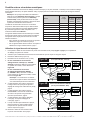
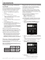
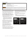
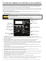
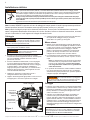
USING THE DRIVE KEYPAD
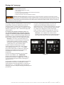
1. Program Buttons - Used to select a desired program. When the LED above a Program Button is illuminated that
program has been selected or is currently running. A blinking LED indicates that an External Control has activated
that program.
2. External Control Only LED - Indicates whether the pump is in External Control mode. When LED is illuminated
the drive-programmed schedules are disabled and only commands from digital inputs will be acted upon.
3. Start/Stop LED - Indicates whether the pump is in a “Start State”. When illuminated the pump can be started at
any time by external controls, drive-programmed schedules or manual inputs. When the pump is stopped and the
LED is not illuminated, the pump is unable to run from any type of input.
Functionality may vary based on other active features such as external control only mode or keypad lockout.
4. Start/Stop Button - Used to start and stop the pump. When the pump is stopped and the Start/Stop LED is not
illuminated, the pump is unable to run from any input.
5. Display Parameter LEDs - When illuminated, LED indicates the information being displayed on screen. A blinking
LED indicates that the parameter is currently being edited.
6. Display Button - Used to toggle between the dierent available display modes. This button is also used to set the
clock, screen brightness and pump address.
7. Quick Clean Button - Used to run the speed and duration programmed for Quick Clean. When the LED above
the Quick Clean Button is illuminated a Quick Clean cycle is active.
8. Power LED - When illuminated, LED indicates that there is live power being supplied to the pump.
9. “+” and “-” Arrows - Used to make adjustments to the pump settings. The “+” arrow increases a value, while “-”
decreases a value. Pressing and holding either arrow button will increase or decrease incremental changes faster.
(1) Program
Buttons
(2) External Control
Only LED
(4) Start/Stop Button
(8) Power LED
(5) Display Parameter
LEDs
(6) Display Button
(7) Quick Clean Button
(9) “+” and “-” Arrows
(3) Start/Stop LED
Before operating the pump for the rst time, the pump’s internal clock and operational schedules must be programmed.
Please refer to Setting the Clock and Pump Address and Programming Custom Schedules, page 8, for instructions
regarding the programming of this pump for scheduled operation.
This pump is capable of maintaining either constant speeds or constant ows. The default setting is Speed Control. For
information on conguring the pump for Flow Control via 4-20mA owmeter, refer to Operating the Pump in Flow Mode,
page 14.
The pump can be programmed and controlled from the drive keypad. Pump features and settings are also accessed
using this keypad.
Note: Always close the keypad cover after use. This will prevent damage to the keypad and other drive components.
Only press keypad buttons with your ngers. Using screwdrivers, pens or other tools to program the pump will damage the keypad.
If power is connected to the pump motor, pressing any of the following buttons referred to in this section could result in the motor
starting. Failure to recognize this could result in personal injury or damage to equipment.

WHISPERFLOXF® VS and MAX-E-PROXF® VS Commercial Variable Speed Pump Installation and User’s Guide
3
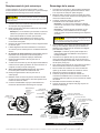
Only a qualied plumbing professional should install the WhisperFloXF® VS and Max-E-ProXF® VS Commercial
Variable Speed Pumps. Refer to “Important Safety Instructions” on pages i - ii for additional installation and safety
information.
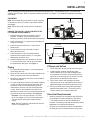
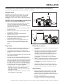
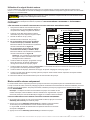
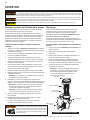
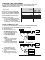
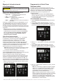
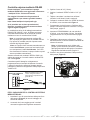
INSTALLATION
5 x SUCTION
PIPE DIAMETER
ELBOW
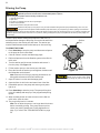
Figure 2
Location
Note: Do not install this pump within an outer enclosure
or beneath the skirt of a hot tub or spa unless marked
accordingly.
Note: Ensure the pump is secured to the equipment
pad.
ENSURE THE INSTALL LOCATION MEETS THE
FOLLOWING REQUIREMENTS:
1. Install the pump as close to the pool or spa as
possible. To reduce friction loss and improve
eciency, use short, direct suction and return piping.
2. Install a minimum of 1.5 meters from the inside wall
of the pool and spa.
3. Install the pump a minimum of 1 meter from a
heater outlet.
4. Do not install the pump more than 3 meters
above the water level.
5. Install the pump in a well ventilated location
protected from excess moisture (i.e. rain gutter
downspouts, sprinklers, etc.).
6. Install the pump with a rear clearance of at least
7.5 cm so that the motor can be removed easily
for maintenance and repair. See Figure 1.
Piping
1. For improved pool plumbing, it is recommended to
use a larger pipe size.
2. Piping on the suction side of the pump should be the
same or larger than the return line diameter.
3. Plumbing on the suction side of the pump should be
as short as possible.
4. For most installations Pentair recommends installing
a valve on both the pump suction and return lines
so that the pump can be isolated during routine
maintenance. However, we also recommend that
a valve, elbow or tee installed in the suction line
should be no closer to the front of the pump than ve
(5) times the suction line diameter. See Figure 2.
Example: A 2.5 inch pipe requires a 12.5 inch
(31.8 cm) straight run in front of the suction port.
This will help the pump prime faster and last
longer.
Note: DO NOT install 90° elbows directly into the
suction or discharge ports.
Fittings and Valves
1. Do not install 90° elbows directly into suction port.
2. Flooded suction systems should have gate
valves installed on suction and discharge pipes
for maintenance, however, the suction gate valve
should be no closer than ve (5) times the suction
pipe diameter as described in this section.
3. Use a check valve in the discharge line when
using this pump for any application where there is
signicant height to the plumbing after the pump.
4. Be sure to install check valves when plumbing in
parallel with another pump. This helps prevent
reverse rotation of the impeller and motor.
Electrical Requirements
• Install all equipment in accordance with IEC 60364
(Low-voltage electrical installations), IEC 60364-
7-702 (Requirements for special installations or
locations - Swimming pools and other basins) and all
applicable local codes and ordinances.
• A means for disconnection must be incorporated in
the xed wiring in accordance with the wiring rules.
Figure 1
6 IN. (15.2 CM)
MINIMUM
3 IN.
(7.6 CM)
MINIMUM

WHISPERFLOXF® VS and MAX-E-PROXF® VS Commercial Variable Speed Pump Installation and User’s Guide
4
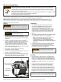
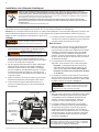
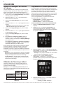
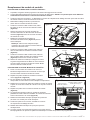
Electrical Installation
RISK OF ELECTRICAL SHOCK OR ELECTROCUTION. This pump must be installed by a licensed or certied electrician or a
qualied service professional in accordance with IEC 60364 (Low-voltage electrical installations), IEC 60364-7-702 (Requirements
for special installations or locations - Swimming pools and other basins) and all applicable local codes and ordinances. Improper
installation will create an electrical hazard which could result in death or serious injury to users, installers, or others due to electrical
shock, and may also cause damage to property.
Always disconnect power to the pump at the circuit breaker before servicing the pump. Failure to do so could result in death
or serious injury to service people, users or others due to electric shock.
Read all servicing instructions before working on the pump.
Note: ALWAYS reinstall the cover onto the eld wiring compartment when leaving the pump unsupervised. This will
prevent foreign matter (rainwater, dust, etc.) from accumulating inside the compartment.
Note: When connecting the pump to an automation system, continuous power must be supplied to the pump
by connecting it directly to the circuit breaker. When using an automation system, be sure that no other lights or
appliances are on the same circuit.
Wiring
DO NOT install this pump in conjunction with a
motor starter. Using a motor starter with this pump
can cause low voltage alarms and may cause permanent drive damage.
1. Be sure all electrical breakers and switches are
turned o before wiring motor.
STORED CHARGE - Wait at least sixty
(60) seconds before servicing.
2. Be sure that the supply voltage meets the
requirements listed on the motor nameplate. If these
requirements are not met, permanent motor damage
may occur.
3. In order to comply with EMC directive, a shielded
power supply cable, compliant with IEC 60364 (Low-
voltage electrical installations), IEC 60364-7-702
(Requirements for special installations or locations
- Swimming pools and other basins), shall be used.
The 2 ferrites provided with the pump shall be applied
on the cable close to drive-end.
4. Use a strain relief and be sure all electrical
connections are clean and tight.
5. Cut the wires to the appropriate length so they do not
overlap or touch when connected.
6. Wire the pump according to instructions given on the
inside of the eld wiring cover, then secure the eld
wiring cover with the four (4) corner screws.
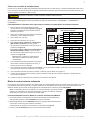
Grounding
1. Permanently ground the motor using the green
ground screw (Figure 3). Use the correct wire
size and type specied by IEC 60364 (Low-
voltage electrical installations), IEC 60364-7-702
(Requirements for special installations or locations
- Swimming pools and other basins). Be sure the
ground wire is connected to an electrical service
ground.
2. The pump should be permanently connected to either
a circuit breaker, 2-pole timer or 2-pole relay.
Note: If AC power is supplied by a RCD circuit
breaker, the pump should be wired on its
own independent circuit unless the pump is
operated in tandem with a Pentair salt chlorine
generator.
3. A surge jumper has been factory-installed between
the two (2) bottom screw terminals in the wiring
compartment. Ensure this surge jumper is in place
before wiring the pump. See Figure 3.
This surge jumper grounds all drive components
and will protect them from repeated voltage
surges. If surge jumper is not installed damage to the pump drive may
occur.
Bonding
1. Bond the motor to the structure in accordance with
IEC 60364 (Low-voltage electrical installations), IEC
60364-7-702 (Requirements for special installations
or locations - Swimming pools and other basins). Use
a solid copper bonding conductor not smaller than
2.5 mm2.
2. Connect the wire from the accessible bonding lug
on the motor to all metal parts of the swimming
pool, spa, or hot tub structure and to all electrical
equipment, metal conduit, and metal piping within 5
feet (1.5 meters) of the inside walls of the swimming
pool, spa, or hot tub. Run a wire from the external
bonding lug to the bonding structure. See Figure 3.
Note: When the pump is started and stopped by removing
power with a relay or timer, a two-pole device should be used to
apply and remove power to both POWER LINE TERMINALS.
Bonding Lug
Ground Wire
Connection
(Green Screw)
Figure 3
Factory-Installed
Surge Jumper

WHISPERFLOXF® VS and MAX-E-PROXF® VS Commercial Variable Speed Pump Installation and User’s Guide
5
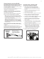
External Control via RS-485
Pentair Intellipool
®
can control the pump via RS-485
after rmware update to:
- Intellipool 5.10 or later revision
For more information on the update procedure and
to get latest rmwares, please visit:
https://www.intellipool.eu/pool/poolLogin
If you have a previous version of the rmware, refer
to External Control via Digital Inputs on page 6.
When paired with the RS-485 Automation Wiring Kit
(P/N 356324Z - Black) the pump can be externally
controlled by a control system through an RS-485
communication cable.
Note: When externally controlled via RS-485, the
pump can only operate in Speed Mode. To operate in
Flow Mode digital inputs must be used.
Note: If the pump is manually stopped using the
Start/Stop button, the pump will not run until the
Start/Stop button is pressed. If the Start/Stop LED is
illuminated, the pump is active and can be controlled
externally.
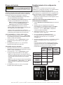
Only the GREEN and YELLOW conductors will be used
to wire the pump for external control via RS-485. See
Figure 4.
Refer to the control system manual for specic details
on connecting and programming. Control systems using
older rmware may require the pump to be designated
as “IntelliFlo VS".
YELLOW
GREEN
Automation System
COM Port
Note: Only the GREEN and
YELLOW wires will be used. All
other wires should be cut off at the
cable sheath.
From
Pump
4
3
2
1
Figure 4
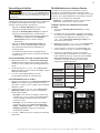
TO WIRE FOR EXTERNAL CONTROL USING RS-485:
1. Route the communication cable from the Pump
Com Port (Figure 5) to the control system wiring
compartment.
2. Ensure the cable reaches all necessary terminals
and cut to the necessary length.
3. Strip the cable 3/4" (19 mm).
4. Strip the GREEN and YELLOW conductors 1/2" (13
mm).
5. Cut back and terminate unused conductors
according to local and national electrical codes.
6. Connect YELLOW and GREEN conductors to the
control system as shown in Figure 4.
7. Program the pump's internal clock and pump
address. Refer to Setting the Clock and Pump
Address, page 8.
8. Set PROGRAM 1 to a speed of 0 RPM and
duration of 24 hours. Refer to Programming Custom
Schedules on page 8.
9. Disable priming at the pump. Priming duration and
speeds will be controlled by the control system.
Note: If priming is not disabled at the pump,
priming will continue to be controlled by
the pump’s programming. Refer to Priming
Adjustment, page 11.
10. Plug the communication cable into the pump’s Com
Port (Figure 5).
Figure 5
COM Port

WHISPERFLOXF® VS and MAX-E-PROXF® VS Commercial Variable Speed Pump Installation and User’s Guide
6
External Control via Digital Inputs
When paired with either the Digital Input Wiring Kit (P/N 353129Z - Almond) or RS-485 Automation Wiring Kit (P/N
356324Z - Black), the pump can be externally controlled by digital input signals.
Note: If the pump is manually stopped using the
Start/Stop button, the pump will not run until the
Start/Stop button is pressed. If the Start/Stop
LED is illuminated, the pump is active and can be
controlled externally.
The communication cable provided with these kits
features a watertight connection that plugs into
the Pump Com Port (Figure 5 on page 5). The
opposite end of the cable has either 6 or 8 conductors
dened in Table 1.
A trigger signal is required to externally control the
pump via digital inputs. This required output signal can
to be provided in one of the following ways:
• By the pump drive. Refer to Using the Pump’s
Output Signal.
• By an external low voltage signal. Refer to Using
an External Input Signal on page 7.
Using the Pump's Output Signal
1. Route the communication cable from the Pump Com Port (Figure 5 on page 5) to the control system wiring
compartment.
2. Ensure the cable reaches all necessary terminals and cut to the necessary length.
3. Strip the cable 3/4" (19 mm).
4. Strip all conductors 1/2" (13 mm).
5. If using Digital Input Wiring Kit (P/N
353129Z - Almond): Wire communication
cable to control system as shown in Figure
6A.
If using RS-485 Automation Wiring
Kit (P/N 356324Z - Black): Wire
communication cable to control system as
shown in Figure 6B.
Note: Unused conductors should be cut
o and terminated according to local
and national electrical codes.
6. Using the pump keypad, program the
pump's internal clock. Refer to Setting the
Clock and Pump Address on page 8.
7. Using the pump keypad, set PROGRAM 1
to 0 RPM and a duration of 24 hours. Refer
to Programming Custom Schedules on
page 8.
8. Using the pump keypad, disable priming.
Refer to Priming Adjustment on page 11.
9. When ready to start the pump, place the
pump into External Control Only mode.
Refer to External Control Only Mode on
page 7.
10. Plug the communication cable into the
Pump Com Port.
RELAY 1 RELAY 2RELAY 3RELAY 4 RELAY
LINE 1
LOAD 1
LOAD 2
LINE 2
POWER RELAY (DPST)
RED (R) OUTPUT FOR D.I. TRIGGER
GREEN (G) SPEED 1 DIGITAL INPUT
YELLOW (Y) SPEED 2 DIGITAL INPUT
ORANGE (O) SPEED 3 DIGITAL INPUT
BROWN (B) SPEED 4 DIGITAL INPUT
BLACK (K)GROUND
G
R
RRR
O
Y
B
K
RELAY 1 RELAY 2RELAY 3RELAY 4 RELAY
LINE 1
LOAD 1
LOAD 2
LINE 2
POWER RELAY (DPST)
W
R
RRR
O
Bl
B
K
RED (R) OUTPUT FOR D.I. TRIGGER
WHITE (W) SPEED 1 DIGITAL INPUT
BLUE (Bl) SPEED 2 DIGITAL INPUT
ORANGE (O) SPEED 3 DIGITAL INPUT
BROWN (B) SPEED 4 DIGITAL INPUT
BLACK (K)GROUND
GREEN (G)NOT USED
YELLOW (Y) NOT USED
Figure 6A
Figure 6B
Digital Input Wiring Kit
(P/N 353129Z - Almond)
RS-485 Automation Kit
(P/N 356324Z - Black)
Denition Signal Range
Wire Color
Wiring Kit
353129Z
Almond
Wiring Kit
356324Z
Black
+24V Output for Digital Inputs 0-20mA Red Red
RS-485 A -7V to +12V - Yellow
RS-485 B -7V to +12V - Green
PROGRAM 1 Digital Input 0, 5-30V AC/DC Green White
PROGRAM 2 Digital Input 0, 5-30V AC/DC Yellow Blue
PROGRAM 3 Digital Input 0, 5-30V AC/DC Orange Orange
QUICK CLEAN Digital Input 0, 5-30V AC/DC Brown Brown
Common Ground 0V Black Black
Table 1

WHISPERFLOXF® VS and MAX-E-PROXF® VS Commercial Variable Speed Pump Installation and User’s Guide
7
Using an External Input Signal
When using an externally supplied low voltage signal for external control, input voltage must be within 5-30V AC/DC.
The wiring kit's RED wire is only intended to carry the +24V output signal from the drive and will NOT be used.
The +24V signal (RED wire) is output from the drive only and should never be wired to another power supply. Improper wiring
will damage the drive.
The external output signal can be regulated by switches or relays to initiate a desired pump function. If multiple digital
inputs are active, the priority is: QUICK CLEAN > PROGRAM 3 > PROGRAM 2 > PROGRAM 1.
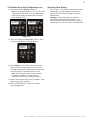
TO WIRE FOR EXTERNAL CONTROL USING AN EXTERNAL INPUT SIGNAL:
1. Route the communication cable from the Pump
Com Port (Figure 5 on page 5) to the control
system wiring compartment.
2. Ensure the cable reaches all necessary terminals
and cut to the necessary length.
3. Strip the cable 3/4" (19 mm).
4. Strip all conductors 1/2" (13 mm).
5. If using Digital Input Wiring Kit (P/N 353129Z
- Almond): Wire communication cable to control
system as shown in Figure 7A.
If using RS-485 Automation Wiring Kit (P/N
356324Z - Black): Wire communication cable to
control system as shown in Figure 7B.
Note: Unused conductors should be cut o
and terminated according to local and national
electrical codes.
6. Using the pump keypad, program the pump's
internal clock. Refer to Setting the Clock and
Pump Address on page 8.
7. Using the pump keypad, set PROGRAM 1 to a
speed of 0 RPM and duration of 24 hours. Refer to Programming Custom Schedules on page 8.
8. Using the pump keypad, disable priming. Refer to Priming Adjustment on page 11.
9. When ready to start the pump, place the pump into External Control Only mode. Refer to External Control Only
Mode.
10. Plug the communication cable into the Pump Com Port.
External Control Only Mode
External Control Only mode will only allow the pump to run from external controls/inputs. When this mode is active
the programmed pump schedule is deactivated, and user speed requests from the keypad will not be accepted. If the
pump is stopped a user can still program the speeds for all four PROGRAM buttons.
Note: The following steps are required if controlling the pump via digital inputs, but
optional if controlling via RS-485. The pump will prioritize RS-485 commands over
digital input commands.
TO ENABLE/DISABLE EXTERNAL CONTROL ONLY MODE:
1. If the pump is running or Start/Stop LED is illuminated, press the Start/Stop button
to stop the pump.
2. Press and hold the Start/Stop button for 10 seconds to enable/disable External
Control Only mode.
The Ext. Control Only LED will illuminate if enabled. See Figure 8.
3. Press the Start/Stop button to start the pump.
9:00
Pm
Figure 8
RED
GREEN SPEED 1 DIGITAL INPUT
YELLOW SPEED 2 DIGITAL INPUT
ORANGE SPEED 3 DIGITAL INPUT
BROWN QUICK CLEAN DIGITAL INPUT
BLACK GROUND
EXTERNAL
LOW VOLTAGE
SUPPLY
(5-30V AC/DC)
DO NOT USE
WHITE SPEED 1 DIGITAL INPUT
BLUE SPEED 2 DIGITAL INPUT
ORANGE SPEED 3 DIGITAL INPUT
BROWN QUICK CLEAN DIGITAL INPUT
BLACK GROUND
EXTERNAL
LOW VOLTAGE
SUPPLY
(5-30V AC/DC)
DO NOT USE
YELLOWNOT USED
GREEN NOT USED
RED
Figure 7A
Figure 7B
RS-485 Automation Kit
(P/N 356324Z - Black)
Digital Input Wiring Kit
(P/N 353129Z - Almond)

WHISPERFLOXF® VS and MAX-E-PROXF® VS Commercial Variable Speed Pump Installation and User’s Guide
8
OPERATION
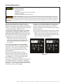
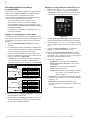
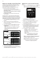
Setting the Clock and Pump Address
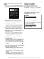
When power is rst connected to the pump the clock
will blink to indicate that is has not been set. Custom
schedules are based on this clock setting, so the clock
must be set rst.
1. Press and hold Display for 3 seconds.
2. Use “+” and “-” to choose between a 12 or 24 hour
time format.
3. Press Display to advance.
4. Use “+” and “-” to program the current time.
Note: In the 12 hour time format AM/PM will
display in the bottom right corner.
5. Press Display to advance.
6. Use “+” and “-” to adjust the screen backlight
brightness.
7. Press Display to advance.
8. If controlling pump via RS-485: Use “+” and “-”
to assign one of four pump addresses, then press
Display to exit the menu.
If controlling the pump via digital inputs or from
the drive: Press Display twice to exit the menu.
During a power outage, the drive will retain the clock
setting for as long as 24 hours. If the power is out longer
than 24 hours, the clock will have to be reset. If the drive
has lost the user set time, the clock will continuously
blink until the time is reset.
Note: When power is returned to the pump after
a prolonged outage (24+ hours) the clock will
automatically set itself to the PROGRAM 1 start
time, blink and advance. The pump will also run the
associated schedule from that start time.
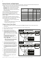
Using the Default Schedule
The default schedule is designed to provide ltration for
a typical pool. See Table 2 for default schedule.
Note: The Start/Stop button must be pressed, and the
Start/Stop LED illuminated, for the pump to run.
Duration
(Hours)
Speed
(RPM)
PROGRAM 1 24 1720
PROGRAM 2 0 2500
PROGRAM 3 0 3000
Table 2
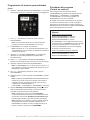
Programming Custom Schedules
To customize your pump’s schedule, the pump must
be stopped. Ensure that the Start/Stop LED is not
illuminated.
The clock must be set before programming a custom
schedule, unless externally controlling the pump through
digital inputs. When controlling the pump by digital
inputs, schedules will be based on the automation
system’s clock.
When programming, the LED next to the parameter you
are editing will blink.
“Spd” - Run Speed
“Time” - Start Time
“Duration” - Run Time
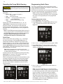
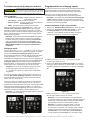
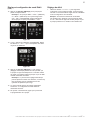
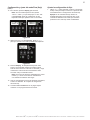
TO PROGRAM A CUSTOM SCHEDULE:
1. Press Start/Stop to stop the pump.
2. Press “1”. The PROGRAM 1 LED and “Speed/FL%”
parameter LED will blink while editing. See Figure 9.
3000
Figure 9
3. Use “+” and “-” to adjust the PROGRAM 1 speed in
RPM, or percentage of ow if operating in Flow Mode.
Note: If operating the pump with external controls,
set PROGRAM 1 speed to 0 RPM.
4. Press “1”. The PROGRAM 1 start time will display.
The “Time” parameter LED will begin to blink. See
Figure 10.
8:00am
Figure 10
5. Use “+” and “-” to adjust the PROGRAM 1 start time.
- Continue to next page -

WHISPERFLOXF® VS and MAX-E-PROXF® VS Commercial Variable Speed Pump Installation and User’s Guide
9
Programming Custom Schedules (cont.)
6. Press “1”. PROGRAM 1 duration will display. The
“Duration” parameter LED will begin to blink. See
Figure 11.
2:00
Figure 11
7. Use “+” and “-” to adjust the PROGRAM 1 duration in
hours and minutes.
Note: If operating the pump with external controls,
program PROGRAM 1 duration to 24 hours.
8. PROGRAM 1 has been successfully programmed.
Note: Pressing “1” will continue to cycle through these
parameters, but changes are immediately saved as
they are adjusted.
9. Press “2”. The PROGRAM 2 LED and “Speed/FL%”
parameter LED will blink while editing.
10. Use “+” and “-” to adjust the PROGRAM 2 speed in
RPM, or percentage of ow if operating in Flow Mode.
11. Press “2”. The PROGRAM 2 duration will display.
Note: PROGRAM 2 and 3 do not have a start time, as
they begin their duration after the previous PROGRAM
1 nishes.
12. Use “+” and “-” to adjust the PROGRAM 2 duration in
hours and minutes.
13. Repeat steps 9-12 to program PROGRAM 3 and QUICK
CLEAN.
Note: The PROGRAM 3 duration will be limited to the
remaining time in a 24 hour day. Any time in the 24
hour day not programmed into PROGRAM 1-3, the
pump will not run.
[ PROGRAM 1 + PROGRAM 2 + PROGRAM 3 < 24 Hours ]
14. Press Start/Stop and ensure the Start/Stop LED is
illuminated. The pump is now active and will run the
custom schedule.
Note: If the pump has been stopped via the Start/
Stop button, the pump will not run until the Start/
Stop button is pressed again. If the Start/Stop LED
is illuminated, the pump is active and will run the
programmed schedule.
Note: If you do not want the pump to run during a
specic time of the day, any of the PROGRAM can be
programmed to 0 RPM. This ensures the pump will
not run during the PROGRAM duration.
Program Priorities
(Non-External Control)
For schedule duration settings, PROGRAMs are
prioritized as follows: PROGRAM 1 -> PROGRAM
2 -> PROGRAM 3. PROGRAM 1 is the highest
priority, while PROGRAM 3 is the lowest.
The drive will not allow programming a schedule of
more than 24 hours. When the 24th hour of duration
is programmed, time will be taken from the lower
priority PROGRAM and added to the PROGRAM
being adjusted.
Example:
Starting Schedule (Before Adjustment)
PROGRAM 1 duration = 20 hours
PROGRAM 2 duration = 2 hours
PROGRAM 3 duration = 2 hours
If PROGRAM 1 is set to run for 23 hours,
PROGRAM 2 (lower priority) will automatically
adjust to a 1 hour duration and PROGRAM 3
(lowest priority) will adjust to a 0 hour duration.
End Schedule (After Adjustment)
PROGRAM 1 duration = 23 hours
PROGRAM 2 duration = 1 hour
PROGRAM 3 duration = 0 hours

WHISPERFLOXF® VS and MAX-E-PROXF® VS Commercial Variable Speed Pump Installation and User’s Guide
10
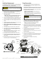
Prime the pump before starting the pump for the rst time. To
avoid permanent damage to the pump, remove the lid and ll the
strained pot up to the suction port with water. The strainer pot
must be lled with water before initial start-up or after servicing.
TO PRIME THE PUMP:
1. Press Start/Stop to stop the pump and disconnect all power
to the pump at the circuit breaker.
2. Close all valves in suction and discharge pipes.
3. Relieve all pressure from the ltration system at the lter air
relief valve.
4. Turn the strainer pot lid counter-clockwise and remove it
from the pump. See Figure 12.
5. Fill the strainer pot up to the suction port with water.
6. Place the lid onto the strainer pot and tighten clockwise until
the lid handles are horizontal.
Note: Ensure the lid O-ring is properly placed and is not
being pinched between the lid and strainer pot.
7. Open all valves in suction and discharge pipes.
8. Open the lter air relief valve and stand clear of the lter.
9. Reestablish power to the pump and ensure green power
light is on.
10. Press Start/Stop to start the pump. The pump will begin to
prime (if enabled) and ramp up to the programmed priming
speed.
11. When a steady stream of water comes out of the lter air
relief valve, close the valve.
12. The pump will prime for 5 minutes.
Note: Do not allow the pump to run longer than 30 minutes
before succesfully priming. If the pump does not prime,
check your priming speed (see Priming Adjustment on
page 11) or refer to the TROUBLESHOOTING on page
20.
Priming the Pump
This pump is shipped with Priming mode ENABLED. Unless the Priming Speed has been modied, the pump will ramp up to 3450
RPM when powered on for the rst time, and the Start/Stop button is pressed.
Before turning the pump ON, be sure the following conditions are met:
1. Open lter air relief valve.
2. Open valves.
3. Pool return is completely open and clear of any blockages.
4. Water in the pump basket.
5. Stand clear of the lter or other pressurized vessels.
DO NOT run the pump dry. If the pump is run dry, the shaft seal will be damaged and the pump will start leaking. If this occurs, the
damaged seal must be replaced. ALWAYS maintain proper water level in your pool (half way up skimmer opening). If the water level
falls below the skimmer opening, the pump will draw air through the skimmer, losing the prime and causing the pump to run dry, resulting in a damaged seal.
Continued operation in this manner could cause a loss of pressure, resulting in damage to the pump case, impeller and seal and may cause property and
personal injury.
Do not add chemicals to the system
directly in front of pump suction. Adding
undiluted chemicals may damage the pump and will void the
warranty.
Lid
Figure 12
Suction
Port

WHISPERFLOXF® VS and MAX-E-PROXF® VS Commercial Variable Speed Pump Installation and User’s Guide
11
Priming will automatically run when the pump is
started, except when running a Quick Clean cycle.
Default Priming Speed is 3450 RPM, and will last for 5
minutes. The drive will display and cycle through “PrI
-- Priming Speed, PrI -- Remaining Time”.
If externally controlling the pump via an RS-485
connection and priming is enabled at both the
pump and control system: Both priming timers will
start simultaneously, but pump priming settings will
take priority over the control system settings.
Note: After the pump’s priming cycle has
completed, if there is time remaining on the
control system priming timer the pump will
run the control system priming speed until the
timer expires.
During the priming sequence, priming speed
can be adjusted between 1700 and 3450 RPM
using the “+” and “-” arrows. Setting the priming
speed below 1700 RPM, will disable priming
and the pump will immediately begin to run the
scheduled speed.
When priming is disabled and the pump is
started, the screen will display, “PrI -- 0FF” for
10 seconds while running the scheduled speed
(see Figure 13). This 10 second delay allows
time to enable priming by pressing “+”.
If priming is re-enabled, the pump will transition from
the scheduled speed to 1700 RPM. If necessary,
priming speed can then be increased 1700 RPM by
pressing “+”. The 5 minute priming countdown timer
starts when priming is rst engaged.
Priming Adjustment
This pump is shipped with Priming ENABLED. The pump will ramp up to 3450 RPM when the pump is initially started.
Before turning the pump ON:
1. Open lter air relief valve.
2. Open valves.
3. Pool return is completely open and clear of any blockages.
4. Water in the pump basket.
5. Stand clear of the lter or other pressurized vessels.
DO NOT run the pump dry. If the pump is run dry, the shaft seal will be damaged and the pump will start leaking. If this occurs, the
damaged seal must be replaced. ALWAYS maintain proper water level in your pool (half way up skimmer opening). If the water level
falls below the skimmer opening, the pump will draw air through the skimmer, losing the prime and causing the pump to run dry, resulting in a damaged seal.
Continued operation in this manner could cause a loss of pressure, resulting in damage to the pump case, impeller and seal and may cause property and
personal injury.
Priming time can change based on local environmental
conditions such as water temperature, atmospheric
pressure, and your pool’s water level. All of these
things should be taken into consideration when setting
the priming speed.
Test and verify priming speeds more than once, letting
the water drain from the system in between each test.
Note: To prevent air from entering the system, the
pump strainer pot should always be lled with water
up to the bottom of the suction port.
Figure 13
Pr1 0FF

WHISPERFLOXF® VS and MAX-E-PROXF® VS Commercial Variable Speed Pump Installation and User’s Guide
12
If power is connected to the pump, pressing any of the
following buttons referred to in this section could result
in the motor starting. Failure to recognize this could result in personal injury or
damage to equipment.
Programming Quick Clean
The pump is equipped with a Quick Clean feature, which
can be engaged to temporarily run at higher or lower speeds
ranging from 300 to 3450 RPM.
At the end of a Quick Clean cycle, the pump will automatically
return to the appropriate point in its programmed schedule.
Note: Pressing and holding Quick Clean for more than
3 seconds will cancel a Quick Clean cycle. The pump will
then return to the appropriate point in its programmed
schedule.
TO PROGRAM QUICK CLEAN:
1. Press Start/Stop to stop the pump.
2. Press Quick Clean. The Quick Clean LED and “Spd
/ %FL” parameter LED will blink while editing. See
Figure 15.
3450
Figure 15
3. Use “+” and “-” to adjust the Quick Clean speed in RPM.
4. Press Quick Clean. The Quick Clean duration will
display. The “Duration” parameter LED will blink while
editing. See Figure 16.
2:00
Figure 16
5. Use “+” and “-” to adjust the Quick Clean duration in
hours and minutes.
Note: It is recommended that you do not set the Quick
Clean duration to 0 HRS. Setting the Quick Clean duration
to 0 HRS will prevent edits to the duration setting while the
motor is running. The motor will need to be stopped.
Note: Quick Clean duration does not aect the start or
stop times of the 24-hour schedule. For example, if Quick
Clean runs during a period overlapping with a later part of
PROGRAM 1 and an early part of PROGRAM 2, the start
time of PROGRAM 3 is not aected.
Operating the Pump While Running
Pressing the Display button will cycle through the current
parameters:
• Speed / %FL — current run speed or
percent ow
• Time — current time of day
• Duration — amount of time remaining at the
current PROGRAM
• Watts — amount of watts currently being
consumed
Pressing any of the PROGRAM Buttons (“1”, “2”, “3”,
“Quick Clean”) while the pump is running will act as a
temporary override. The pump will run the speed and
duration programmed for that button. Once completed the
pump will return to the appropriate point in the programmed
schedule.
Note: If PROGRAM speeds are adjusted while the pump is
running, the pump will run the entered speed for the rest of
the PROGRAM duration, but will not save the adjustments.
Exception: QUICK CLEAN Speed and Duration
adjustments will always be immediately saved.
Quick Clean
During a Quick Clean cycle, pressing “+” or “-” will change
the speed accordingly. Pressing Quick Clean within 10
seconds after will allow for adjustment of the Quick Clean
duration using the “+” and “-” arrows. These changes will be
saved immediately and are the new settings for Quick Clean.
Pressing Quick Clean again will cycle through the two Quick
Clean settings. The pump will exit editing mode if no buttons
are pressed within 10 seconds.
Note: While in keypad lockout mode the quick clean
feature is enabled and the “+” and “-” buttons can be used
to make temporary changes.
A Quick Clean cycle can be stopped by pressing and holding
Quick Clean for 3 seconds. The pump will return to the
appropriate point in its 24-hour schedule.
When a connected control system is in Service Mode, a pump
connected via RS-485 can still run its Quick Clean program.
Once Service Mode is enabled the pump display will flash
between “SEr” and the current Quick Clean speed (Figure
14). Once Service Mode is disabled the pump will resume
normal operation.
Note: Quick Clean speed will read 0 when Quick Clean is off.
Figure 14

WHISPERFLOXF® VS and MAX-E-PROXF® VS Commercial Variable Speed Pump Installation and User’s Guide
13
Keypad Lockout
Keypad lockout will not prevent the motor from
being stopped by pressing the Start/Stop button. If
the pump is stopped with the Start/Stop button during Keypad Lockout, it
can not be restarted until the keypad is unlocked.
The pump features a Keypad Lockout mode. Keypad
Lockout is intended to prevent unwanted changes to
pump settings. When locked, the pump will only respond
to:
• Pressing Display to cycle through current pump
information.
• Pressing Start/Stop to stop the pump and/or
enable/disable external control.
Note: The pump can not be manually restarted
using the Start/Stop button until the keypad is
unlocked.
• Pressing Quick Clean to start a quick clean cycle
or making temporary adjustments to quick clean
settings.
• Any drive-programmed or external control
schedules, as long as the Start/Stop LED is
illuminated.
TO PROGRAM A LOCKOUT CODE:
1. Press and hold “1” and Quick Clean simultaneously
for 3 seconds. “EntEr Loc CodE” will scroll across
the screen.
2. Use the “1”, “2”, “3” and Quick Clean buttons, enter
your desired four-digit keypad lockout code.
3. “Loc on” will scroll across the screen. Keypad
Lockout is now active.
TO UNLOCK THE PUMP:
1. Press and hold the “1” and Quick Clean buttons
for atleast 3 seconds. “Enter Loc Code” will scroll
across the screen.
2. Use the “1”, “2”, “3” and Quick Clean buttons to
enter your four-digit keypad lockout code.
Note: If the lockout code is entered incorrectly,
“Loc Err” will scroll across the screen. Repeat the
steps above to reenter your code.
Note: If your custom lockout code is forgotten,
press Quick Clean -> Quick Clean -> “2” ->
Quick Clean to erase the existing code and
unlock the keypad.
3. “Loc oFF” will scroll across the screen. The keypad
is now unlocked.
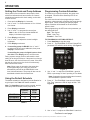
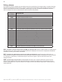
Factory Reset
The drive can be reset to factory settings if necessary.
A Factory Reset will remove all programmed settings
and schedules, except for the clock. Be sure a factory
reset is necessary before performing a Factory Reset,
as the results are immediate.
Note: A Factory Reset can not be performed when
in Keypad Lockout mode.
TO PERFORM A FACTORY RESET:
1. Press Start/Stop to stop the pump.
2. Record all of the custom schedule settings and
the priming speed in Table 3. These settings
can be found by pressing the “1”, “2”, “3”, and
“Quick Clean” buttons and cycling through all the
screens.
3. Press and hold “1”, “2”, “3”, and “Quick Clean” for
3 seconds.
4. The screen will display “FAct rSt” if factory reset is
successful. See Figure 17.
5. Be sure to reprogram the schedule and priming
speed after the factory reset.
The pump must be turned back on with the Start/
Stop button before it will run again. The pump will
run the programmed schedule upon initial start-up.
Speed / Flow
(RPM / %)
Duration
(Hours)
Start Time
(Time Clock)
PROGRAM 1
PROGRAM 2
PROGRAM 3
QUICK
CLEAN
PRIMING
SPEED
Table 3
Figure 17
FACt r5t

WHISPERFLOXF® VS and MAX-E-PROXF® VS Commercial Variable Speed Pump Installation and User’s Guide
14
Operating the Pump in Flow Mode
When connected to an inline 4-20mA owmeter, this
pump is capable of maintaining a constant ow based on
the needs of your pool system.
Connecting a owmeter and operating the pump in ow
mode will require the purchase of:
• Digital Input Wiring Kit (P/N 353129Z - Almond)
or RS-485 Automation Wiring Kit (P/N 356324Z -
Black).
Flow mode operation is not possible if controlling the pump
via RS-485.
• A 4-20mA Flowmeter (Pentair recommends P/N
97014-4203KIT)
Flow Mode Setup and Conguration
Before beginning ow mode setup and conguration,
ensure the pool lter has been backwashed and all
pump and skimmer baskets are free of debris.
1. Press Start/Stop to stop the pump.
2. Following the installation instructions given in
the owmeter’s installation guide, install an inline
4-20mA owmeter into the plumbing.
3. Using the Digital Input Wiring Kit, wire the owmeter
to the pump’s digital input port. See Figure 18A.
Note: Flow mode is not compatible with external
control via RS-485. However, a owmeter can still
be connected. See Figure 18B.
RED
GREEN SPEED 1 DIGITAL INPUT
YELLOW SPEED 2 DIGITAL INPUT
ORANGE SPEED 3 DIGITAL INPUT
BROWN QUICK CLEAN DIGITAL INPUT
BLACK GROUND
+24V OUTPUT FOR D.I. TRIGGER
FLOWMETER
DIGITAL INPUTS
WHITE SPEED 1 DIGITAL INPUT
BLUE SPEED 2 DIGITAL INPUT
ORANGE SPEED 3 DIGITAL INPUT
BROWN QUICK CLEAN DIGITAL INPUT
BLACK GROUND
YELLOWNOT USED
GREEN NOT USED
RED +24V OUTPUT FOR D.I. TRIGGER
FLOWMETER
DIGITAL INPUTS
Digital Input Wiring Kit
(P/N 353129Z - Almond)
RS-485 Automation Kit
(P/N 356324Z - Black)
Figure 18A
Figure 18B
4. Press and hold Display for 3 seconds.
5. Press Display three (3) times to access the Speed
or Flow mode selection screen. “Spd” will display.
Flow Mode Setup and Conguration (cont.)
6. Use “+” and “-” to scroll to “Flo”. See Figure 19.
Note: This option will not be available unless a
4-20mA owmeter is connected to the pump.
7. Press Display. The Flow Mode High Speed
screen.
8. Use “+” and “-” to set a high speed for ow mode
between 2000 and 3450 RPM.
9. Press Display. “Press Start” will scroll across the
screen.
10. Press Start/Stop. The pump will ramp up to the
programmed maximum speed, then “Cong Flo
Sensor” will scroll across the screen.
11. At the owmeter, congure the owmeter:
K Factor: Refer to owmeter manual
Averaging: 10-30 (20 is recommended)
Sensitivity: Refer to owmeter manual
4-Set: 0 GPM
20-Set: GPM displayed while pump motor is at
maximum speed set in step 8.
Note: Flowmeter conguration will timeout at the
drive after 10 minutes. If this occurs, repeat steps
4 through 10.
Note: The owmeter 20-Set will need to be
recongured each time the system’s lter is
cleaned.
- Continue to next page -
FLo
Figure 19

WHISPERFLOXF® VS and MAX-E-PROXF® VS Commercial Variable Speed Pump Installation and User’s Guide
15
Flow Mode Setup and Conguration (cont.)
12. At the pump, press Display to advance.
Note: If the pump displays “LoFlo” or “HiFlo” and
a percentage other than “100” (see Figure 20),
adjust 20-set setting at the owmeter until the
pump displays “100”.
13. “Aver” will display (see Figure 21). Use “+” and “-”
to match the owmeter’s averaging value.
14. Press Display. “Auto Tuning” will scroll across
the screen as the pump auto tunes. The motor
will drop to half speed and then slowly ramp down
until the minimum controllable ow is found.
Note: Auto Tuning process will take several
minutes to complete, or much longer in
installations with longer plumbing systems.
15. Motor will stop when Auto Tuning completes. Flow
Mode setup is now complete.
16. Refer to OPERATION on page 8 to continue
pump programming.
AVEr
Figure 21
Adjusting Flow Setting
1. Use “+” and “-” to increase or decrease the Flow
Percentage. This percentage is based on the
high speed set during Flow Mode setup and
conguration.
Example: If ow mode maximum speed is
3000 RPM, lowering ow percentage to “50”
will decrease the motor RPMs until the pump is
producing 50% of the ow created at 3000 RPM.
LoFL
Figure 20
88.3

WHISPERFLOXF® VS and MAX-E-PROXF® VS Commercial Variable Speed Pump Installation and User’s Guide
16
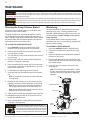
MAINTENANCE
Cleaning the Pump Strainer Basket
The strainer pot is located at the front of the pump and
houses the pump strainer basket.
The strainer basket can be viewed through the strainer
pot lid and should be visually inspected at least once a
week. Regularly emptying and cleaning the strainer basket
will lead to higher lter and heater eciency and prevent
unnecessary stress on the pump motor.
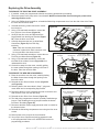
TO CLEAN THE STRAINER BASKET:
1. Press Start/Stop to stop the pump and shut o all
electrical power to the pump at the circuit breaker.
2. Open the lter air relief valve and relieve all pressure
from the ltration system.
3. Turn the strainer pot lid counter-clockwise and remove it
from the pump.
4. Remove debris and rinse out the basket. Replace the
basket if it is cracked or damaged.
5. Place the basket into the strainer pot. Ensure the notch
in the bottom of the basket is aligned with the rib in the
bottom of the strainer pot.
6. Fill the strainer pot with water up to the inlet port.
7. Clean the lid O-ring and sealing surface of the strainer
pot.
Note: It is important to keep the lid O-ring clean and
well lubricated.
8. Reinstall the lid by placing it onto the strainer pot and
tightening clockwise until the lid handles are horizontal.
Note: Ensure the lid O-ring is properly placed and is
not being pinched between the lid and strainer pot.
Note: Ensure that the side of the lid marked “Front” is
positioned at the front of the pump.
9. Open the lter air relief valve and stand clear of the lter.
10. Reestablish electrical power to the pump at the circuit
breaker and start the pump.
11. When a steady stream of water ows from the lter air
relief valve, close the valve.
THIS SYSTEM OPERATES UNDER HIGH PRESSURE. When
any part of the circulating system is serviced, air can enter the
system and become pressurized. Pressurized air can cause the
lid to separate which can result in serious injury, death, or property
damage. To avoid this potential hazard, follow above instructions.
Winterizing
You are responsible for determining when freezing
conditions may occur. If freezing conditions are
expected, take the following steps to reduce the risk
of freeze damage. Freeze damage is not covered
under warranty.
In mild climate areas, when temporary freezing
conditions may occur, run your ltering equipment all
night to prevent freezing.
TO PREVENT FREEZE DAMAGE:
1. Press the Start/Stop button to stop the pump.
2. Disconnect all power to the pump at the circuit
breaker.
3. Relieve all pressure from the ltration system at
the lter air relief valve.
4. Remove both drain plugs from the bottom of the
strainer pot and drain the pump. Store the plugs in
the strainer basket.
5. Cover the motor to protect it from severe rain,
snow and ice.
Note: Do not wrap motor with plastic or other
air tight materials during winter storage. Never
cover the motor when operating or expecting
operation.
DO NOT open the strainer pot if pump fails to prime or if pump has been operating without water in the strainer pot. Pumps operated in
these circumstances may experience a build up of vapor pressure and may contain scalding hot water. Opening the pump may cause
serious personal injury. In order to avoid the possibility of personal injury, make sure the suction and discharge valves are open and strainer pot temperature
is cool to touch, then open with extreme caution.
Always disconnect power to the pump at the circuit breaker and disconnect the digital input cable before servicing the pump. Failure to do so could
result in death or serious injury to service people, users or others due to electric shock. Read all servicing instructions before working on the pump.
To prevent damage to the pump and for proper operation of the system, clean pump strainer and skimmer baskets regularly.
Strainer Pot Assembly
Lid O-ring
Strainer Basket
Drain
Plugs
Lid
Inlet
Port
Seite wird geladen ...
Seite wird geladen ...
Seite wird geladen ...
Seite wird geladen ...
Seite wird geladen ...
Seite wird geladen ...
Seite wird geladen ...
Seite wird geladen ...
Seite wird geladen ...
Seite wird geladen ...
Seite wird geladen ...
Seite wird geladen ...
Seite wird geladen ...
Seite wird geladen ...
Seite wird geladen ...
Seite wird geladen ...
Seite wird geladen ...
Seite wird geladen ...
Seite wird geladen ...
Seite wird geladen ...
Seite wird geladen ...
Seite wird geladen ...
Seite wird geladen ...
Seite wird geladen ...
Seite wird geladen ...
Seite wird geladen ...
Seite wird geladen ...
Seite wird geladen ...
Seite wird geladen ...
Seite wird geladen ...
Seite wird geladen ...
Seite wird geladen ...
Seite wird geladen ...
Seite wird geladen ...
Seite wird geladen ...
Seite wird geladen ...
Seite wird geladen ...
Seite wird geladen ...
Seite wird geladen ...
Seite wird geladen ...
Seite wird geladen ...
Seite wird geladen ...
Seite wird geladen ...
Seite wird geladen ...
Seite wird geladen ...
Seite wird geladen ...
Seite wird geladen ...
Seite wird geladen ...
Seite wird geladen ...
Seite wird geladen ...
Seite wird geladen ...
Seite wird geladen ...
Seite wird geladen ...
Seite wird geladen ...
Seite wird geladen ...
Seite wird geladen ...
Seite wird geladen ...
Seite wird geladen ...
Seite wird geladen ...
Seite wird geladen ...
Seite wird geladen ...
Seite wird geladen ...
Seite wird geladen ...
Seite wird geladen ...
Seite wird geladen ...
Seite wird geladen ...
Seite wird geladen ...
Seite wird geladen ...
Seite wird geladen ...
Seite wird geladen ...
Seite wird geladen ...
Seite wird geladen ...
Seite wird geladen ...
Seite wird geladen ...
Seite wird geladen ...
Seite wird geladen ...
Seite wird geladen ...
Seite wird geladen ...
Seite wird geladen ...
Seite wird geladen ...
Seite wird geladen ...
Seite wird geladen ...
Seite wird geladen ...
Seite wird geladen ...
Seite wird geladen ...
Seite wird geladen ...
Seite wird geladen ...
Seite wird geladen ...
Seite wird geladen ...
Seite wird geladen ...
Seite wird geladen ...
Seite wird geladen ...
Seite wird geladen ...
Seite wird geladen ...
Seite wird geladen ...
Seite wird geladen ...
Seite wird geladen ...
Seite wird geladen ...
Seite wird geladen ...
Seite wird geladen ...
Seite wird geladen ...
Seite wird geladen ...
Seite wird geladen ...
Seite wird geladen ...
Seite wird geladen ...
Seite wird geladen ...
Seite wird geladen ...
Seite wird geladen ...
Seite wird geladen ...
Seite wird geladen ...
Seite wird geladen ...
Seite wird geladen ...
Seite wird geladen ...
Seite wird geladen ...
Seite wird geladen ...
Seite wird geladen ...
Seite wird geladen ...
Seite wird geladen ...
Seite wird geladen ...
Seite wird geladen ...
Seite wird geladen ...
Seite wird geladen ...
Seite wird geladen ...
Seite wird geladen ...
Seite wird geladen ...
Seite wird geladen ...
Seite wird geladen ...
Seite wird geladen ...
Seite wird geladen ...
Seite wird geladen ...
Seite wird geladen ...
Seite wird geladen ...
Seite wird geladen ...
Seite wird geladen ...
Seite wird geladen ...
Seite wird geladen ...
Seite wird geladen ...
Seite wird geladen ...
Seite wird geladen ...
Seite wird geladen ...
Seite wird geladen ...
Seite wird geladen ...
Seite wird geladen ...
Seite wird geladen ...
Seite wird geladen ...
Seite wird geladen ...
Seite wird geladen ...
Seite wird geladen ...
Seite wird geladen ...
Seite wird geladen ...
Seite wird geladen ...
Seite wird geladen ...
Seite wird geladen ...
Seite wird geladen ...
Seite wird geladen ...
Seite wird geladen ...
Seite wird geladen ...
Seite wird geladen ...
Seite wird geladen ...
Seite wird geladen ...
Seite wird geladen ...
Seite wird geladen ...
Seite wird geladen ...
Seite wird geladen ...
Seite wird geladen ...
Seite wird geladen ...
Seite wird geladen ...
Seite wird geladen ...
Seite wird geladen ...
Seite wird geladen ...
Seite wird geladen ...
Seite wird geladen ...
Seite wird geladen ...
Seite wird geladen ...
Seite wird geladen ...
Seite wird geladen ...
-
 1
1
-
 2
2
-
 3
3
-
 4
4
-
 5
5
-
 6
6
-
 7
7
-
 8
8
-
 9
9
-
 10
10
-
 11
11
-
 12
12
-
 13
13
-
 14
14
-
 15
15
-
 16
16
-
 17
17
-
 18
18
-
 19
19
-
 20
20
-
 21
21
-
 22
22
-
 23
23
-
 24
24
-
 25
25
-
 26
26
-
 27
27
-
 28
28
-
 29
29
-
 30
30
-
 31
31
-
 32
32
-
 33
33
-
 34
34
-
 35
35
-
 36
36
-
 37
37
-
 38
38
-
 39
39
-
 40
40
-
 41
41
-
 42
42
-
 43
43
-
 44
44
-
 45
45
-
 46
46
-
 47
47
-
 48
48
-
 49
49
-
 50
50
-
 51
51
-
 52
52
-
 53
53
-
 54
54
-
 55
55
-
 56
56
-
 57
57
-
 58
58
-
 59
59
-
 60
60
-
 61
61
-
 62
62
-
 63
63
-
 64
64
-
 65
65
-
 66
66
-
 67
67
-
 68
68
-
 69
69
-
 70
70
-
 71
71
-
 72
72
-
 73
73
-
 74
74
-
 75
75
-
 76
76
-
 77
77
-
 78
78
-
 79
79
-
 80
80
-
 81
81
-
 82
82
-
 83
83
-
 84
84
-
 85
85
-
 86
86
-
 87
87
-
 88
88
-
 89
89
-
 90
90
-
 91
91
-
 92
92
-
 93
93
-
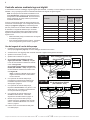 94
94
-
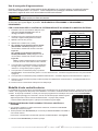 95
95
-
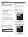 96
96
-
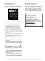 97
97
-
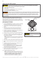 98
98
-
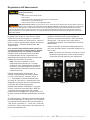 99
99
-
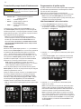 100
100
-
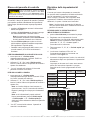 101
101
-
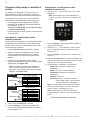 102
102
-
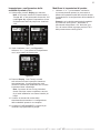 103
103
-
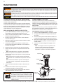 104
104
-
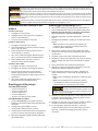 105
105
-
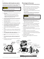 106
106
-
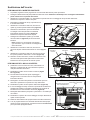 107
107
-
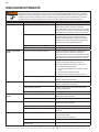 108
108
-
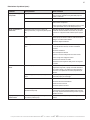 109
109
-
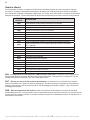 110
110
-
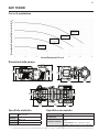 111
111
-
 112
112
-
 113
113
-
 114
114
-
 115
115
-
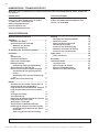 116
116
-
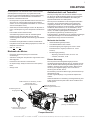 117
117
-
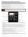 118
118
-
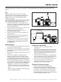 119
119
-
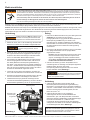 120
120
-
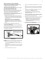 121
121
-
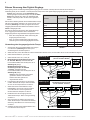 122
122
-
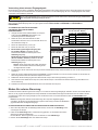 123
123
-
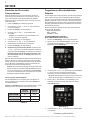 124
124
-
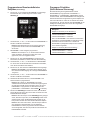 125
125
-
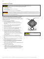 126
126
-
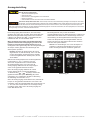 127
127
-
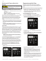 128
128
-
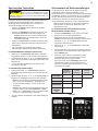 129
129
-
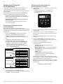 130
130
-
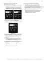 131
131
-
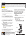 132
132
-
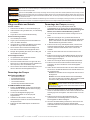 133
133
-
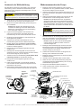 134
134
-
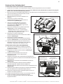 135
135
-
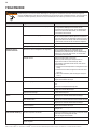 136
136
-
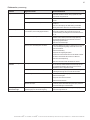 137
137
-
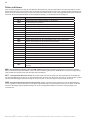 138
138
-
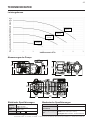 139
139
-
 140
140
-
 141
141
-
 142
142
-
 143
143
-
 144
144
-
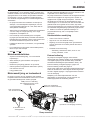 145
145
-
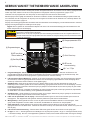 146
146
-
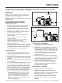 147
147
-
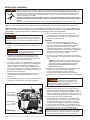 148
148
-
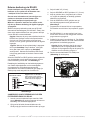 149
149
-
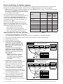 150
150
-
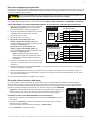 151
151
-
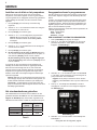 152
152
-
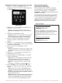 153
153
-
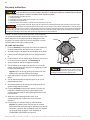 154
154
-
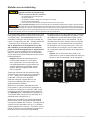 155
155
-
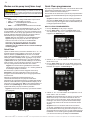 156
156
-
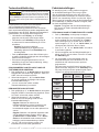 157
157
-
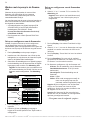 158
158
-
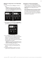 159
159
-
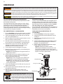 160
160
-
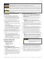 161
161
-
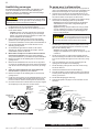 162
162
-
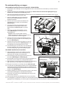 163
163
-
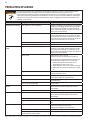 164
164
-
 165
165
-
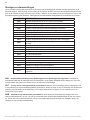 166
166
-
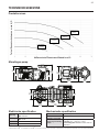 167
167
-
 168
168
-
 169
169
-
 170
170
-
 171
171
-
 172
172
-
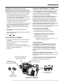 173
173
-
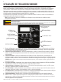 174
174
-
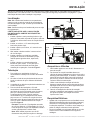 175
175
-
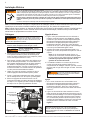 176
176
-
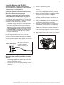 177
177
-
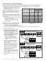 178
178
-
 179
179
-
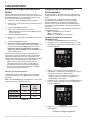 180
180
-
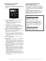 181
181
-
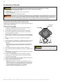 182
182
-
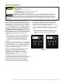 183
183
-
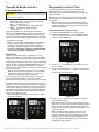 184
184
-
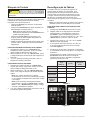 185
185
-
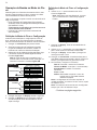 186
186
-
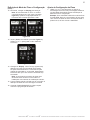 187
187
-
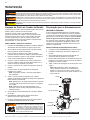 188
188
-
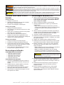 189
189
-
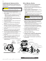 190
190
-
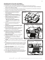 191
191
-
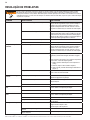 192
192
-
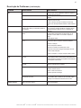 193
193
-
 194
194
-
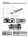 195
195
-
 196
196


in anderen Sprachen
- français: Pentair Max-E-Pro XF VS Manuel utilisateur
- español: Pentair Max-E-Pro XF VS Manual de usuario
- italiano: Pentair Max-E-Pro XF VS Manuale utente
- Nederlands: Pentair Max-E-Pro XF VS Handleiding
- português: Pentair Max-E-Pro XF VS Manual do usuário