
INFORMAZIONI TECNICHE
TECHNICAL INFORMATION
INFORMATIONS TECHNIQUES
TECHNISCHE INFORMATIONEN
INFORMACIONES TECNICAS
ART. 15302 - 15302B - 15302T
SLIP-ON
LV-12 / LV-12 BLACK
LV-12 TITANIUM
HONDA CRF 1100 L AFRICA TWIN
/ ADVENTURE SPORT / DCT
(Fits with original panniers)
TYPE: SD08; 1/1; 2/1 - SD09; 1/1; 2/1; 3/1; 4/1
26-01-22 REV.02
Omologato - Approved
Homologué - Homologado
E-Zugelassene Sportschalldämpfet

Cognome//Surname/Nom/ Name/ Apellido
Targa veicolo/Vehicle registration plate/Plaque d’immatriculation/Kennzeichen des Fahrzeuges/Matrícula del vehículo
Data e timbro del rivenditore
Date and seller’s stamp
Date et tampon du revendeur
Datum und Stempel des Verkäufers
Fecha y sello del vendedor
Tel.
Indirizzo /Address/Adresse/Adresse/ Dirección
Nome/Given name/Prénom/Vorname/ Nombre
ART. 15302 - 15302B - 15302T
8
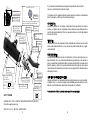
I. - Montare il blocco valvola leovince (206609) fornito in confezione con la scritta “up”
rivolta verso l’esterno (come in foto) e vincolarlo all’albero motore con la vite m3 origi-
nale. rimontare il servomotore e gli altri componenti nella posizione originale proceden-
do in ordine inverso.
GB. - Install the leovince valve canceller bracket(206609)supplied in the box with the
writing”up”facing outwards (as in the picture) and secure it to the servo motor shaft
with the original m3 screw. reassemble the servo motor and the other components in
the original position proceeding in reverse order.
F.- installer la patte bloque valve leovince (206609) fournie dans la boîte, avec l’inscrip-
tion”up”tournée vers l’extérieur (comme sur la photo) et la xer sur l’arbre du servomo-
teur avec la vis m3 d’origine. remonter le servomoteur et les autres composants dans
leur position initiale en procédant dans l’ordre inverse.
D. - installieren sie die im lieferumfang enthaltene anschlagscheibe(206609)mit dem
schriftzug “up” nach außen (wie auf dem bild) und befestigen sie sie mit der originalen
m3-schraube am servomotor. bauen sie den servomotor und die anderen komponen-
ten in umgekehrter reihenfolge wieder zusammen.
E. - instalar el bloque válvula leovince (206609) que se suministra en la caja, con la
inscripción”up”mirando hacia fuera (como se muestra en la foto) y fíjarlo en el eje del
actuador con el tornillo m3 original. volver a montar el servomotor y los demás compo-
nentes en orden inverso en su posición original.
27

3
INDICE - INDEX - INHALTSVERZEICHNIS - INDICE
Lista dei componenti/List of components
Liste des composants/Inhaltsverzeichnis
Lista de componentes pag. 4
PESO/wEIgHT/POIdS/gEwICHT pag. 5
Disegno tecnico/Technical drawing/Eclaté
Technische Zeichnung/Despiece pag. 6
Istruzioni di montaggio pag. 12
Fitting instructions pag. 14
Notice de montage pag. 16
Montageanleitungen pag. 18
Instrucciones de montaje pag. 20
KIT VALVOLA pag. 22
26
7
I - Svitare la vite e asportare la puleggia in plastica originale.
GB. - Loosen the retaining screw and remove the original plastic pulley.
F. - desserrer la vis de xation et retirer la poulie en plastique d’origine.
D. - lösen sie die verbleibende schraube und entfernen sie die ursprüngliche
kunststoff-seilrolle.
E. - aojar el tornillo de jación y quitar la polea de plástico original

4
LISTA DEI COMPONENTI - LIST OF COMPONENTS - LISTE DES
COMPOSANTS - VERPACKUNGSINHALT - LISTA DE COMPONENTES
ITALIANO
1 - Silenziatore
2 - Collettore
3 - Kit minuteria
4 - Carter paracalore
5 - Blocco valvola
ENGLISH
1 - Muffler
2 - Link pipe
3 - Fitting kit
4 - Heat shield
5 - Valve block-off
FRANCAIS
1 - Silencieux
2 - Tube de raccord
3 - Kit de fixation
4 - Cache pare-chaleur
5 - Bloque valve
DEUTSCH
1 - Endschalldämpfer
2 - Verbindungsrohr
3 - Haltesatz
4 - Hitzeschild
5 - Ventilblocks
ESPAÑOL
1 - Silenciador
2 - Tubo de conexión
3 - Kit de montaje
4 - Protector de calor
5 - Kit valvula
BLACK
cod. 3015302485
cod. 3015302201
cod. 3015302601
cod. 3015302001
cod. 206609
BLACK
cod. 3015300485
cod. 3015302201
cod. 3015302601
cod. 3015302001
cod. 206609
BLACK
cod. 3015300485
cod. 3015302201
cod. 3015302601
cod. 3015302001
cod. 206609
BLACK
cod. 3015300485
cod. 3015302201
cod. 3015302601
cod. 3015302001
cod. 206609
BLACK
cod. 3015300485
cod. 3015302201
cod. 3015302601
cod. 3015302001
cod. 206609
ACCIAIO INOX
cod. 3015302481
cod. 3015302201
cod. 3015302601
cod. 3015302001
cod. 206609
STAINLESS S.
cod. 3015302481
cod. 3015302201
cod. 3015302601
cod. 3015302001
cod. 206609
ACIER INOX
cod. 3015302481
cod. 3015302201
cod. 3015302601
cod. 3015302001
cod. 206609
EDELSTHAL
cod. 3015302481
cod. 3015302201
cod. 3015302601
cod. 3015302001
cod. 206609
ACERO INOX
cod. 3015302481
cod. 3015302201
cod. 3015302601
cod. 3015302001
cod. 206609
25
TITANIO
cod. 3015302486
cod. 3015302201
cod. 3015302601
cod. 3015302001
cod. 206609
TITANIUM
cod. 3015300486
cod. 3015302201
cod. 3015302601
cod. 3015302001
cod. 206609
TITANE
cod. 3015300486
cod. 3015302201
cod. 3015302601
cod. 3015302001
cod. 206609
TITANIUM
cod. 3015300486
cod. 3015302201
cod. 3015302601
cod. 3015302001
cod. 206609
TITANIO
cod. 3015300486
cod. 3015302201
cod. 3015302601
cod. 3015302001
cod. 206609
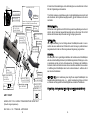
F. - retirer partiellement le servomoteur comme indiqué sur la photo, desserrer les trois
vis visibles et retirer le boîtier en plastique pour accéder aux câbles de l’actionneur.
déconnecter les deux câbles de l’actionneur et retirer le servomoteur.
D. - ziehen sie den servomotor wie in der abbildung gezeigt zum teil heraus, lösen sie
die drei sichtbaren schrauben und entfernen sie das kunststoffgehäuse, um zugang zu
den bowdenzügen zu erhalten. trennen sie die beiden bowdenzüge und entfernen sie
den servomotor.
E. - retirar parcialmente el servomotor como se muestra en la foto, quitar los tres tornil-
los visibles y retirar la tapa de plástico para acceder a los cables del actuador. desco-
nectar ambos cables del actuador y retirar el servomotor.
6
I. - Estrarre parzialmente il
servomotore come da immagi-
ne, rimuovere le tre viti a vista e
asportare il carter in plastica per
poter accedere ai cavi attuatori.
Scollegare i due cavi di aziona-
mento e rimuovere il
servomotore.
GB. - Pull the servo motor par-
tially out as shown in the picture,
loosen the three visibile screws
and remove the plastic housing
to access the actuator cables. Di-
sconnect the two actuator cables
and remove the servo motor.

5
PESO - WEIGHT - POIDS - GEWICHT (Kg)
ORIGINALE - STOCK - ORIGINE - ORIGINAL 5,96 (Kg)
Stainless steel S.s. Black Titanium
LeoVince 5,67 5,67 5,08
24
3
I. - Scollegare il connettore.
GB. - Unplug the connector.
F. - Débranchez le connecteur.
D. - Ziehen sie den stecker.
E. - Desconectar el conector.
4
I. - Rimuovere la vaschetta olio.
GB. - Remove the brake uid
reservoir.
F. - Retirer reservoir du liquide de
frein.
D. - Entfernen sie den bremsùss-
igkeitsbehalter.
E. - Retirar el depòsito de liquido
de frenos.
5
I. - Rimuovere le due viti e la clip
indicate nelle immagini.
GB. - Remove the two screws and
the clip shown in the pictures.
F. - Enlevez les deux vis et l’agrafe
montreés sur les photos.
D. - Entfernen sie die beiden
schrauben und den clip, wie auf
den bildern gezeigt.
E. - Retirar los dos tornillos y el
clip que se muestra en las fotos.

236
57
i.75
370
87
i.49,0
e.75
49
LV-12 silencer Stainless s.
Øi 75X370 RHS
Cod.
3015302481
Pipe N°1308 s.s
cod. 3015302201
Super Short spring
cod. 308574001
Aluminium spacer
ø27X8,5
Cod. 204321
Allen screw M8X25
T.C.E.I.Z.B.
Cod.200314
Strap in S.s.Ø51
Cod.300051530
Allen screw M5X12
T.B.E.I.
Cod.201031
Plain washer
5x15 Inox
Cod.406580
2x Gasket
14x4.9x1.5
Cod.200371
Mounting
plate M5 Z.B.
Cod.
204555
Plain washer
6.4x14 Inox
Cod.205833
2x Gasket
14x5.9x1.5
Cod.206367
Allen screw
M6X14 T.B.E.I.
Cod.204643
Brackets S.s
Cod.206623-206624
Carbon cover
cod. 0815302001
e
49
00007G
E
49
92R-02 0001
LV
LV12
VALVE BLOCK-OFF
Please, follow instruction supplied to fit
valve cod.206609 (thickness 8mm)
ORIGINAL
SCREW M6
136
176
Db-Killer N.66
Cod.
3015300801
Db-Killer N.67
Cod.
3015300802
ART. 15302
HONDA CRF 1100 L AFRICA TWIN/ADVENTURE SPORT/DCT
(fits with original panniers)
SLIP-ON - LV-12 - STAINLESS STEEL - APPROVED
UP 206609
DO NOT USE
ORIGINAL BUSHING
1
I. - Rimuovere il carter paracalore
dello scarico originale.
Rimuovere la pedana passeggero
rimuovendo le due viti di ssaggio.
GB. - Remove the stock exhaust
heat shield. Remove the passen-
ger foot peg by removing the two
xing screw.
F. - Retirer le pare-chaleur de
l’échappement d’origine. enveler
le repose-pied du passager en
retirant leus deux vis de xation.
D. - Entfernen sie das hitzeschilds
des original auspuffs. Entfernen
sie die beifahrerfußraste, indem
sie die beiden befestigungs
schrauben entfernen.
E. - Quitar el protector de calor del
escape original. quitar el estribo
del pasajero quitando los dos
tornillos de jaciòn.
2
I - Rimuovere il parafango situato
sotto la sella del conducente.
GB. - Remove the mudguard loca-
ted under the driver’s seat.
F. - Enveler le garde-boue situé
sous le siège du conducteur.
D. - Entfernen sie den spritzschutz,
welcher sich unter dem.
fahrersitz bendet.
E. - Quitar el guardabarros situado
bajo el asiento del conductor.

722
57
i.75
370
i.49,0
e.75
49
Muffler kit
Cod.
3015302481R
Manifold kit
cod. 3015302202R
Super Short spring
replacement kit
cod. 308574001R
e
49
00007G
E
49
92R-02 0001
LV
LV
A
A
A
A
B
B
B
B
B
B
B
B
B
Carbon end cup set
cod.3015300701R
B
VALVE BLOCK-OFF cod. 3015302002R
Manifold clamp
cod.300051530R
ORIGINAL
SCREW M6
136
176
Db-Killer N.66
Cod.
3015300801R
Db-Killer N.67
Cod.
3015300802R
Plate kit LV-12
cod.206621R
ART. 15302
HONDA CRF 1100 L AFRICA TWIN/ADVENTURE SPORT/DCT
(fits with original panniers)
A
FITTING KIT cod. 3015302601R
B
CARBON COVER KIT cod. 3015302001R
UP 206609
DO NOT USE
ORIGINAL BUSHING
KIT VALVOLA ART.15302-15302B-15302T-
14355E-14355EB
HONDACRF 1100 L AFRICA TWIN/ADVENTURE SPORT/DCT
I _ ISTRUZIONI DI MONTAGGIO DEI COMPONENTI CHE EVITANO L’ACCENSIONE
DELL’ALLARME CHE SEGNALA L’ASSENZA DELLA VALVOLA DI SCARICO
GB _ INSTRUCTIONS FOR ASSEMBLY OF PARTS AVOIDING THE RAISING OF AN
ALARM SIGNALLING FOR NO EXHAUST VALVE -
F _ NOTICE DE MONTAGE DU « KIT VALVE » , QUI PERMET D’EVITER
L’ECLAIRAGE DU VOYANT D’ERREUR VALVE SUR LE TABLEAU DE BORD
D _ MONTAGEANWEISUNG FÜR ELEMENTE, DIE DAS BLINKEN DER
WARNLAMPE ZUR MELDUNG DES NICHTVORHANDENSEINS VOM
AUSLASSVENTIL VERMEIDEN
E _ INSTRUCCIONES DE MONTAJE KIT VALVULA PARA EVITAR EL ENCEDIDO
DEL INDICADOR « ERROR EN VALVULA » -
I_LA RIMOZIONE DELL’IMPIANTO DI SCARICO ORIGINALE COMPORTA ANCHE LA RIMO-
ZIONE DELLA VALVOLA DI SCARICO CON IL CONSEGUENTE INTERVENTO DELL’ALLARME
SUL CRUSCOTTO. PER EVITARE L’ACCENSIONE DELL’ALLARME SI DEVE INSTALLARE IL KIT
FORNITO INSIEME ALLO SCARICO “LeoVince SBK”, OPERANDO COME SEGUE:
GB_BY REMOVING THE STOCK EXHAUST, ALSO THE EXHAUST VALVE IS REMOVED CAU-
SING THE LIGHTING OF THE ALARM ON THE DASHBOARD. TO AVOID THE LIGHTING
OF THE ALARM, IT IS NECESSARY TO INSTALL THE ALARM BLOCK KIT SUPPLIED IN THE
PACKAGING OPERATING AS FOLLOW:
F_ LE DEMONTAGE DE L’ECHAPPEMENT D’ORIGINE INDUIT LA SUPPRESSION DE LA VALVE
A’ L’ECHAPPEMENT ; CE QUI CAUSE L’ECLAIRAGE DU VOYANT D’ERREUR SUR LE TABLEAU
DE BORD. POUR EVITER CET INCONVENIENT, UTILISER LE KIT FOURNI AVEC L’ECHAPPE-
MENT “LeoVince SBK”. POUR LE MONTAGE, PROCEDER COMME SUIT:
D_BEI DER DEMONTAGE DES ORIGINALEN AUSPUFFS WIRD EBENFALLS DIE DROSSELKLAP-
PE ENTFERNT. DIES FÜHRT ZU EINER FEHLERMELDUNG IM COCKPIT. UM DIESE FEHLER-
MELDUNG ZU VERMEIDEN IST ES NOTWENDIG DEN MITGELIEFERTEN “ANSCHLAGSATZ”
WIE FOLGT ZU MONTIEREN:
E_EL DESMONTAJE DEL ESCAPE DE ORIGEN COMPORTA TAMBIEN LA RETIRADA DE LA VAL-
VULA DEL ESCAPE CON LA CONSIGUIENTE INTERVENCION DE LA ALARMA. PARA EVITAR
EL ENCEDIDO DEL INDICADOR «ERROR EN VALVULA», MONTAR EL KIT SUMINISTRADO
CON EL ESCAPE “LeoVince SBK”, COMO INDICAMOS A CONTINUACIÓN:

218
57
i.75
370
87
i.49,0
e.75
49
LV-12 silencer black
Øi 75X370 RHS
Cod.
3015302485
Pipe N°1308 s.s
cod. 3015302201
Super Short spring
cod. 308574001
Aluminium spacer
ø27X8,5
Cod. 204321
Allen screw M8X25
T.C.E.I.Z.B.
Cod.200314
Strap in S.s.Ø51
Cod.300051530
Allen screw M5X12
T.B.E.I.
Cod.201031
Plain washer
5x15 Inox
Cod.406580
2x Gasket
14x4.9x1.5
Cod.200371
Mounting
plate M5 Z.B.
Cod.
204555
Plain washer
6.4x14 Inox
Cod.205833
2x Gasket
14x5.9x1.5
Cod.206367
Allen screw
M6X14 T.B.E.I.
Cod.204643
Brackets S.s
Cod.206623-206624
Carbon cover
cod. 0815302001
e
49
00007G
E
49
92R-02 0001
LV
LV12
VALVE BLOCK-OFF
Please, follow instruction supplied to fit
valve cod.206609 (thickness 8mm)
ORIGINAL
SCREW M6
136
176
Db-Killer N.66
Cod.
3015300801
Db-Killer N.67
Cod.
3015300802
ART. 15302B
HONDA CRF 1100 L AFRICA TWIN/ADVENTURE SPORT/DCT
(fits with original panniers)
SLIP-ON - LV-12 - BLACK - APPROVED
UP 206609
DO NOT USE
ORIGINAL BUSHING
6. Fijar entonces la abrazadera para asegurar el acoplamiento del/los colector
Leovince a la tubería de la instalación original.
7. Encender el motor, aguardar algunos minutos hasta que se alcance la temperatura
de funcionamiento y verificar que no existan fugas de gas.
ADVERTENCIA:
Durante los primeros Km. de empleo, el silenciador del escape sufrirá unos asenta-
mientos y es posible que se comprueben mínimos escapes de gas. Después de un
recorrido de aproximadamente 100 km. es necesario efectuar un control del apretado
de todos los tornillos.
REGLAJE:
La puesta a punto de este silenciador ha sido efectuada en la Fabrica Leovince sobre
un banco de pruebas electrónico, con un vehículo en perfecto estado de uso y regula-
ciones standard.
MANTENIMIENTO:
Verificar periódicamente las uniones del silenciador y todos los elementos que pue-
dan deteriorarse con el uso (material fonoabsorbente, guarniciónes y otras piezas en
goma) y substituirlas periódicamente.Para la limpieza del silenciador se puede utilizar
gasolina, gasóleo y alcohol. No se puede utilizar solventes de ningún tipo. Un eventual
cambio del color del silenciador es normal con el uso y depende de la naturaleza de los
materiales y del calor.
ESTÁ TERMINANTEMENTE PROHIBIDA
cualquier modificación y/o manipulación del silenciador de escape; en caso de realizar-
se, Belgrove Sp. z o.o. declina cualquier responsabilidad que pueda derivar de vicios,
defectos y mal funcionamiento del producto manipulado y/o modificado.
Aconsejamos de efectuar el montaje cam el ayudo de un expecialista

20 9
INSTRUCCIONES DE MONTAJE
LISTA DE COMPONENTES SUMINISTRADOS:
Comprobar la lista de componentes con el dibujo del producto presente en este manual.
PRECAUCIONES:
Antes de efectuar cualquier operación, hay que asegurarse de que la temperatura su-
perficial del silenciador del escape no pueda causar daños al operario y/o a las piezas
que no resisten el calor (carenas, tuberías, vainas etc.).
MONTAJE:
1. Retirar el protector de calor original.
Desconectar la válvula de escape siguiendo las instrucciones provistas.
“KIT VALVOLA ART.15302-15302B-15302T-14355E-14355EB”.
2. Desmontar el silenciador original.
3. Después de haber verificado el buen estado de las superficies de acoplamiento,
montar el colector sobre el/los colector/es originales teniendo cuidado de no dañar la
junta de grafito que se incluye (en caso necesario), para sustituir a la original. Apretar
parcialmente la abrazadera de retención para permitir mínimos ajustes.
4. Insertar el silenciador Leovince sobre el colector y, después de haber verificado la
correcta alineación de las argollas de los muelles y de la boca trasera (salida de los
gases de escape), conectar las dos partes con el muelle en dotación.
5. Calzar las abrazaderas en el silenciador, Montar los separadores, las arandelas y los
estribos de soporte (cuando están presentes) tal como se indica en el diseño y apretar
todo con los bulones apropiados.
E
57
i.75
370
i.49,0
e.75
49
Muffler kit
Cod.
3015302485R
Manifold kit
cod. 3015302202R
Super Short spring
replacement kit
cod. 308574001R
e
49
00007G
E
49
92R-02 0001
LV
LV
A
A
A
A
B
B
B
B
B
B
B
B
B
Carbon end cup set
cod.3015300701R
B
VALVE BLOCK-OFF cod. 3015302002R
ORIGINAL
SCREW M6
136
176
Db-Killer N.66
Cod.
3015300801R
Db-Killer N.67
Cod.
3015300802R
Plate kit LV-12
cod.206621R
ART. 15302B
HONDA CRF 1100 L AFRICA TWIN/ADVENTURE SPORT/DCT
(fits with original panniers)
A
FITTING KIT cod. 3015302601R
B
CARBON COVER KIT cod. 3015302001R
UP 206609
DO NOT USE
ORIGINAL BUSHING

10 19
6. Danach die Schelle befestigen, um die Verbindung des Leovince-Krümmer mit dem
Rohr der Originalanlage sicherzustellen.
7. Den Motor anlassen, einige Minuten warten, bis die Betriebstemperatur erreicht wird
und sicherstellen, daß nirgendwo Auspuffgas austritt, ggf alle Schrauben noch einmal
nachziehen.
ZUR BEACHTUNG:
Während der ersten gefahrenen km fährt sich die gesamte Auspuffanlage ein und es ist
möglich, daß sich minimale Gasaustritte bemerkbar machen. Nach etwa 100 km Fahrt
müssen alle Schrauben überprüft werden und ggf nachgezogen werden.
EINSTELLUNG:
Die Vergasereinstellung bei der Montage dieses Schalldämpfers wurde im Leovin-
ce-Werk auf einem elektronischen Prüfstand mit einem Fahrzeug in perfektem Benut-
zungszustand und mit der vom Werk vorgesehenen Regulierung vorgenommen.
WARTUNG:
Bitte überprüfen Sie in regelmäßigen Abständen die Anschlüsse des Schalldämpfers
und alle verschleißanfälligen Elemente (Schalldämmungsmaterial, Dicthungen u. ande-
re Gummiteile) und die von Zeit zu Zeit austauschen. Zur Reinigung des Schalldämp-
fers Benzin, Gasöl oder Alkohol benutzen. Keine Lösemittel verwenden. Eine eventuel-
le Verfärbung des Schalldämpfers kann beim normalen Gebrauch auftreten und ist
kein Grund zur Reklamation
VERBOTEN IST jegliche Veränderung bzw. Eingriffe am Auspuff-Schalldämpfer: bei
Zuwiderhandlung lehnt Belgrove Sp. z o.o. jegliche Verantwortung infolge von Schäd-
en, Defekten und mangelnder Funktionsfähigkeit des veränderten Produktes ab.
Wir empfehlen, dass die montage mit der hilfe von spezialisten durchgeführt wird
57
i.75
370
87
i.49,0
e.75
49
LV-12 silencer titanium
Øi 75X370 RHS
Cod.
3015302486
Pipe N°1308 s.s
cod. 3015302201
Super Short spring
cod. 308574001
Aluminium spacer
ø27X8,5
Cod. 204321
Allen screw M8X25
T.C.E.I.Z.B.
Cod.200314
Strap in S.s.Ø51
Cod.300051530
Allen screw M5X12
T.B.E.I.
Cod.201031
Plain washer
5x15 Inox
Cod.406580
2x Gasket
14x4.9x1.5
Cod.200371
Mounting
plate M5 Z.B.
Cod.
204555
Plain washer
6.4x14 Inox
Cod.205833
2x Gasket
14x5.9x1.5
Cod.206367
Allen screw
M6X14 T.B.E.I.
Cod.204643
Titanium Brackets
Cod.206629-206630
Carbon cover
cod. 0815302001
e
49
00007G
E
49
92R-02 0001
LV
LV12
VALVE BLOCK-OFF
Please, follow instruction supplied to fit
valve cod.206609 (thickness 8mm)
ORIGINAL
SCREW M6
136
176
Db-Killer N.66
Cod.
3015300801
Db-Killer N.67
Cod.
3015300802
ART. 15302T
HONDA CRF 1100 L AFRICA TWIN/ADVENTURE SPORT/DCT
(fits with original panniers)
SLIP-ON - LV-12 - TITANIUM - APPROVED
UP 206609
DO NOT USE
ORIGINAL BUSHING

1118
MONTAGEANLEITUNGEN
BESTANDTEILE-LISTE:
Maßgeblich ist die in diesem Heft enthaltene Komponentenliste und die Zeichnung des
Produktes.
VORSICHTSMASSNAHMEN:
Bitte vergewissern Sie sich vor jeder Benutzung , daß die Oberflächentemperatur der
Auspuffanlage keine Gefahr für den Benutzer bzw. für die nicht hitzebeständigen Teile
(Verkleidungen, Leitungen, Ummantelungen usw.) darstellt.
MONTAGE:
1. Entfernen Sie das originale Hitzeschild.
Demontieren Sie die Bowdenzüge des Stellmotors gemäß den mitgelieferten Anwei-
sungen.“
KIT VALVOLA ART.15302-15302B-15302T-14355E-14355EB”
2. Den Original-Schalldämpfer ausbauen.
3. Nach Überprüfung des einwandfreien Zustandes der Verbindungsflächen den/die
Krümmer auf den Originalleitungen befestigen, wobei darauf zu achten ist, daß die
Graphitdichtung (sofern vorhanden) nicht zu Schaden kommt. Falls diese mitgeliefert
wird, ist sie anstelle der Originaldichtung zu verwenden. Den Dichtungsring teilweise
festziehen, so daß noch geringe Anpassungen möglich bleiben.
4. Den Leovince -Schalldämpfer am entsprechenden Krümmer einsetzen und prüfen,
ob die Ösen der Federn und des hinteren Stutzens (Austritt der Abgase) auf einer Linie
liegen. Die beiden Teile mit der/den mitgelieferten Feder/n befestigen.
5. Setzen Sie die Schellen auf den Schalldämpfer; Montieren Sie die Abstandhalter, die
Unterlegscheiben und die Stützbügel (falls vorhanden) und befestigen Sie alles mit den
mitgelieferten Schrauben (siehe Zeichnung).
D
57
i.75
370
i.49,0
e.75
49
Muffler kit
Cod.
3015302486R
Manifold kit
cod. 3015302202R
Super Short spring
replacement kit
cod. 308574001R
e
49
00007G
E
49
92R-02 0001
LV
LV12
A
A
A
A
B
B
B
B
B
B
B
B
B
Carbon end cup set
cod.3015300701R
B
VALVE BLOCK-OFF cod. 3015302002R
ORIGINAL
SCREW M6
136
176
Db-Killer N.66
Cod.
3015300801R
Db-Killer N.67
Cod.
3015300802R
Plate kit LV-12
cod.206621R
ART. 15302T
HONDA CRF 1100 L AFRICA TWIN/ADVENTURE SPORT/DCT
(fits with original panniers)
A
FITTING KIT cod. 3015302601R
B
CARBON COVER KIT cod. 3015302001R
UP 206609
DO NOT USE
ORIGINAL BUSHING

12 17
6. Fixer ensuite la collier pour assurer l’emboîtement du collecteur Leovince aucol-
lecteurs d’origine.
7. Mettre en marche le moteur, attendre quelques instants afin que la température de
fonctionnement soit atteinte puis vérifier qu’il n’y a pas de fuites.
IMPORTANT:
Pendant les premiers km d’utilisation, l’échappement se positionnera. Il est possible
qu’il y ait de légères fuites de gaz. Un contrôle du serrage de tous les boulons doit être
fait après 100 km.
REGLAGE:
La mise au point de ce silencieux est faite dans l’usine Leovince sur un banc d’essai
électronique avec un véhicule en parfait état de marche et des réglages standards.
ENTRETIEN:
Vérifier périodiquement les fixations du silencieux et tous les éléments susceptibles
de s’abîmer avec le temps (matériau de fonoabsorption, joint et autres piéces en ca-
outchouc) et les remplacer périodiquement.Pour le nettoyage du silencieux, on peut
utiliser de l’essence, du gazole ou de l’alcool. Absolument éviter tout type de solvable
solvant. Un éventuel changement de couleur du silencieux est dû à une utilisation nor-
male et provient de la nature des matériaux et de la chaleur.
IL EST ABSOLUMENT INTERDIT de modifier le silencieux d’échappement; dans le cas
contraire, Belgrove Sp. z o.o. décline toute responsabilité.
Nous conseillons d’effectuer le montage a l’aide personnel specialise
ISTRUZIONI DI MONTAGGIO
LISTA DEI COMPONENTI FORNITI:
Fare riferimento alla distinta componenti ed al disegno del prodotto presenti in questo
libretto.
ATTENZIONE:
prima di effettuare qualsiasi operazione accertarsi che la temperatura superficiale del
blocco motore e dell’impianto di scarico sia tale da non procurare danni all’operatore e/o
alle parti non resistenti al calore (carene, tubazioni, guaine ecc.).
INSTALLAZIONE:
1. Rimuovere il carter paracalore originale.
Scollegare la valvola di scarico seguendo le istruzioni fornite.
“KIT VALVOLA ART.15302-15302B-15302T-14355E-14355EB”
2. Smontare il silenziatore originale.
3. Dopo aver verificato il buono stato delle superfici dell’accoppiamento, calzare il
collettore sulla tubazione originale avendo cura di non danneggiare la guarnizione in
grafite che, se fornita, deve essere sostituita a quella originale. Serrare parzialmente la
fascetta di tenuta in modo da permettere ancora minimi aggiustamenti.
4. Inserire il silenziatore Leovince sul rispettivo collettore e dopo aver verificato il cor-
retto allineamento degli occhielli delle molle e del bocchettone posteriore
(uscita dei gas di scarico), vincolare le due parti con la molla in dotazione.
5. Calzare le fascette sul silenziatore, Montare distanziali, rondelle e staffe di supporto
(quando presenti) come indicato a disegno e serrare il tutto con l’apposita bulloneria.
I

1316
NOTICE DE MONTAGE
LISTE DES PIECES FOURNIES:
Se référer à la liste des pièces et au croquis du produit inclus dans cette
notice .
ATTENTION:
Avant d’effectuer toute opération, vérifier que le pot d’échappement
est bien froid afin d’éviter toute brûlure et toute détérioration aux pièces (carénage,
tubes, gaines, etc.).
MONTAGE:
1. Retirez le pare-chaleur d’origine.
Débranchez la valve d’échappement en suivant les instructions fournies.
“KIT VALVOLA ART.15302-15302B-15302T-14355E-14355EB”
2. Démonter le silencieux d’origines.
3. Après avoir vérifié le bon état des parties à emboîter, caler le collecteur sur le col-
lecteur d’origine en faisant attention de ne pas abîmer le joint en graphite (si fourni) qui
doit remplacer celui d’origine. Serrer partiellement le collier de serrage afin de pouvoir
procéder à des ajustements ultérieurs.
4. Installer le silencieux Leovince sur le collecteur et après avoir vérifié le bon aligne-
ment des ressorts et du tube arrière (sortie de gaz d’échappement), bloquer les deux
parties avec le ressort fournis.
5. Caler les colliers sur le silencieux. Monter les entretoises, les rondelles et les étriers
de support (lorsque prévus) selon le schéma, et serrer donc tout l’ensemble par la
boulonnerie fournie.
F
6.Fissare quindi la fascetta per assicurare l’accoppiamento del collettore Leovince alla
tubazione dell’impianto originale.
7. Avviare il motore, attendere alcuni minuti che venga raggiunta la temperatura di
funzionamento e verificare che non vi siano fughe di gas.
NOTA BENE:
durante i primi km di utilizzo l’impianto di scarico, subirà degli assestamenti ed è pos-
sibile che si verifichino minime fughe di gas. Dopo una percorrenza di circa 100 km è
necessario effettuare un controllo del serraggio di tutta la bulloneria.
REGOLAZIONE:
la messa a punto di questo silenziatore è stata effettuata nello stabilimento Leovince
su banco di prova elettronico con un veicolo in perfetto stato di utilizzo e regolazioni
standard.
MANUTENZIONE:
verificare periodicamente gli attacchi del silenziatore e tutti gli elementi che possono
deteriorarsi con l’uso (materiale fonoassorbente, guarnizioni e altre parti in
gomma) e provvedere alla loro periodica sostituzione. Per la pulizia del silenziatore é
possibile utilizzare benzina, gasolio ed alcool. Non possono essere usati solventi di
alcun tipo. Un eventuale cambiamento del colore del silenziatore è dato da un utilizzo
normale e dipende dalla natura dei materiali e dal calore.
E’ VIETATA ogni modifica o manomissione del silenziatore di scarico; qualora eseguita,
la Belgrove Sp. z o.o. declina ogni responsabilità derivante da vizi, difetti e cattivo
funzionamento del prodotto manomesso o modificato.
É consigliato per il montaggio l’ausilio di personale specializzato

14 15
6.Tighten the various clamps which join the Leovince link pipe to the OE exhaust hea-
ders.
7.Start the engine, wait a few minutes until it reaches operating temperature, and check
that there are no gas leaks.
IMPORTANT:
During the first km of running, the exhaust system needs breaking-in; therefore, slight
gas leakage might occur. After approximately 100 Km, check all the fasteners.
ADJUSTEMENT:
This silencer has been developed by Leovince on an electronic dynamometer using a
vehicle in perfect condition, and in standard trim
MAINTENANCE:
From time to time, check all the brackets and fasteners, which could be affected by use
(sound-deadening material, seals and other rubber parts) and replace them periodically.
The silencer may be cleaned using gasoline, diesel oil or alcohol. Absolutely avoid the
use of any kind of solvent.It is normal for there to be some discolouration of the silencer,
which is the result of heat and the nature of the materials used.
IT IS FORBIDDEN to modify silencers. Whatever form this may take,
Belgrove Sp. z o.o. declines any responsibility for defects, problems, or malfunction,
arising from the use of any product which has been modified or tampered with.
We suggest the fitting to be made by professionals
FITTING INSTRUCTION
LIST OF SUPPLIED PARTS:
Refer to the list of components and the product drawing included in this booklet.
WARNING:
before carrying out any work on the exhaust, check that its surface has cooled so that
it will not damage components, which are not heat-resistant (such as fairing, hoses,
rubber sleeves, etc.), or the operator.
INSTALLATION:
1. Remove the original heat shield.
Disconnect the exhaust valve according to the instructions provided.
“KIT VALVOLA ART.15302-15302B-15302T-14355E-14355EB”
2.Remove the OE silencer.
3.Check that the mating surfaces are in good clean condition, slide the link pipe on to
the original header, taking care not to damage the graphite bushing (if supplied) which
should replace the OE bushing. Partially tighten the securing strap to allow a degree of
further adjustment.
4.Slide the Leovince silencer onto the link pipe, check the alignment of the mounting
eyes for the springs and the alignment of the exhaust outlet to the rear of the silencer,
and then link the parts together with the springs provided
5. Fit the clamps to the silencer. Mount spacers, washers and brackets (if any) as shown
on the drawing and then secure by tightening nuts and bolts.
GB
-
 1
1
-
 2
2
-
 3
3
-
 4
4
-
 5
5
-
 6
6
-
 7
7
-
 8
8
-
 9
9
-
 10
10
-
 11
11
-
 12
12
-
 13
13
-
 14
14


in anderen Sprachen
- français: LeoVince 15302 Manuel utilisateur
- español: LeoVince 15302 Manual de usuario
- italiano: LeoVince 15302 Manuale utente
Verwandte Artikel
-
 LeoVince Nero Yamaha 14077 Benutzerhandbuch
-
LeoVince 3399E Benutzerhandbuch
-
LeoVince 15250FB Benutzerhandbuch
-
LeoVince 15242 Benutzerhandbuch
-
LeoVince 80020 Benutzerhandbuch
-
LeoVince 15007-15007B Benutzerhandbuch
-
LeoVince 14387E Benutzerhandbuch
-
LeoVince 14356E Benutzerhandbuch
-
 LeoVince LV-10 Benutzerhandbuch
-
LeoVince 14364E Benutzerhandbuch

