
MULTI-FUNCTION COOKTOP
INSTALLATION INSTRUCTIONS
INSTRUCCIONES DE INSTALACIÓN
INSTRUCTIONS D’INSTALLATION
ISTRUZIONI PER L’INSTALLAZIONE
INSTALLATIONSANWEISUNGEN

3
ENGLISH 4
ESPÃNOL 16
FRANÇAIS 28
ITALIANO 40
DEUTSCH 52

As you follow these instructions, you will
notice WARNING and CAUTION symbols.
This blocked information is important for the
safe and efficient installation of Wolf equip-
ment. There are two types of potential
hazards that may occur during installation.
Another footnote we would like to identify is
IMPORTANT NOTE: This highlights informa-
tion that is especially relevant to a problem-
free installation.
signals a situation where minor injury or
product damage may occur if you do not
follow instructions.
states a hazard that may cause serious
injury or death if precautions are not
followed.
WOLF
®
is a registered trademark of Wolf Appliance, Inc.
CONTACT
INFORMATION
Website:
wolfappliance.com

5
INSTALLATION REQUIREMENTS
IMPORTANT NOTE:
This installation must be
completed by a qualified installer or Wolf
authorized service center technician.
Installer:
Please read the entire Installation
Instructions prior to installation. Save these
instructions for the local inspector’s refer-
ence, then leave them with the homeowner.
Homeowner:
Please read and keep these
instructions for future reference and be sure
to read the entire Use & Care Information
prior to use.
IMPORTANT NOTE:
This appliance must be
installed in accordance with local codes. The
correct voltage, frequency and amperage must
be supplied to the appliance from a dedicated,
grounded circuit which is protected by a
properly sized circuit breaker or time delay
fuse. The proper voltage, frequency, and
amperage ratings are listed on the product
rating plate.
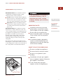
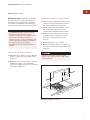
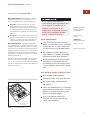
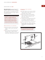
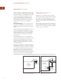
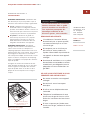
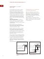
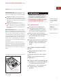
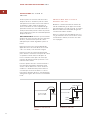
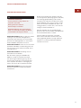
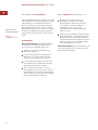
Record the model and serial numbers before
installing the cooktop. Both numbers are listed
on the rating plate, located on the underside of
the cooktop. Refer to the illustration below.
WOLF MULTI-FUNCTION COOKTOP
IMPORTANT NOTE:
Installation and service must be
performed by a qualified installer,
service agency or the gas supplier.
Do not store or use gasoline or
other flammable vapors and liquids
in the vicinity of this or any other
appliance.
A ventilation hood or downdraft
system is recommended (but not
required) for use with the Wolf gas
multi-function cooktop.
WHAT TO DO IF YOU SMELL GAS:
Do not try to light any appliance.
Do not touch any electrical switch.
Do not use any phone in your
building.
Immediately call your gas supplier
from a neighbor’s phone. Follow the
gas supplier’s instructions.
If you cannot reach your gas
supplier, call the fire department.
If the information in this book is
not followed exactly, a fire or
explosion may result, causing
property damage, personal injury
or death.
RATING PLATE
INFORMATION
Model Number
Serial Number
Rating plate location
Location of rating
plate under cooktop
ICBIM15/S

6
BEFO RE YOU START
Proper installation is your responsibility.
Have a qualified technician install this
cooktop. You must also ensure that electri-
cal installation is adequate and in compli-
ance with all local codes and ordinances.
Please check the product rating plate or Use
& Care Information for type of gas needed.
Proper gas supply connection must be
available; refer to Gas Supply Requirements
on page 10. Electrical ground is required;
see Electrical Requirements on page 11.
This cooktop is intended for indoor use.
Check the location where the cooktop will
be installed. The location should be away
from strong draft areas, such as windows,
doors and strong heating vents or fans. Do
not obstruct flow of combustion and
ventilation air.
Make sure you have everything necessary
for correct installation. It is the responsibil-
ity of the installer to comply with the instal-
lation clearances specified on the product
rating plate. The rating plate can be found
on the underside of the cooktop.
WOLF MUL TI-FUNCTIO N CO O KT OP

7
INSTALLATION INSTRUCTIONS
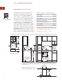
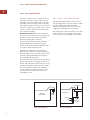
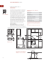
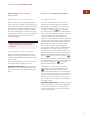
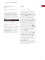
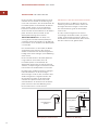
OVERHEAD CABINET DIMENSIONS
C)
Minimum spacing between overhead side
cabinets must be greater than or equal to
the nominal width of the module(s).
D)
Minimum 457 mm vertical distance from
the countertop to the bottom of side
cabinets within minimum side clearance.
E)
Minimum vertical distance between the
countertop and combustible materials
above the cooktop module must be
762 mm.
F)
Minimum 64 mm from rear wall.
G)
Maximum 330 mm depth of overhead and
side cabinets directly above and within side
clearance.
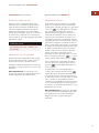
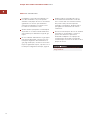
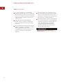
SITE PREPARATION
IMPORTANT NOTE:
Installation of the Wolf
gas multi-function cooktop must meet the
following location requirements. All dimen-
sions listed are minimum requirements for
safe operation. Refer to the illustration below.
To eliminate the risk of burns or fire by
reaching over heated surface units,
cabinet storage space located above the
surface units should be avoided. If
cabinet storage is to be provided, the risk
can be reduced by installing a ventilation
hood that projects horizontally a
minimum of 127 mm beyond the bottom
cabinets.
Failure to locate the cooktop module
without the proper clearances will result
in a fire hazard.
C
G
D
A
B
B
E
F
Minimum installation clearances
LOCATION IN COUNTERTOP
A)
Minimum flat countertop surface. Must be
equal to or greater than the width of the
module(s).
B)
Minimum 178 mm wide clearance from the
module side edge to any combustible
surface up to 457 mm above the countertop
(noted by shaded area).

8
WOLF MUL TI-FUNC TIO N CO OKT O P
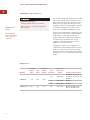
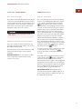
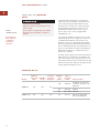
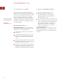
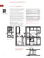
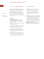
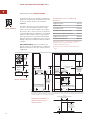
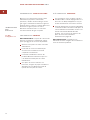
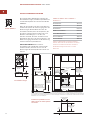
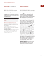
INSTALLATION SPECIFICATIONS
The illustrations below provide the overall
dimensions, installation specifications and
countertop cut-out for Model ICBIM15/S.
If the cooktop is not installed above an oven,
the gas service may be supplied through the
floor. When an oven is installed below the
cooktop, unless you are using cabinets deeper
than 610 mm, it is recommended that the
electrical supply be placed in the base cabinet
to the right of the oven. Refer to the Installation
Specifications illustration below for specifics
on placement of the electrical and gas supply.
IMPORTANT NOTE:
When multiple cooktops
and/or modules are installed side by side, refer
to the countertop cut-out dimensions on page 9.
E
127 mm
G
381 mm
381 mm
381
mm
LOCATION OF GAS SUPPLY
MAY ALSO EXTEND 127 mm ON
FLOOR FROM BACK WALL
178 mm*min
CUT-OUT TO
COMBUSTIBLE
MATERIALS
(BOTH SIDES)
356 mm
COOKTOP CUT-OUT
WIDTH
356 mm
COOKTOP CUT-OUT
WIDTH
838 mm
RECOMMENDED
CABINET WIDTH
457 mm
NOTE:Application shown allows for installation of two 381 mm modules side-by-side with 838 mm recommended cabinet width. 457 mm
recommended cabinet width for installation of single 381 mm cooktop or module. *Minimum clearance from both side edges of cooktop cut-out
to combustible materials up to 457 mm above countertop. **Minimum clearance from rear edge of cooktop cut-out to combustible materials up
to 457 mm above countertop.
489 mm
COOKTOP CUT-OUT
DEPTH
64 mm
min
914 mm
STANDARD
FLOOR TO
COUNTERTOP
HEIGHT
330 mm
max
762 mm
COUNTERTOP T
O
COMBUSTIBLE
MATERIALS
ABOVE COOKTO
P
64**
mm
127
mm
LOCATION OF GAS
SUPPLY MAY ALSO EXTEND
127 mm ON FLOOR
FROM BACK WALL
FRONT OF COUNTERTOP
64 mm
min
489 mm
COOKTOP
CUT-OUT DEPTH
381 mm
OVERALL WIDTH
533 mm
OVERALL
DEPTH
127 mm
MODEL ICBIM15/S DIMENSIONS
Overall Width 381 mm
Overall Height 127 mm
Overall Depth 533 mm
Minimum Cabinet Depth 578 mm
Minimum Height Clearance* 127 mm
Cut-Out Width 356 mm
Cut-Out Depth 489 mm
*A minimum height clearance of 140 mm is
required between countertop and any combustible
surface directly below the cooktop.
Unit dimensions may vary to
±
3 mm.
Overall Dimensions
Installation Specifications and
Countertop Cut-Out Dimensions
Model ICBIM15/S

9
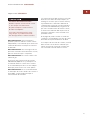
INSTALLATION INSTRUCTIONS
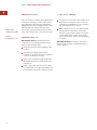
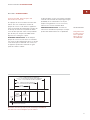
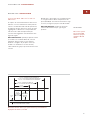
INSTALLATION OPTIONS
MULTIPLE COOKTOP INSTALLATION
If the multi-function cooktop is to be used with
any combination of additional cooktop units or
modules with a filler strip, the cut-out width is
calculated by adding the corresponding units'
cut-out dimensions plus 32 mm for each addi-
tional unit. Refer to the illustration below.
IMPORTANT NOTE:
When multiple cooktops
and/or modules are installed side by side, each
unit must have its own separate recommended
electrical circuit. When multiple gas cooktops
and/or modules are installed next to one
another, they can receive their gas supply from
a common line.
64 mm
min
FRONT OF COUNTERTOP
489 mm
CUT-OUT
DEPTH
743 mm
TWO MODULES WIDTH
1130 mm – THREE MODULES WIDTH OR
1124 mm – 762 mm COOKTOP AND ONE MODULE
1518 mm – FOUR MODULES WIDTH OR
1511 mm – 762 mm COOKTOP AND TWO MODULES OR
1276 mm – 914 mm COOKTOP AND ONE MODULE
356 mm
CUT-OUT
WIDTH
Countertop cut-out dimensions for installation of multiple cooktops
and/or modules
When two or more modules are installed
together, an integrated module filler strip
(IFILLER/S) is recommended. Contact your
Wolf dealer for information on these accessory
components.
IMPORTANT NOTE:
Review specific
installation instructions for product to product
capabilities.
ACCESSORIES
Optional acces-
sories are available
through your
Wolf dealer.

10
WOLF MUL TI-FUNC TIO N CO OKT O P
EXPLOSION HAZARD—
Securely tighten all gas connections.
Failure to do so can result in explosion,
fire or death.
GAS SUPPL Y REQUIREMENTS
The product rating plate, located on the under-
side of the cooktop, has information on the
type of gas that should be used. If this infor-
mation does not agree with the type of gas
available, contact your Wolf dealer. To obtain
local dealer information, visit the Locator
section of our website, wolfappliance.com.
An ISO 7-1 gas inlet thread is provided on all
units. Please contact your local Wolf dealer if
an ISO 228-1 or other gas inlet thread is
required. Pipe joint compounds suitable for
use with LP gas should be used. LP gas
suppliers usually determine the size and
materials used on the system.
If rigid pipe is used as a gas s upply line, a
combination of pipe fittings must be used to
obtain an in-line connection to the cooktop.
All strains must be removed from the supply
and gas lines so the cooktop will be level and
in line.
IMPORTANT
NOTE
This installation
must conform with
local codes and
ordinances.
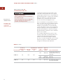
GAS RATING
Total Heat Electrical Types and
Output Gas Rating Gas Pressures
Model # (Gas) Units (Amps) Category (mbar) Country of Destination
AT, DK, EE, FI, GR, IE, IT,
I2H G20 at 20 LT, NO, PT, ES, SE, SI, SK,
ICBIM15/S 8.0 kW 0.17
GB & CH
I2E G20 at 20 DE & PL
I2E+ G20 at 20/25 BE & FR
ICBIM15/S-LP 581 g/h 0.17 I3P G31 at 37
BE,CZ,FR,GR,IE,NL,
NO, PT, ES, GB & CH

11
INSTALLATION INSTRUCTIONS
ELECTRICAL SHOCK HAZARD—
Plug into a grounded 3-prong electrical
outlet.
Do not remove ground prong.
Do not use an adapter.
Failure to follow these instructions can
result in electric shock, fire or death.
Electronic ignition systems operate within
wide voltage limits, but proper ground and
polarity are necessary. In addition to checking
that the electrical outlet provides 220-240 V AC
power and is correctly grounded, the outlet
must be checked by a qualified electrician to
see if it is wired with correct polarity.
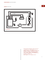
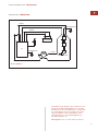
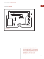
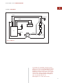
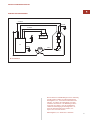
A wiring diagram covering the control circuit
for the Wolf multi-function cooktop model can
be found on page 15.
If an electrical outlet is not available, it is the
obligation of the customer to have a properly
grounded, 3-prong electrical outlet installed by
a qualified electrician.
IMPORTANT NOTE:
If codes permit and a
separate ground wire is used, it is recom-
mended that a qualified electrician determine
that the ground path is adequate.
IMPORTANT NOTE:
Check with a qualified
electrician if you are not sure whether the
cooktop is properly grounded.
IMPORTANT NOTE:
Do not ground to a gas
pipe.
A 220-240 V AC, 50/60 Hz, 15 amp electrical
supply is required. A time-delay fuse or circuit
breaker is recommended. It is recommended
that a separate circuit serving only this appli-
ance be provided.
IMPORTANT NOTE:
A ground fault circuit
interrupter (GFCI) is not recommended and
may cause interruption of operation.
ELECTRICAL REQUIREMENTS

12
WOLF MUL TI-FUNC TIO N CO OKT O P
COOKTOP INSTALLATION
Insert the cooktop into the countertop cut-out
opening. Center the cooktop in the opening
and make sure that the front edge of cooktop
is parallel to the front edge of the countertop.
Check that all required clearances are met. Use
a pencil to outline the rear edge of the cooktop
on the countertop. Remove the cooktop from
the countertop opening.
IMPORTANT NOTE:
When repositioning the
cooktop in the countertop cut-out opening, lift
the entire cooktop up from the opening to
prevent scratching the countertop.
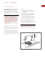
Remove the foam strip from the hardware
package. Apply the foam strip around the
bottom of the burner box flush with the edge
as shown in the illustration below.
Reinsert the cooktop into the countertop
opening. Check that the cooktop is parallel to
the front edge of the countertop. Lift the entire
cooktop to make adjustments and align the
rear edge with the pencil line.
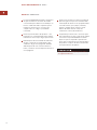
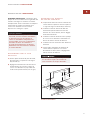
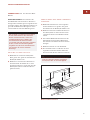
Attach the brackets to the burner box by insert-
ing the clips into the rectangular punchouts on
the left and right side of the burner box. Insert
the 89 mm clamping screws into the brackets.
Use a screwdriver to tighten the clamping
screws against the underside of the counter-
top. Refer to the illustration below. Do not
overtighten screws.
GAS SUPPLY LINE CONNECTION
Assemble the flexible metal connector from
the gas supply pipe to the gas entrance nipple.
You will need to determine the fittings
required, depending on the size of your gas
supply line and flexible metal connector.
Use a pipe-joint compound made for use with
natural and LP gas. If a flexible metal connec-
tor is used, be sure the tubing is not kinked.
Cooktop
Burner Box
Foam
Strip
Foam strip application
Burner Box
89 mm
Clamping
Screw
Countertop
Bracket
Clip
Bracket installation

13
INSTALLATION INSTRUCTIONS
COOKTOP INSTALLATION
GAS LEAK TESTING
Use a brush and liquid detergent to test all gas
connections for leaks. Bubbles around connec-
tions will indicate a leak. If a leak appears, shut
off gas valve controls and adjust connections.
Then check connections again. Clean all the
detergent solution from the cooktop.
COMPLETING THE INSTALLATION
Once the cooktop has been checked for any
gas leaks, plug the power supply cord into the
grounded electrical outlet.
Place the burner head on the burner base and
position the burner grate over the burner
assembly.
IMPORTANT NOTE:
Do not seal the cooktop
to the countertop. It must be removed if
service is necessary.
SURF A CE BURNERS
INITIAL LIGHTING
The cooktop burner uses an electronic igniter
in place of a standing pilot. When the cooktop
control knob is pushed in and turned to the
position, the system creates a spark to
light the burner. This sparking continues for 4
seconds or until the electronic ignition senses
a flame, which ever comes first. If the igniter
fails to ignite the gas in 4 seconds, the gas
safety shutoff valve will close, eliminating the
gas flow for 5 seconds. The valve will reopen
after the purge time of 5 seconds, and the
igniter will automatically attempt to re-ignite
the gas. This cycle of events is attempted 3
times. After the third attempt, in order for gas
to flow to the burner once again, the user must
return the knob to the position and then
turn the knob to the position.
To check operation of the cooktop burner, push
in and turn the control knob to the
position. The flame should light within four
seconds.
If the burner does not light properly, turn the
control knob to the position. Check that
the burner head is in the proper position.
Check that the power supply cord is plugged in
and that the circuit breaker or house fuse has
not blown. Check operation again; if the burner
does not light properly at this point, contact
your Wolf dealer or regional distributor.
IMPORTANT NOTE:
Initial lighting of the
cooktop burner may take slightly longer as air
in the system must be purged before gas can
be supplied to the burner.
Never test for a gas leak with a match or
other flame.

14
WOLF MUL TI-FUNC TIO N CO OKT O P
IF YOU NEED SERVIC E
For service in your area, contact either your
Wolf dealer or visit the Locator section of
our website, wolfappliance.com to find the
regional distributor by country.
When calling for service, you will need the
model and serial number of your multi-
function cooktop. Both numbers are listed
on the rating plate, located on the under-
side of the cooktop. Refer to the illustration
on page 5.
IMPORTANT NOTE:
Installation and service
must be performed by a qualified installer or
service agency.
COOKTOP REMOVAL
If it is necessary to remove the multi-function
cooktop for cleaning or service, shut off the
gas supply. Disconnect the gas and electric
supply. Remove the mounting brackets on the
right and left side of the burner box and
remove the cooktop. Reinstall in the reverse
order and check the gas connection for leaks.
TRO UB LESHOOTING
IMPORTANT NOTE:
If the multi-function
cooktop does not operate properly, follow
these troubleshooting steps:
Verify that power is being supplied to the
cooktop.
Check the gas supply and electrical
connections to ensure that the installation
has been completed correctly.
Refer to the Troubleshooting Guide in the
Wolf Multi-Function Cooktop Use & Care
Information.
If the cooktop still does not work, contact
your Wolf dealer or regional distributor. Do
not attempt to repair the cooktop yourself.
CONTACT
INFORMATION
Website:
wolfappliance.com

15
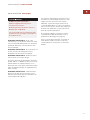
INSTALLATION INSTRUCTIONS
BLACK
WHITE
BLACK
WHITE
GAS VALVE
WHITE
BLACK
POWER CORD
GRN/YEL
GRN/YEL
DSI
RED
10 7
432
Model ICBIM15/S
WIRING DIAGRAM
The information and images in this book are the
copyright property of Wolf Appliance, Inc., an
affiliate of Sub-Zero, Inc. Neither this book nor any
information or images contained herein may be
copied or used in whole or in part without the
express written permission of Wolf Appliance, Inc.,
an affiliate of Sub-Zero, Inc.
©Wolf Appliance, Inc. all rights reserved.

Cuando consulte las instrucciones que aparecen
en esta guía, encontrará símbolos de ADVERTEN-
CIA y PRECAUCIÓN. Esta información en
recuadros es importante para instalar el equipo
de Wolf de forma segura y eficaz. Existen dos
tipos de posibles riesgos que pueden producirse
durante una instalación.
Otro tipo de anotación que es importante
resaltar es la que se incluye en NOTA IMPOR-
TANTE: En esta nota se resalta la información
que resulta especialmente importante para que
la instalación se realice sin problemas.
indica una situación en la que se pueden
sufrir heridas leves o provocar daños
secundarios al producto si no se siguen
las instrucciones.
indica peligro de que se produzcan heridas
personales graves o incluso puede provocar
la muerte si no se siguen las precauciones
especificadas.
WOLF
®
es una marca comercial registrada de Wolf Appliance, Inc.
INFORMACIÓN
DE CONTACTO
Página Web:
wolfappliance.com

17
REQUISITOS DE INSTALACIÓN
NOTA IMPORTANTE:
Esta instalación debe ser
realizada por un técnico cualificado o por un
técnico de mantenimiento autorizado de Wolf.
Instalador:
Lea las instrucciones de insta-
lación antes de llevar a cabo la instalación.
Guarde estas instrucciones para que el inspec-
tor local pueda utilizarlas como referencia y,
a continuación, entréguelas al propietario del
aparato.
Propietario:
Lea y guarde estas instrucciones
para que pueda utilizarlas como referencia en
el futuro y asegúrese de leer la guía de uso y
mantenimiento antes de utilizar el aparato.
NOTA IMPORTANTE:
Este aparato debe insta-
larse siguiendo las normativas nacionales corres-
pondientes. Se debe aplicar al aparato el voltaje,
la frecuencia y el amperaje adecuados desde una
instalación eléctrica resistente con toma de tierra
protegida por un fusible de retardo. El voltaje, la
frecuencia y el amperaje se muestran en la placa
de datos del producto.
Apunte la referencia del modelo y el número de
serie antes de instalar el aparato. Esta informa-
ción se muestra en la placa de datos del producto
situada en la parte inferior de la placa. Observe la
siguiente ilustración.
PLAC A MUL TIFUNC IÓ N DE WOLF
NOTA IMPORTANTE:
La instalación y el mantenimiento
deben ser realizados por un instalador
cualificado, por un centro de asisten-
cia técnica o por el proveedor de gas.
No almacene ni utilice gasolina ni
otros vapores ni líquidos inflamables
cerca de éste o de otros aparatos.
Se recomienda utilizar una campana
extractora o un ventilador de tiro
ascendente con la placa de gas multi-
función de Wolf, aunque no es obliga-
torio.
QUÉ SE DEBE HACER SI HUELE A GAS:
No encienda ningún aparato.
No toque ningún interruptor eléctrico.
No utilice ningún teléfono dentro
del edificio.
Llame inmediatamente a su proveedor
de gas desde el teléfono de un vecino.
Siga las instrucciones que le propor-
cione el proveedor de gas.
Si no le es posible ponerse en
contacto con el proveedor de gas,
llame a los bomberos.
Si no sigue exactamente las
instrucciones que se proporcionan
en esta guía, es posible que se
produzca un incendio o una
explosión lo cual puede provocar
daños en la propiedad, heridas
graves o incluso la muerte.
INFORMACIÓN
DE LA PLACA
DE DATOS
Referencia del
modelo
Númerodeserie
Ubicación de la placa de datos
Ubicación de la placa
de datos debajo de la
vitrocerámica
ICBIM15/S

18
ANTES DE COMENZAR
Es responsabilidad del propietario asegurarse
de que la instalación se realiza de manera
correcta. Esta placa debe ser instalada por un
técnico cualificado. Debe comprobar que la
instalación eléctrica es la correcta y que
cumple todos los códigos y normativas
nacionales.
Revise la placa de datos del producto o lea
la guía de uso y mantenimiento para obtener
información sobre el tipo de gas que necesita.
Debe disponer de una entrada de suministro
de gas; consulte la sección Requisitos del
suministro de gas en la página 22. También
debe disponer de una conexión eléctrica a
tierra; consulte la sección Requisitos eléctricos
en la página 23.
Esta placa está diseñada para que se utilice
en espacios interiores.
Inspeccione el lugar en el que va a instalar la
placa. El lugar en el que va a instalarla debe
estar alejado de áreas en las que pueda haber
corrientes fuertes, por ejemplo, ventanas,
puertas y salidas de aire caliente o venti-
ladores. No debe obstruir el flujo de
combustión ni el aire de ventilación.
Compruebe que tiene todo lo necesario para
que la instalación se lleve a cabo de la manera
correcta. Es responsabilidad del instalador
dejar los espacios requeridos para la insta-
lación que se especifican en la placa de datos
del producto. La placa de datos está ubicada
en la parte inferior del aparato.
PLAC A MUL TIFUNC IÓ N DE WOLF

19
INSTRUCCIONES DE INSTALACIÓN
MEDIDAS DE LOS ARMARIOS
SUPERIORES
C)
El espacio mínimo entre los armarios laterales
superiores debe ser igual o superior al ancho
nominal del módulo o módulos.
D)
Debe existir una distancia vertical mínima
de 457 mm desde la encimera hasta la parte
inferior de los armarios laterales con una
distancia lateral mínima.
E)
La distancia vertical mínima entre la encimera
y los materiales combustibles situados por
encima de la placa debe ser de 762 mm.
F)
Distancia mínima de 64 mm a la pared trasera.
G)
El fondo máximo de los armarios superiores
laterales situados por encima de la placa debe
ser de 330 mm con una distancia lateral
mínima.
PREPARACIÓN DEL
SITIO
NOTA IMPORTANTE:
La instalación de la placa
multifunción de gas de Wolf debe cumplir los
siguientes requisitos de colocación. Las medidas
que se especifican son las mínimas para que el
funcionamiento de la placa sea seguro. Observe
la siguiente ilustración.
Para eliminar el riesgo de sufrir quemaduras
o de que se produzca un incendio al
alcanzar las superficies calientes, debe
evitar colocar armarios por encima de los
módulos de superficie. Si va a colocar
armarios, el riesgo se puede reducir insta-
lando una campana de extracción que
sobresalga horizontalmente un mínimo de
127 mm de la parte inferior de los armarios.
Si no coloca el módulo de la placa siguien-
do las distancias de separación correctas,
es posible que se produzca un incendio.
C
G
D
A
B
B
E
F
Distancias mínimas de instalación
COLOCACIÓN EN LA ENCIMERA
A)
Superficie mínima de encimera plana. Debe
ser igual o superior al ancho del módulo o
módulos.
B)
Espacio mínimo de 178 mm desde el borde
lateral del módulo a cualquier superficie
combustible situada 457 mm por encima de la
encimera (área sombreada de la ilustración).

20
PLAC A MUL TIFUNC IÓ N DE WOLF
ESPECIFICACIONES DE LA
INSTALACIÓN
Las ilustraciones que se muestran a continuación
proporcionan las medidas totales, las especifica-
ciones de instalación y el c orte de la encimera
que corresponden al modelo CBIM15/S.
Si no instala la placa sobre un horno, el suminis-
tro de gas puede realizarse a través del suelo.
Cuando instale un horno debajo de una placa, se
recomienda que el suministro eléctrico se coloque
en el armario de la base situado a la derecha del
horno, a menos que esté utilizando armarios con
un fondo superior a 610 mm. Observe la ilus-
tración Especificaciones de instalación que se
muestra a continuación para obtener información
específica sobre la ubicación del suministro
eléctrico y de gas.
NOTA IMPORTANTE:
En el caso de que instale
varias placas y/o módulos juntos, consulte las
dimensiones del corte de la encimera en la página 21.
E
127 mm
G
381 mm
381 mm
381
mm
LA UBICACIÓN DE LA TOMA DE GAS
SE PUEDE EXTENDER 127 mm EN EL
SUELO DESDE LA PARED TRASERA
178 mm* mín
DESDE CORTE
ALOS
MATERIALES
INFLAMABLES
(AMBOS LADOS)
356 mm
ANCHURA DE CORTE
DE LA SUPERFICIE
DE COCCIÓN
356 mm
ANCHURA DE
CORTE DE LA
SUPERFICIE
DE COCCIÓN
838 mm
ANCHURA DEL ARMARIO
RECOMENDADO
457 mm
NOTA: La aplicación que se muestra permite la instalación de dos módulos contiguos de 381 mm con un armario con una anchura recomendada de 838
m
457 mm de anchura de armario recomendada para la instalación de un solo módulo o superficie de cocción de 381 mm. *Espacio mínimo desde ambos
bordes laterales del corte de la superficie de cocción hasta la superficie inflamable situada a 457 mm por encima de la encimera. **Espacio mínimo desde
el borde trasero del corte de la superficie de cocción a la superficie inflamable situada a 457 mm sobre la encimera.
489 mm
PROFUNDIDAD DE
CORTE DE LA
SUPERFICIE
DE COCCIÓN
64 mm
mín
914 mm
ALTURA
ESTÁNDAR
DEL SUELO A
LA ENCIMERA
330 mm
máx
762 mm
ENCIMERA A
MATERIALES
COMBUSTIBLES
SOBRE
LA SUPERFICIE
DE COCCIÓN
64**
mm
127
mm
LA UBICACIÓN DE LA TOMA
DE GAS SE PUEDE EXTENDER
127 mm EN EL SUELO DESDE
LA PARED TRASERA
PARTE DELANTERA DE LA ENCIMERA
64 mm
mín
489 mm
PROFUNDIDAD
DE CORTE
DE LA SUPERFICIE
DE COCCIÓN
381 mm
ANCHURA TOTAL
533 mm
PROFUNDIDAD
TOTAL
127 mm
DIMENSIONES DEL MODELO
ICBIM15/S
Anchura total 381 mm
Altura total 127 mm
Profundidad total 533 mm
Fondo mínimo del armario 578 mm
Espacio de altura mínimo* 127 mm
Ancho del corte 356 mm
Profundidad del corte 489 mm
*Se necesita dejar un espacio mínimo de altura
de 140 mm entre la placa y cualquier superficie
combustible que se encuentre justo debajo de la
placa.
Las medidas de la unidad pueden variar
±
3mm.
Medidas totales
Especificaciones de la instalación
Medidas de corte de la encimera
Modelo ICBIM15/S

21
INSTRUCCIONES DE INSTALACIÓN
OPCIONES DE INSTALACIÓN
INSTALACIÓN DE VARIAS SUPERFICIES
DE COCCIÓN
Si la placa multifunción se va a utilizar con
otras combinaciones de módulos o unidades de
cocción adicionales con un embellecedor, el
ancho del corte se calcula sumando las medidas
de corte de las unidades correspondientes más
32 mm por cada unidad adicional. Observe la
siguiente ilustración.
NOTA IMPORTANTE:
En el caso de que se
instalen varias placas y/o módulos juntos, es
recomendable que cada unidad tenga su propio
circuito eléctrico. Cuando se instalen varias
placas y/o módulos de gas de manera contigua,
todos pueden recibir el suministro de gas de una
línea común.
64 mm
mín
PARTE DELANTERA DE LA ENCIMERA
489 mm
PROFUNDIDAD
DEL CORTE
743 mm
ANCHURA DE DOS MÓDULOS
1 130 mm – ANCHURA DE TRES MÓDULOS O
1 124 mm – 762 mm SUPERFICIE DE COCCIÓN
YUNMÓDULO
1 518 mm – ANCHURA DE CUATRO M
Ó
DULOS
Ó
1 511 mm – 762 mm SUPERFICIE DE COCCIÓN Y DOS MÓDULOS O
1 276 mm – 914 mm SUPERFICIE DE COCCIÓN Y UN MÓDULO
356 mm
ANCHURA
DE CORTE
Dimensiones de corte de la encimera para la instalación de varias
superficies de cocción y/o módulos.
Cuando se instalen dos o más módulos juntos, se
recomienda utilizar un embellecedor de módulo
integrado (IFILLER/S). Póngase en contacto con
su distribuidor de Wolf para obtener información
sobre estos accesorios.
NOTA IMPORTANTE:
Revise las instrucciones
de instalación específicas para conocer las capaci-
dades de cada uno de los productos.
ACCESORIOS
Podrá disponer
de accesorios
opcionales a través
de su distribuidor
de Wolf.
Seite wird geladen ...
Seite wird geladen ...
Seite wird geladen ...
Seite wird geladen ...
Seite wird geladen ...
Seite wird geladen ...
Seite wird geladen ...
Seite wird geladen ...
Seite wird geladen ...
Seite wird geladen ...
Seite wird geladen ...
Seite wird geladen ...
Seite wird geladen ...
Seite wird geladen ...
Seite wird geladen ...
Seite wird geladen ...
Seite wird geladen ...
Seite wird geladen ...
Seite wird geladen ...
Seite wird geladen ...
Seite wird geladen ...
Seite wird geladen ...
Seite wird geladen ...
Seite wird geladen ...
Seite wird geladen ...
Seite wird geladen ...
Seite wird geladen ...
Seite wird geladen ...
Seite wird geladen ...
Seite wird geladen ...
Seite wird geladen ...
Seite wird geladen ...
Seite wird geladen ...
Seite wird geladen ...
Seite wird geladen ...
Seite wird geladen ...
Seite wird geladen ...
Seite wird geladen ...
Seite wird geladen ...
Seite wird geladen ...
Seite wird geladen ...
Seite wird geladen ...
Seite wird geladen ...
-
 1
1
-
 2
2
-
 3
3
-
 4
4
-
 5
5
-
 6
6
-
 7
7
-
 8
8
-
 9
9
-
 10
10
-
 11
11
-
 12
12
-
 13
13
-
 14
14
-
 15
15
-
 16
16
-
 17
17
-
 18
18
-
 19
19
-
 20
20
-
 21
21
-
 22
22
-
 23
23
-
 24
24
-
 25
25
-
 26
26
-
 27
27
-
 28
28
-
 29
29
-
 30
30
-
 31
31
-
 32
32
-
 33
33
-
 34
34
-
 35
35
-
 36
36
-
 37
37
-
 38
38
-
 39
39
-
 40
40
-
 41
41
-
 42
42
-
 43
43
-
 44
44
-
 45
45
-
 46
46
-
 47
47
-
 48
48
-
 49
49
-
 50
50
-
 51
51
-
 52
52
-
 53
53
-
 54
54
-
 55
55
-
 56
56
-
 57
57
-
 58
58
-
 59
59
-
 60
60
-
 61
61
-
 62
62
-
 63
63


Wolf Gas Multi-Function Cooktop Installation Instructions Manual
- Typ
- Installation Instructions Manual
in anderen Sprachen
- français: Wolf Gas Multi-Function Cooktop
- español: Wolf Gas Multi-Function Cooktop
- italiano: Wolf Gas Multi-Function Cooktop
Verwandte Artikel
-
Wolf ICBMM15T/S Installationsanleitung
-
-
-
-
-
Wolf ICBCT30IU Benutzerhandbuch
-
-
-
Wolf ICBCG365P/S Installationsanleitung
-