
CARATTERISTICHE GENERALI
ITALIANO
F U S I B I L I L I N E A 5 A
F U S . A C C E S S O R I 1 A
T . C . A .
1 2
A F 4 3 S / S M
Z B X 6
Q U A D R O C O M A N D O
Descrizione scheda di comando
La scheda comando ZBX6 è adatta al
comando di automazioni scorrevoli
alimentati a 230V monofase della serie
BX-A/BX-B.
La scheda va inserita e fissata nel conte-
nitore porta-schede del motoriduttore
(vedi descrizione di montaggio a pag.6),
ed alimentata con una tensione di 230V
(a.c.) nei morsetti L1 e L2.
É protetta in ingresso con due fusibili da
5A, mentre i dispositivi di comando a
bassa tensione (24V) sono protetti con
fusibile da 1A.
La potenza complessiva degli accessori
(24V) non deve superare i 20W.
Il tempo lavoro è fisso a 80 secondi.
Sicurezza
Le fotocellule possono essere collegate e
predisposte per:
-
Riapertura
in fase di chiusura (2-C1), le
fotocellule rilevando un ostacolo durante
la fase di chiusura del
cancello, provocano l'inver-
sione di marcia fino alla
completa apertura;
-
Stop totale
(1-2), arresto
del cancello con l'esclusione
del ciclo di chiusura automa-
tica, per riprendere il movimento del
cancello, agire sulla pulsantiera o sul
radiocomando;
Altre funzioni
-
Chiusura automatica.
Il temporizzatore
di chiusura automatica si autoalimenta a
finecorsa in apertura. Il tempo prefissato
regolabile, è in ogni modo subordinato
dall'intervento di eventuali accessori di
sicurezza e si esclude dopo un intervento
di "stop" o in mancanza d'energia elettri-
ca;
-
"Uomo presente"
. Funzionamento del
cancello mantenendo premuto il pulsante
(esclude la funzione del radiocomando);
Regolazioni
- Tempo chiusura automatica;
Attenzione: prima di intervenire all’inter-
no dell’apparecchiatura, togliere la
tensione di linea.
ZBX6
Documentazione
Tecnica
S18
rev. 1.0
© CAME 05/99
319S18
SCHEDASCHEDA
SCHEDASCHEDA
SCHEDA
COMANDOCOMANDO
COMANDOCOMANDO
COMANDO
CONTROL BOARD
CARTECARTE
CARTECARTE
CARTE
DEDE
DEDE
DE
COMMANDECOMMANDE
COMMANDECOMMANDE
COMMANDE
STEUERPLATINE
TARJETATARJETA
TARJETATARJETA
TARJETA
DEDE
DEDE
DE
MANDOMANDO
MANDOMANDO
MANDO
SERIESERIE
SERIESERIE
SERIE
Z / Z /
Z / Z /
Z /
Z SERIES
/
SÉRIESÉRIE
SÉRIESÉRIE
SÉRIE
Z / Z /
Z / Z /
Z /
BAUREIHE Z /
SERIESERIE
SERIESERIE
SERIE
Z Z
Z Z
Z
www.came.co.uk Tech suppport : 0870 012 9000

-2-
GENERAL CHARACTERISTICS
ENGLISH
Description of control panel
The ZBX6 control board is used as a
remote control for BX-A/BX-B series
230V single-phase automated sliding
gates.
The board is introduced and fixed in
place in the gearmotor's circuit board
holder (see assembly description on
page 6), at 230V (a.c.) in terminals L1
and L2.
The inlet is protected with two 5A fuses,
while the low voltage (24V) control
devices are protected with a 1A fuse.
The accessorie's total capacity (24V)
should not exceed 20W.
Fixed operating time of 80 seconds.
Safety
Photocells can be connected to abtain:
-
Re-opening
during closure (2-C1), if
the photocells identify an obstacle while
the gate is closing, they will reverse the
direction of movement until the gate is
completely open;
-
Total stop
(1-2), shutdown of gate
movement without automatic closing, a
pushbutton or radio remote control must
be actuated to resume movement.
Other functions
-
Automatic closing.
The automatic
closing timer is automatically activated
at the end of the opening cycle. The
preset, adjustable automatic closing
time is automatically interrupted by the
activation of any safety system, and is
deactivated after a STOP command or
in case of power failure;
-
"Operator present"
. Gate operates only
when the pushbutton is held down (the
radio remote control system is
deactivated);
Adjiustments
- Automatic closure time;
IMPORTANT: Disconnect the unit from
the main power lines before carrying out
any operation inside the unit.
www.came.co.uk Tech suppport : 0870 012 9000

-3-
CARACTÉRISTIQUES GÉNÉRALES
FRANÇAIS
Description armoire de commande
La carte de commande ZBX6 est
indiquée pour commander les
automatismes coulissants alimentés à
230V et monophasés de la série BX-A/
BX-B.
Introduire la carte et la fixer dans le
porte-cartes du motoréducteur (voir
description du montage à la page 6).
La carte est alimentée avec une tension
de 230V (c.a.) dans les bornes L1 et L2.
Elle est protégée à l'entrée par deux
fusibles de 5A, tandis que les dispositifs
de commande à basse tension (24V)
sont protégés par un fusible de 1A.
La puissance totale des accessoires
(24V) ne doit pas dépasser 20W.
Temps de fonctionnement fixe de 80
sec.
Sécurité
Il est possible de brancher des
photocellules et de les programmer
pour:
-
Réouverture
en phase de fermeture
(2-C1), les cellules photoélectriques
provoquent l'inversion de marche
jusqu'à l'ouverture complète si elles
relèvent un obstacle durant la phase de
fermeture du portail;
-
Stop total
(1-2), arrêt du portail et
désactivation d’un éventuel cycle de
fermeture automatique; pour activer de
nouveau le mouvement, il faut agir sur
les boutons-poussoirs ou sur la
radiocommande.
Autres fonctions
-
Fermeture automatique.
Le tempo-
risateur de fermeture automatique est
autoalimenté à la fin du temps de la
course en ouverture. Le temps réglable
est programmé, cependant, il est
subordonné à l’intervention d’éventuels
accessoires de sécurité et il est exclu
après une intervention de “stop” ou en
cas de coupure de courant;
-
Fonction “homme mort”
. Fonc-
tionnement du portail en maintenant
appuyé le bouton-poussoir (exclut la
fonction de la radiocommande);
Réglages
- Temps de fermeture automatique;
ATTENTION: avant d'intervenir à
l'intérieur de l'appareillage, couper la
tension de ligne.
www.came.co.uk Tech suppport : 0870 012 9000

-4-
Beschreibung des Steuergeräts
Die Steuerplatine ZBX6 eignet sich zur
Steuerung der Automatik von
Schiebetoren der Baureihe BX-A und
BX-B mit 230V Einphasenversorgung.
Die Karte wird in das Kartenhalter-
Gehäuse des Getriebemotors
eingesetzt und dort befestigt (siehe
Montageanleitung auf S.6) und mit einer
Spannung von 230V (WS) über die
Klemmen L1 und L2 gespeist.
Die Karte ist am Eingang mit 2 5A-
Sicherungen geschützt, die Nieder-
spannungs-Steuervorrichtungen (24V)
dagegen sind mit einer 1A-Sicherung
geschützt.
Die Gesamtleistung der Zubehörteile
(24V) darf 20W nicht übersteigen.
Feste Laufzeit von 80 Sekunden.
Sicherheitsvorrichtungen
Die Lichtschranken können für
folgende Funktionen angeschlossen
bzw. vorbereitet werden:
-
Wiederöffnen
beim Schließen (2-C1),
die Lichtschranken ermitteln ein
Hindernis während des schließens vom
Tor und lösen die Umkehr der
Laufrichtung vom Tor aus, bis dieses
wieder vollständig geöffnet ist;
-
Totalstop
(1-2), sofortiger Stillstand des
Tores mit Ausschluß eventueller
Schließautomatik: Fortsetzung des
Torlaufs über Drucktaster- bzw. Funk-
sendersteuerung;
Andere Wahlfunktionen
-
Schließautomatik
. Der
Schließautomatik-Zeischalter speist sich
beim Öffnen am Ende der Torlaufzeit
selbst . Die voreingestellte Zeit ist auf
jeden Fall immer dem Eingriff
eventueller Sicherheitsvorrichtungen
untergeordnet und schließt sich nach
einem “Stop”-Eingriff bzw. bei
Stromausfall selbst aus;
-
Funktion“Bedienung vom Steuerpult”
.
Torbetrieb durch Drucktasterbetätigung
(Funkfernsteuerung ausgeschlossen);
Einstellungen
- Zeit für das automatische Schließen;
ACHTUNG: Vor Eingriff im Innern des
Gerätes den Netzstecker ziehen.
ALLGEMEINE MERKMALE
DEUTSCH
www.came.co.uk Tech suppport : 0870 012 9000

-5-
Descripción cuadro de mando
La tarjeta de mando ZBX6 es idónea
para el accionamiento de automa-
tizaciones de puertas correderas
alimentadas a 230V monofásica de la
serie BX-A/BX-B.
La tarjeta se introduce y fija en la caja
respectiva en el motorreductor (véase
descripción montaje en pág.6), y se
alimenta con una tensión de 230V (c.a.)
en los bornes L1 y L2.
La tarjeta está protegida en la entrada
por dos fusibles de 5A, mientras que los
dispositivos de accionamiento de baja
tensión (24V) están protegidos por
fusible de 1A.
La potencia total de los accesorios (24V)
no tiene que superar los 20W.
Tiempo de trabajo fijo a 80 segundos.
Seguridad
Las fotocélulas pueden estar
conectadas y predispuestas para:
-
Reapertura
en la fase de cierre (2-C1),
las fotocélulas detectan un obstáculo
durante el cierre de la puerta, provocan-
do la inversión de marcha hasta la
apertura completa;
-
Parada total
(1-2), parada de la puerta
excluyendo el posible ciclo de cierre
automático; para reactivar el movimiento
es preciso actuar en el teclado o en el
mando a distancia);
Otras funciones
-
Cierre automático
. El temporizador de
cierre automático se autoalimenta en
fin-de-tiempo carrera en fase de apertu-
ra. El tiempo prefijado regulable, sin
embargo, está subordinado a la
intervención de posibles accesorios de
seguridad y se excluye después de una
intervención de parada o en caso de
falta de energía eléctrica;
-
Función a "hombre presente"
. Fun-
cionamiento de la puerta manteniendo
pulsada la tecla (excluye la función del
mando a distancia).
Regulaciones
- Tiempo de cierre automático;
ATENCION: antes de actuar dentro del
aparado, quitar la tensión de línea.
CARACTERISTICAS GENERALES
ESPANOL
www.came.co.uk Tech suppport : 0870 012 9000

-6-
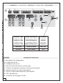
DESCRIZIONE DI MONTAGGIO -
ASSEMBLY DESCRIPTION
- DESCRIPTION DU MONTAGE
MONTAGEANLEITUNG -
DESCRIPTIÓN DEL MONTAJE
-Aprire lo sportello accesso sblocco, allentare
la vite del coperchio quadro comando e levar-
lo (1).
-Rimuovere il copri-scheda dalla piastra di
supporto quadro comando (2).
-Agganciare e fissare la scheda ZBX6 nella
piastra di supporto quadro comando con le viti
predisposte (3).
-Riposizionare il supporto copri-schede (4).
-Procedere al collegamento elettrico, fissare il
coperchio del quadro comando e chiudere lo
sportello accesso blocco (5).
ITALIANO
ENGLISH
1
2
-Open the release access door, loosen the
screws of the control panel cover and lift it (1).
-Remove the circuit board cover from the
control panel support plate (2).
-Hook and fix the ZBX6 board to the control
panel support plate with the appropriate screws
(3).
-Reposition the circuit board cover support
(4).
-Proceed with the electric connection, replace
the control panel cover and close the release
access door (5).
FRANÇAIS
-Ouvrir le volet d'accès au déblocage,
desserrer la vis du couvercle de l'armoire de
commande et l'enlever (1).
-Enlever le protège-carte de la plaque qui
soutient l'armoire de commande (2).
www.came.co.uk Tech suppport : 0870 012 9000

-7-
3
DEUTSCH
ESPANIOL
-Öffnen Sie die Klappe, die Zugriff auf die
Schalttafel gibt. Lösen Sie die Schrauben von
der Abdeckung der Schalttafel und nehmen
Sie die Abdeckung ab (1).
-Nehmen Sie die Kartenabdeckung von der
Halterungsplatte der Schalttafel ab (2).
-Stecken Sie die Karte ZBX6 in die
Halterungsplatte der Schalttafel und befestigen
Sie die mit den entsprechenden Schrauben
(3).
-Bringen Sie die Kartenabdeckung wieder an
(4).
-Führen Sie den Stromanschluß durch.
Bringen Sie dann die Abdeckung wieder auf
der Schalttafel an und schließen Sie die Klappe
wieder (5).
-Abra la puerta de acceso al desbloqueo,
afloje el tornillo de la tapa del cuadro de
mando y quítelo (1).
-Quite el cubretarjeta de la placa de soporte
del cuadro de mando (2).
-Enganche y fije la tarjeta ZBX6 a la placa de
soporte del cuadro de mando, con los tornillos
suministrados (3).
-Vuelva a colocar el soporte cubretaryeta (4).
-Realice la conexión eléctrica, fije la tapa del
cuadro de mando y cierre la puerta de acceso
al desbloqueo (5).
4
5
-Accrocher et fixer la carte ZBX6 dans la
plaque qui soutient l'armoire de commande
avec les vis prévues à cet effet (3).
-Remettre le support protège-cartes (4).
-Effectuer le branchement électrique, fixer le
couvercle de l'armoire de commande et
refermer le volet d'accès au blocage (5).
www.came.co.uk Tech suppport : 0870 012 9000

-8-
SCHEDA BASE -
MOTHERBOARD
- CARTE BASE -
GRUNDPLATINE
- TARJETA BASE
F U S I B I L I L I N E A 5 A
F U S . A C C E S S O R I 1 A
T . C . A .
1 2
A F 4 3 S / S M
1
2
3
4
5
6
8
7
9
9
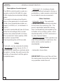
COMPONENTI PRINCIPALI
1 Morsettiere di collegamento
2 Fusibili di linea 5A
3 Fusibile accessori 1A
4 Pulsante memorizzazione codice radio
5 Trimmer di regolazione tempo di chiusura automatica
6 Selettore funzioni a 2 dip (vedi pag.10)
7 Innesto scheda radiofrequenza (vedi tabella)
8 LED segnalazione
9 Asolature per fissaggio scheda
ITALIANO
zHM/azneuqerF
zHM/ycneuqerF
zHM/ecneuqerF
zHM/zneuqerF
zHM/aicneucerF
azneuqerfoidaradehcS
draobycneuqerfoidaR
ecneuqérfoidaretraC
enitalP-zneuqerfknuF
aicneucerfoidaratejraT
erorittemsarT
rettimsnarT
ruettemE
rednesknuF
rosimsnarT
29.334MA MS34FA/S34FA POT/MAT
009.03MF 051FA/031FA MFT
www.came.co.uk Tech suppport : 0870 012 9000

-9-
HAUPTKOMPONENTEN
1 AnschlußKlemmenleiste
2 Hauptsicherung 5A
3 Zubehör-Sicherung 1A
4 Knöpfe zum Abspeicher der Radiocodes
5 Trimmer zur Einstellung Schließautomatik
6 Wählschalter für Funktionen mit 2 Dip (sehen S.10)
7 Steckanschluß Funkfrequenze-Platine AF (sehen Tabelle)
8 LED Kontrolleuchte zur Anzeige
9 Lochung für die Befestigung der Karte
PRINCIPALES COMPONENTES
1 Caja de bornes para las conexiónes
2 Fusibles de línea 5A
3 Fusible accesorios 1A
4 Teclas de memorización del código radio
5 Trimmer de regulación tiempo cierre automático
6 Selector de funciones con 2 dip (vedas pag.10)
7 Conexión tarjeta radiofrecuencia AF (vedas tabla)
8 LED de señal
9 Perforaciones para fijación de la tarjeta
MAIN COMPONENTES
1 Terminal block for external conections
2 Line fuses, 5A
3 Fuse on accessory power line, 1A
4 Radio-code save buttons
5 Trimmer for adjustment automatic closing
6 2-dip function switch (see pag.10)
7 Socket AF radiofrequency board (see table)
8 Signal LED
9 Grooves for board positioning
PRINCIPAUX COMPOSANTS
1 Plaque à bornes de connexion
2 Fusibles de ligne 5A
3 Fusible accessoires 1A
4 Boutons-poussoir mémorisation code radio
5 Trimmer de réglage fermeture automatique
6 Selecteur de fonctions à 2 interrupteurs à positions multiples (voir pag.10)
7 Branchement carte radiofréquence AF (voir tableau)
8 LED de signalisation
9 Fentes pour fixer la carte
ENGLISH
FRANÇAIS
DEUTSCH
ESPANOL
www.came.co.uk Tech suppport : 0870 012 9000

-10-
FUSIBILILINEA 5A
FUS.AC C E SSO RI1A
T.C.A.
1 2
AF43S/SM
L1 L2 U V W E1
11 1 2 7 C 110
FA FC F
1 OFF "Uomo presente" (esclude il fun-
zionamento del radiocomando)
disattivato; (1ON - attivato)
2 ON Chiusura automatica attivata;
(2OFF - disattivata)
ITALIANO
ENGLISH
ESPANOLDEUTSCH
REGOLAZIONI -
ADJUSTMENTS
- RÉGLAGES -
EINSTELLUNGEN
- REGULACIONES
ITALIANO
FRANÇAIS
Trimmer T.C.A.
= Regolazione tempo di
chiusura automatica da un minimo di 3
secondi a un massimo di 140 secondi.
ENGLISH
ESPANOL
DEUTSCH
FRANÇAIS
SELEZIONI FUNZIONI -
SELECTION OF FUNCTIONS
- SÉLECTION FONCTIONS
FUNKTIONSWAHL
- SELECCIÓN DE LAS FUNCIONES
DIP-SWITCH 2 VIE
/ 2-WAY DIP-SWITCH
DIP-SWITCH 2 VOIES
ZWEIWEG-DIP-SWITCH /
DIP-SWITCH 2 VÍAS
1 OFF "Operator present" (radio remote
control is deactivated when
function is selected) disabled;
(1ON - enabled)
2 ON Automatic closing enabled; (2OFF
- disabled)
1 OFF "Homme mort" (exclut la fonction
radiocommande) désactivèe;
(1ON-activée)
2 ON Fermeture automatique activée;
(2OFF - désactiée)
1 OFF Bedienung vom "Steuerpul" (bei
Wahl dieser Betriebsart wird die
Funkfernsteuerung ausgesch.)
deaktiviert; (1ON - aktiviert)
2 ON Schließautomatikaktiviert;(2OFF
- deaktiviert)
1 OFF "Hombre presente" (escluye la
función del mando de radio)
desactivado; (1ON - activado)
2 ON Cierre automático activado;
(2OFF - desactivado)
Trimmer T.C.A.
= Adjusts automatic
closing time from a minimum of 3 seconds
to a maximum of 140 seconds.
Trimmer T.C.A.
= Timer, auf dem die
Verzögerung für das automatische
Schlißen mit mindestens 3 Sekunden und
höchstens 140 Sekunden eingestellt
werden kann.
Trimmer T.C.A.
= Réglage du temps de
fermeture automatique d'un minimum de
3 secondes à un maximun de 140
secondes.
Trimmer T.C.A.
= Réglage du temps de
fermeture automatique d'un minimum de
3 secondes à un maximun de 140
secondes.
ON
OFF
1 2
FUSIBILILINEA 5A
FUS.AC C E SSO RI1A
T.C.A.
1 2
AF43S/SM
L1 L2 U V W E1
11 1 2 7 C 110
FA FC F
REGULACIÓN TRIMMERS
EINTELLUNG TRIMMERS
RÉGLAGE TRIMMERS
TRIMMERS ADJUSTMENT
REGOLAZIONE TRIMMERS
T . C . A .
www.came.co.uk Tech suppport : 0870 012 9000

-11-
Gruppo motore-finecorsa già collegati per montaggio a sinistra vista interna.
Per eventuale montaggio a destra:
- invertire FA-FC dei finecorsa sulla morsettiera;
- invertire le fasi U-V del motore sulla morsettiera.
The motor and limit switch unit are wired at the factory for mounting on the left-hand
side of the gate (as seen from the inside). If right-hand installation is desired:
- invert limit switch connections FA-FC on the terminal block;
- invert motor phase connections U-V on the terminal block.
Groupe moteur-fins de course déjà branchés pour le montage à gauche - vue de
l'intérieur.
Pour un éventuel montage à droite:
- inverser FA-FC des fins de course sur la plaque à bornes;
- inverser les phases U-V du moteur sur la plaque à bornes.
Das Motor-Anschlag-Aggregat schon für die Montage auf der linken Seite
angeschlossen, interne Ansicht.
Für eine eventuelle Montage auf der rechten Seite:
- die Öffnungs- und Schließungsphasen auf dem Klemmbrett invertieren;
- die U-V Phasen des Motors auf dem Klemmen tauschen.
Grupo motor-fin de carrera ya conectados para el montaje a la izquierda vista interior.
Para el eventual montaje a la derecha:
- invertir FA-FC de los fines de carrera en el cuadro de bornes;
- invertir las fases U-V del motor en el cuadro de bornes.
COLLEGAMENTO FINECORSA -
LIMIT SWITCH CONNECTIONS
- BRANCHEMENT DE COURSE
ENDAUSSCHALTER-ANSCHLUSS
- CONEXION FINAL DE CARRERA
ITALIANO
ENGLISH
FRANÇAIS
DEUTSCH
ESPANOL
Gruppo finecorsa
Limit switch unit
Groupe fins de course
Anschlag-Gruppe
Grupo fin de carrera
Motore monofase 230V
230V single-phase motor
Moteur monophasé 230V
Einphasiger Motor 230V
Motor monofásico de 230V
Motore monofase 230V
230V single-phase motor
Moteur monophasé 230V
Einphasiger Motor 230V
Motor monofásico de 230V
Gruppo finecorsa
Limit switch unit
Groupe fins de course
Anschlag-Gruppe
Grupo fin de carrera
COMCOM
COMCOM
COM
U W VU W V
U W VU W V
U W V
NCNC
NCNC
NC
NCNC
NCNC
NC
NCNC
NCNC
NC
NCNC
NCNC
NC
U W VU W V
U W VU W V
U W V
COMCOM
COMCOM
COM
FF
FF
F
FF
FF
F
CC
CC
C
FF
FF
F
AA
AA
A
FF
FF
F
CC
CC
C
FF
FF
F
AA
AA
A
FF
FF
F
MM
MM
M
MM
MM
M
www.came.co.uk Tech suppport : 0870 012 9000

-12-
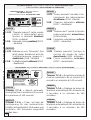
COLLEGAMENTI ELETTRICI -
ELECTRICAL CONNECTIONS -
BRANCHEMENTS ÉLECTRIQUES
ELEKRISCHE ANSCHLÜSSE -
CONEXIONES ELÉCTRICAS
W
E1
U
W
V
L1
L2
10
11
Alimentazione 230V (a.c.)
230V (a.c.) power input
Alimentation 230V (c.a.)
Stromversorgung 230V (Wechselstrom)
Alimentación 230V (a.c.)
Motore monofase 230V (a.c.)
230V (a.c.) single-phase motor
Moteur monophasé 230V (c.a.)
Einphasenmotor 230V (Wechselstrom)
Motor monofásico 230V (a.c.)
Uscita 230V (a.c.) in movimento
(es.lampeggiatore - max. 25W)
230V (a.c.) output in motion
(e.g. flashing light - max. 25W)
Sortie 230V (c.a.) en mouvement
(ex. branchement clignotant - max. 25W)
Ausgang 230V (Wechselstrom) in Bewegung
(z.B. Blinker-Anschluß - max. 25W)
Salida de 230V (a.c.) en movimento
(p.ej. conexión lámpara intermitente - max. 25W)
Alimentazione accessori 24V (a.c.) max. 20W
24V (a.c.)Powering accessories (max 20W)
Alimentation accessoires 24V (c.a.) max. 20W
Zubehörspeisung 24V (Wechselstrom) max. 20W
Alimentación accesoios 24V (a.c.) max. 20W
Lampada spia (24V-3W max.) "cancello aperto"
(24V-3W max.) "gate-opened" signal lamp
Lampe-témoin (24V-3W max.) "portail ouverture"
Signallampe (24V-3W max.) "Tor Öffnen"
Lámpara indicadora (24V-3W max.) "puerta abierta"
11
FC
L1 L2 U V W E1
11 1 2 7 C110
FA FC F
www.came.co.uk Tech suppport : 0870 012 9000

-13-
11
FA
2
7
Lampada spia (24V-3W max.) "cancello chiuso"
(24V-3W max.) "gate-closed" signal lamp
Lampe-témoin (24V-3W max.) "portail fermeture"
Signallampe (24V-3W max.) "Tor Schließen"
Lámpara indicadora (24V-3W max.) "puerta cierre"
Pulsante stop (N.C.)
Pushbutton stop (N.C.)
Bouton-poussoir arrêt (N.F.)
Stop-Taste (N.C.)
Pulsador de stop (N.C.)
Contatto radio e/o pulsante per comando
Contact radio and/or button for control
Contact radio et/ou poussoir pour commande
Funkkontakt und/oder Taste Steuerart
Contacto radio y/o pulsador para mando
Contatto (N.C.) di «riapertura durante la chiusura»
Contact (N.C.) for «re-opening during the closing»
Contact (N.F.) de «réouverture pendant la fermeture»
Kontakt (Ruhekontakt) «Wiederöffnen beim Schliessen»
Contacto (N.C.) para la «apertura en la fase de cierre»
Collegamento finecorsa apre (vedi pag.11)
Connection limit switch opens (see pag.11)
Connexion fin de course ouverture (voir pag.11)
Anschluß Endschallter Öffnung (siehe S.11)
Conexión fin de carrera apertura (véase pàg.11)
Collegamento finecorsa chiude (vedi pag.11)
Connection limit switch closes (see pag.11)
Connexion fin de course fermeture (voir pag.11)
Anschluß Endschallter Schließung (siehe S.11)
Conexión fin de carrera cierre (véase pàg.11)
Collegamento antenna
Antenna connection
Connexion antenne
Antennenanschluß
Conexión antena
2
C1
F
FA
1
2
F
FC
www.came.co.uk Tech suppport : 0870 012 9000

-14-
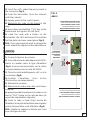
PROGRAMMAZIONE DEL RADIOCOMANDO /
PROGRAMMING THE REMOTE CONTROL
PROGRAMMATION DE LA COMMANDE RADIO
PROGRAMMIERUNG DER FUNKFERNSTEUERUNG
/ PROGRAMACION DEL MANDO A DISTANCIA
PER UTILIZZARE IL RADIOCOMANDO, ESEGUIRE LE
OPERAZIONI NEL MODO SEGUENTE
:
1) Togliere la tensione al quadro;
2) Se si utilizza la scheda radiofrequenza
AF43S, disporre il jumper secondo il tipo di
trasmettitore (fig.1), mentre sulla scheda
AF43SM, seguire le istruzioni sul relativo fo-
glio;
3) Inserire la scheda radiofrequenza «AF» sul
connettore (fig.2);
4) Codificare il trasmettitore. (Vedi relativo
foglio istruzioni);
5) Alimentare il quadro;
6)
Memorizzare la codifica sulla scheda, nel
seguente modo:
a) tenere premuto il tasto "CH1" sulla scheda
base, il led di segnalazione lampeggia;
b) con un tasto del trasmettitore s'invia il
codice, il led rimarrà acceso a segnalare
l'avvenuta memorizzazione (fig.3);
N.B.: se in seguito si vuol cambiare codice,
ripetere la sequenza descritta.
ENGLISH
ITALIANO
TO USE THE REMOTE CONTROL SYSTEM, PROCEED AS
FOLLOWS
:
1) Disconnect the power supply from the control
panel;
2) If using radio frequency board AF43S,
position the jumper according to the transmitter
type (fig.1), whereas for the AF43SM board,
carry out the instructions on the relevant
instruction sheet;
Per trasmettitori con frequenza
433.92 AM (serie TOP e serie TAM)
bisogna, sulla relativa scheda AF43S,
posizionare il jumper come illustra-
to.
On AM transmitters operating at
433.92 MHz (TOP and TAM series),
position the jumper connection on
circuit card AF43S as shown on the
sheet.
Pour les émetteurs de fréquence
433.92 AM (série TOP et série TAM)
il faut positionner le pontet sur la
carte AF43S correspondante de la
façon indiquée.
Bei Sendern mit einer Frequenz von
433.92 AM (Reihe TOP und Reihe
TAM) ist der auf der entsprechenden
Platine AF43S befindliche Jumper der
Abbildung entsprechend zu
positionieren.
Para transmisores con frecuencia
433.92 AM (serie TOP y serie TAM)
es necesario, en la tarjeta
corespondiente AF43S, colocar el
jumper como se indica en la
ilustración.
TOP TAM
FIG. 1
ABB. 1
www.came.co.uk Tech suppport : 0870 012 9000

-15-
.
A F 4 3 S / S M
M E M O R Y
A F 4 3 S / S M
FIG. 2
ABB. 2
SCHEDA BASE
MOTHERBOARD
CARTE DE BASE
BASISKARTE
TARJETA BASE
SCHEDA RADIOFREQUENZA "AF43S"
"AF43S" RADIO FREQUENCY BOARD
CARTE FREQUENCE RADIO "AF43S"
RADIOFREQUENZKARTE «AF43S»
TARJETA RADIOFRECUENCIA «AF43S»
SCHEDA RADIOFREQUENZA "AF43SM"
"AF43SM" RADIO FREQUENCY BOARD
CARTE FREQUENCE RADIO "AF43SM"
RADIOFREQUENZKARTE «AF43SM»
TARJETA RADIOFRECUENCIA «AF43SM»
FRANÇAIS
POUR UTILISER LA COMMANDE RADIO, IL FAUT:
1) Couper la tension du armoire;
2) Si on utilise la carte radiofréquence AF43S,
placer le cavalier selon le type d'émetteur
(fig.1) et suivre les instructions sur la notice
correspondante pour la carte AF43SM;
3) Placer la carte radiofréquence «AF» sur le
connecteur (fig.2);
4)Codifier l'émetteur. (Voir notice
d'instructions correspondante);
5) Alimenter le armoire;
6)
Mémoriser le code sur la carte, de la façon
suivante:
a) appuyer pendant quelques secondes sur la
touche "CH1" située sur la carte de base (le
voyant de signalisation clignote);
b) saisir le code à l'aide d'une touche de
l'émetteur, le voyant reste allumé pour signaler
que la mémorisation a été effectuée (fig.3).
N.B.: répéter la séquence décrite plus haut
pour changer de code.
3) Insert the «AF» radio frequency board in
the connector (fig.2);
4) Code the transmitter. (See the relevant
instrrction sheet);
5) Supply power to the control panel;
6)
Memorize the code on the board in this
way:
a) press down and hold the "CH1" key on the
base board, the signal LED will flash;
b) send the code with a button on the
transmitter. the LED will remain lit to indicate
that the data has been saved place (fig.3).
N.B.: if you subsequently wish to change the
code, repeat the sequence described above.
www.came.co.uk Tech suppport : 0870 012 9000

-16-
T . L .
T . C . A .
A F 4 3 S / S M
PROG
CH1
T . L .
T . C . A .
A F 4 3 S / S M
PROG
CH1
FIG. 3
ABB. 3
aa
aa
a)
bb
bb
b)
LED di segnalazione
signal LED
LED de signalisation
Anzeigeleuchtdiode
LED de señal
Scheda radiofrequenza AF
AF radiofrequency board
Carte radiofrèquence AF
Funkfrequenz-Platine AF
Tarjeta radiofrecuencia AF
VOR EINSATZ DER FUNKFERNSTEUERUNG IST:
1)Schalten Sie den Strom an der
Schalttafel ab;
2) Wenn die Radiofrequenz-Karte AF43S
verwendet wird, stellen Sie Jumper je nach
Sendertyp ein (Abb.1), wird eine Karte
vom Typ AF43SM verwendet, gehen Sie
bitte nach beiliegenden Anleitungen vor;
3) Stecken Sie die Radiofrequenzkarte
"AF" in die Steckverbindung (Abb.2);
4)Codieren Sie den Sender (siehe
entsprechende Anleitungen);
5)Schalten Sie den Strom an der
Schalttafel wieder ein;
6)
Speichern Sie die Codierung auf der
Karte. Gehen Sie dazu folgendermaßen
vor:
a) Drücken Sie die Taste "CH1" auf der
Basiskarte und halten Sie die gedrückt
(LED blinkt);
b) Mit einer Taste vom Sender wird der
Code abgeschickt. Das LED hört auf zu
blinken und bleibt an, sobald das Speichern
erfolgt ist (Abb.3)
Hinweis: Wenn Sie später den Code
ändern möchten, gehen Sie wie oben
beschrieben vor.
DEUTSCH
ESPANOL
PARA UTILIZAR EL MANDO A DISTANCIA ES PRECI-
SO:
1) Cortar la tensión al cuadro;
2) Si usa la tarjeta radiofrecuencia AF43S,
coloque el jumper de acuerdo con el tipo
de transmisor (fig.1), mientras que en la
tarjeta AF43SM, siga las instrucciones en
www.came.co.uk Tech suppport : 0870 012 9000

-17-
la hoja correspondiente;
3) Introduzca la tarjeta radiofrecuencia
"AF" en el conector (fig.2);
4) Codifique el transmisor (véase la hoja
de instrucciones correspondiente);
5) Conecte el cuadro;
6)
Memorice la codificación en la tarjeta de
la siguiente manera:
LIMITATORE DI COPPIA MOTORE /
MOTOR TORQUE LIMITER
/ LIMITEUR DE COUPLE MOTEUR
DREHMOMENTBEGRENZER DES MOTORS
/ LIMITADOR DE PAR MOTOR
Per variare la coppia motrice, spostare il
faston indicato (con filo di colore nero) su
una delle 4 posizioni; 1 min. - 4 max
To vary the motor torque, move the
indicated faston to one of the four positions:
1=min, 4=max
Pour varier le couple du moteur, déplacer
le connecteur indiqué sur l'une des 4
positions; 1 min. - 4 max.
Zur Änderung des Motor-Drehmoments
den angegebenen Faston auf eine der 4
Stellungen positionieren: 1 min. - 4 max.
ITALIANO
ENGLISH
FRANÇAIS
ESPANIOL
DEUTSCH
Para variar el par motor, desplazar el faston
indicado hasta una de las 4 posiciones; 1
mín. - 4 máx.
1
234
L2 T
L1 T
0
24
12
FU S.A C C ESSO RI1A
L1T
01224
L2T C T
a) mantenga apretada la tecla "CH1" en la
tarjeta base (el indicador luminoso de señal
parpadea);
b) con la tecla del transmisor se envía el
código, el indicador luminoso permanece
encendido para indicar que la
memorización se ha llevado a cabo (fig.3).
N.B.: si luego desea cambiar el código,
repita la secuencia descripta.
www.came.co.uk Tech suppport : 0870 012 9000
-
 1
1
-
 2
2
-
 3
3
-
 4
4
-
 5
5
-
 6
6
-
 7
7
-
 8
8
-
 9
9
-
 10
10
-
 11
11
-
 12
12
-
 13
13
-
 14
14
-
 15
15
-
 16
16
-
 17
17


CAME Z Series Benutzerhandbuch
- Typ
- Benutzerhandbuch
- Dieses Handbuch eignet sich auch für
in anderen Sprachen
- English: CAME Z Series User manual
- français: CAME Z Series Manuel utilisateur
- español: CAME Z Series Manual de usuario
- italiano: CAME Z Series Manuale utente