
Stand - Technische Änderungen, Änderungen im Design, 2017-01-27
Druckfehler und Irrtümer vorbehalten.
Technische Daten:
SKT 20-20M
Kanalzüge 2
Multituner 2 × DVB-S/S2/T/T2/C
Eingänge 2 × F Buchse
Ausgänge 1 × F-Stecker Quickfix
Stromaufnahme 16V=/1,5 A
Datenschnittstelle 1 × RJ 45
SKT 40-2xM SKT 80-2xM
Kanalzüge 4 8
Multituner 4 × DVB-S/S2/T/T2/C 8 × DVB-S/S2/T/T2/C
Eingänge 4 × F Buchse 8 × F Buchse
Ausgänge 1 × F-Stecker Quickfix 2 × F-Stecker Quickfix
Stromaufnahme 16V=/1,5 A 16V=/3 A
Datenschnittstelle 1 × RJ 45 2 × RJ 45
Alle Kassetten
Eingang
Frequenzbereich TERR | SAT 100…860 MHz | 950…2150 MHz
Eingangspegel TERR | SAT 45…85 dBµV | 43...84 dBµV/-65 … -25 dBm
LNB-Spannung 13/17 V; 22 kHz on/off; DiSEqC 1.0
Max. LNB-Strom (pro Eingang) 250 mA
Symbolrate 1,5…45 MS/s
Fehlerkorrektur automatisch
Transportstrom MPEG-2 ISO/IEC 13818 | MPEG-4 ISO/IEC 14496
Ausgang
Frequenzbereich 114…858 Mhz
Ausgangskanäle S2…K69
Modulation QPSK, QAM 16, 64, 256
FET 2k / 4k mode
FEC 1/2, 3/5, 2/3, 3/4, 4/5, 5/6
Guard Interval 1/4, 1/8, 1/16, 1/32
Norm CCIR, Australia
Ausgangspegel 80…100 dBµV
MER > 39 dB
Umgebungstemperaturbereich -10°C…+50°C
Maße ca. 72 mm × 218 mm × 129 mm
SKT 40-24M SKT 80-22M
Common Interface 4 2
Sicherheitshinweise:
4
Die Installation des Geräts und Reparaturen am Gerät sind ausschließlich
vom Fachmann unter Beachtung der geltenden VDE-Richtlinien
durchzuführen. Bei nicht fachgerechter Installation und Inbetriebnahme wird
keine Haftung übernommen.
4
Vor Öffnen des Gerätes Netzstecker ziehen bzw. Stromzuführung entfernen,
andernfalls besteht Lebensgefahr. Dies gilt auch, wenn Sie das Gerät
reinigen oder an den Anschlüssen arbeiten.
4
Sofern eine austauschbare Sicherung vorhanden ist, ist vor dem Wechsel der
Sicherung der Netzstecker zu ziehen. Defekte Sicherungen nur durch
normgerechte Sicherungen des gleichen Nennwertes ersetzen.
4
Das Gerät darf nur in trockenen Räumen betrieben werden. In feuchten
Räumen oder im Freien besteht die Gefahr von Kurzschlüssen (Achtung:
Brandgefahr) oder elektrischem Schlägen (Achtung: Lebensgefahr).
4
Um Beschädigungen am Gerät selbst oder an Peripheriegeräten
vorzubeugen, dürfen Geräte, die zur Wandmontage vorgesehen sind nur auf
flachen Oberflächen montiert werden.
4
Planen Sie den Montage- bzw. Aufstellort so, dass Sie in
Gefahrensituationen den Netzstecker leicht erreichen und aus der Steckdose
ziehen können. Wählen Sie den Montage- bzw. Aufstellort so, dass Kinder
nicht unbeaufsichtigt am Gerät und dessen Anschlüssen spielen können. Der
Montage- bzw. Aufstellort muss eine sichere Verlegung aller
angeschlossenen Kabel ermöglichen. Das Netzkabel sowie Zuführungskabel
dürfen nicht durch irgendwelche Gegenstände beschädigt oder gequetscht
werden.
4
Wählen Sie einen Montage- bzw. Aufstellungsort, an dem unter keinen
Umständen Flüssigkeiten oder Gegenstände in das Gerät gelangen können
(z. B. Kondenswasser, Dachundichtigkeiten, Gießwasser etc.)
4
Setzen Sie das Gerät niemals direkter Sonneneinstrahlung aus und
vermeiden Sie die direkte Nähe von Wärrmequellen (z. B. Heizkörper, andere
Elektrogeräte, Kamin etc.) Bei Geräten, die Kühlkörper oder Lüftungsschlitze
haben, muss daher unbedingt darauf geachtet werden, dass diese
keinesfalls abgedeckt oder verbaut werden. Sorgen Sie außerdem für eine
großzügig bemessene Luftzirkulation um das Gerät. Damit verhindern Sie
mögliche Schäden am Gerät sowie Brandgefahr durch Überhitzung. Achten
Sie unbedingt darauf, dass Kabel nicht in die Nähe von Wärmequellen (z.B.
Heizkörper, andere Elektrogeräte, Kamin etc.) kommen.
Ihr Gerät ist mit dem WEEE-Symbol markiert (Waste Electronics
and Electrical Equipment). Dies bedeutet, dass elektrische und
elektronische Komponenten nicht mit dem Restmüll entsorgt
werden dürfen. Gebrauchte elektrische und elektronische
Komponenten sind separat zu entsorgen.
WEEE Nr.
DE26869279
SKT 20-20M
SKT 40-20M | SKT 80-20M
SKT 40-24M | SKT 80-22M
Multituner | DVB-T2
Twin-/Quattro-/Octokassette
Quickstart-Anleitung
Hersteller
AXING AG
Gewerbehaus Moskau
8262 Ramsen
EWR-Kontaktadresse
Bechler GmbH
Am Rebberg 44
78239 Rielasingen

Hinweise
4
Eine detaillierte Betriebsanleitung der
Kassetten finden Sie unter www.axing.com
4
Beachten Sie die Betriebsanleitung der
Kopfstellen-Grundeinheit!
4
Beachten Sie die Betriebsanleitung des
Netzteils!
4
Bei der Montage in der Kopfstellen-
Grundeinheit wird der Potentialausgleich über
die Grundeinheit hergestellt.
4
Bei der Montage als Stand-Alone-Gerät
müssen Sie sowohl die Kassette als auch das
Netzteil gemäß EN 60728-11 am
Potentialausgleich anschließen. Verwenden Sie
den am Gerät angebrachten
Potenzialausgleichsanschluss.
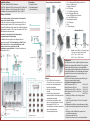
Common Interfaces
Hinweis: Jedes CAM ist nur dem dazugehörigen
Tuner zugeordnet und hat darauf Zugriff
CAM 1 - Tuner 1 | CAM 2 - Tuner 2
CAM 3 - Tuner 3 | CAM 4 - Tuner 4
CAM1
CAM2
CAM3
CAM4
CAM1
left
CAM1
right
Lieferumfang
1 × Kopfstellen-Kassette
1 × DC-Verbindungskabel
1 × Quickstart-Anleitung
1
3
3
2
1 2/4/8 × LED-Anzeige MPEG-Datenstrom Modulator
Error (rot) = Füllstand >95%
OK (grün) = Füllstand O.K.
2 4/8 × HF-Eingang
3 1/2 × RJ-45-Ethernet-Anschluss
4 4/8 × HF-Eingangs-LED Anzeige:
Orange = MPEG-Datenstrom vorhanden,
Aus = kein MPEG-Datenstrom
5 Potentialausgleichsanschluss
6 1/2 × HF-Ausgang
7 Lüfter
8 2 × DC Ein-/Ausgang
Produktbeschreibung
SKT 20-20M = Multituner - DVB-T2 Twinkassette
SKT 40-20M = Multituner - DVB-T2 Quattrokassette (SKT 40-24M mit CI)
SKT 80-20M = Multituner - QAM Octokassette (SKT 80-22M mit CI)
Die Multituner-Kassetten wandeln DVB-S/S2/T/T2/C/Cx in DVB-T2.
Montage und Anschluss
Vor der Neubestückung oder Kassettenwechsel unbedingt den
Netzstecker des Netzteils ziehen!
Die SKT kann entweder in einer Kopfstellen-Grundeinheit SKS (1) oder
Stand-Alone betrieben werden (2). Die Stromversorgung der Kassette
erfolgt mit DC-Patchkabeln über das Netzteil ((3). Bei Durchschleifung der
Spannung dürfen maximal 3 x SKT 80-2x/M oder maximal 4 x SKT 20/40-
2x/M miteinander verbunden werden.
Verwenden Sie unbedingt ein Netzteil mit genügend
Ausgangsleistung für Ihre Anwendung!
Die Multituner-Kassetten verfügen an den Eingängen über eine
Fernspeisespannung für LNB. Für den Empfang von DVB-T/T2 oder
DVB-C, müssen Sie, bevor Sie ein Antennenkabel an den HF-
Eingängen der Kassetten anschließen, die LNB-
Spannungsversorgung abschalten. Sie finden die Einstellung in der
Konfiguration in Phase 1.
Konfiguration
Die Konfiguration der Geräte erfolgt über die grafische Benutzer-
oberfläche der integrierten Webschnittstelle. Für den Zugriff auf
die Benutzeroberfläche benötigen sie einen handelsüblichen
PC/Laptop inklusive Netzwerkschnittstelle und die aktuelle Version
des installierten Webbrowsers. Für die Anbindung der Netzwerk-
schnittstelle der Kassette an den Computer benötigen sie ein
handelsübliches Netzwerkkabel.
Die SKT 80-2x hat zwei voneinander getrennte Einheiten, jede
Einheit muss separat konfiguriert werden.
Zugriff auf die Konfigurationsoberfläche:
Werks-IP-Adresse der SKT 20-2x: 192.168.0.145
Werks-IP-Adresse der SKT 40-2x: 192.168.0.145
Werks-IP-Adresse der SKT 80-2x, linke Seite: 192.168.0.145
Werks-IP-Adresse der SKT 80-2x, rechte Seite: 192.168.0.146
Subnetz-Maske: 255.255.255.0
4
Ändern Sie die IP-Adresse Ihres PC/Laptop z.B. auf
192.168.0.11
4
Geben Sie jetzt die IP-Adresse 192.168.0.145 in den Web
Browser ein.
Die Konfigurationsoberfläche ist mit einem Kennwort geschützt.
4
Geben Sie das werkseitig eingestellte Passwort Ramsen8262
ein.
4
Klicken Sie auf die Schaltfläche Enter password und
anschließend auf Open page.
4
Die Startseite wird öffnet sich.
4
Ändern Sie das Passwort nach der ersten Inbetriebnahme.
Anzeigeelemente und Anschlüsse

State of the art 2017-01-27 - Technical changes, design modifications,
errors and misprints are subject to change without prior notice.
Safety advice:
4
Installation and repairs to the equipment may only be carried out by
technicians observing the current VDE guidelines. No liability will be
assumed in the case of faulty installation and commissioning.
4
Before opening the equipment pull out the power plug or remove the
power supply, otherwise there is danger of electrocution. This is also
valid for cleaning the equipment or working on the connections.
4
Providing that a serviceable fuse exists, the power plug must be pulled
out before changing the fuse. Defective fuses may only be replaced with
standard compliant fuses that have the same nominal value.
4
The equipment may only be operated in dry rooms. In humid rooms or
outdoors there is danger of short-circuit (caution: risk of fire) or
electrocution.
4
To prevent damage to your equipment and to avoid possible peripheral
damages, the devices foreseen for wall mounting may only be installed
on a flat surface.
4
Choose the location of installation or mounting so that the power plug
can be reached and pulled out of the socket easily in case of danger.
Choose the location of installation or mounting such that children may
not play unsupervised near the equipment and its connections. The
location of installation or mounting must allow a safe installation of all
cables connected. The mains cable as well as feeder lines may not be
damaged or clamped by objects of any kind.
4
Choose the location of installation or mounting so that under no
circumstances liquids or objects can get into the equipment (e.g.
condensation, water coming from leaking roofs or flowing water, etc.).
4
Avoid exposure of the equipment to direct sunlight and to other heat
sources (e. g. radiators. other electrical devices, chimney, etc.). Devices
that are equipped with heat sinks or ventilation slots must under no
circum-stances be covered or blocked. Also ensure for a generous air
circulation around the equipment. In this way you avoid possible
damage to the equipment as well as a risk of fire caused by
overheating. Absolutely avoid that cables come near any source of heat
(e.g. radioators, other electrical devices, chimney, etc.).
WEEE Nr.
DE26869279
Your device is marked with the WEEE symbol (Waste Electronics
and Electrical Equipment). This means that the electrical and
electronic components must not be disposed of as residual waste.
Used electrical and electronic components must be disposed of
separately.
SKT 20-20M
SKT 40-20M | SKT 80-20M
SKT 40-24M | SKT 80-22M
Multituner | DVB-T2
twin/quattro/octo module
Quick start guide
Manufacturer
AXING AG
Gewerbehaus Moskau
8262 Ramsen
EWR contact adress
Bechler GmbH
Am Rebberg 44
78239 Rielasingen
Technical Data:
SKT 20-20M
Ducts 2
Multituner 2 × DVB-S/S2/T/T2/C
Inputs 2 × F Buchse
Outputs 1 × F-Stecker Quickfix
Current consumption 16V=/1,5 A
Data interface 1 × RJ 45
SKT 40-2xM SKT 80-2xM
Ducts 4 8
Multituner 4 × DVB-S/S2/T/T2/C 8 × DVB-S/S2/T/T2/C
Inputs 4 × F Buchse 8 × F Buchse
Outputs 1 × F-Stecker Quickfix 2 × F-Stecker Quickfix
Current consumption 16V=/1,5 A 16V=/3 A
Data interface 1 × RJ 45 2 × RJ 45
All modules
Input
Frequency range TERR | SAT 100…860 MHz | 950…2150 MHz
Input level TERR | SAT 45…85 dBµV | 43...84 dBµV/-65 … -25 dBm
LNB voltage 13/17 V; 22 kHz on/off; DiSEqC 1.0
Max. LNB current (per input) 250 mA
Symbol rate 1,5…45 MS/s
Error correction automatisch
Transport stream MPEG-2 ISO/IEC 13818 | MPEG-4 ISO/IEC 14496
Output
Frequency range 114…858 Mhz
Output channels S2…K69
Modulation QPSK, QAM 16, 64, 256
FET 2k / 4k mode
FEC 1/2, 3/5, 2/3, 3/4, 4/5, 5/6
Guard Interval 1/4, 1/8, 1/16, 1/32
Norm CCIR, Australia
Output level 80…100 dBµV
MER > 39 dB
Ambient temperature range -10°C…+50°C
Dimensions approx. 72 mm × 218 mm × 129 mm
SKT 40-24M SKT 80-22M
Common Interface 4 2

Product description:
SKT 20-20M = Multituner - QAM twin module
SKT 40-20M = Multituner - QAM quattro module (SKT 40-24M with CI)
SKT 80-20M = Multituner - QAM octo module (SKT 80-22M with CI)
The modules transmodulates DVB-S/S2/T/T2/C/Cx into DVB-T2.
Mounting and Installation:
Before inserting or changing a module, pull the mains plug of the
headend base unit from the socket!
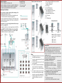
The headend modules can be operated either in a headend base units
(1) or stand-alone with the external power supply unit (2).
The module is supplied with power by DC patch cable (3). While looping
the modules through, a maximum of 3 x SKT 80-2x or 4 x SKT 20/40-2x
can be connected together.
It is imperative to use a power supply unit with sufficient output
power for your application!
At the input the modules have a remote supply voltage for the LNB. For
receiving DVB-T/T2 or DVB-C the LNB power has to be switched
off before connecting a antenna cabel to one of the HF inputs!
You will find this setting in the configuration in phase1.
Display elements and connectors
1 2/4/8 × LED indicators MPEG data stream modulator
Error (red) = Fill level >95%
OK (green) = Fill level OK
2 4/8 × HF input
3 1/2 × RJ-45 Ethernet port
4 4/8 × HF input LED indicator:
Orange = MPEG data stream present,
Off = no MPEG data stream
5 Equipotential bonding connection
6 1/2 × HF output
7 Fan
8 2 × DC input/output
Notes
4
Detailed operation instructions of the modules
are available at www.axing.com
4
Observe the operation instructions of the used
headend base unit!
4
Observe the operation instructions of the used
power supply unit!
4
If the device is mounted in the headend base
unit, the connection to the equipotential
bonding has to be done via the headend base
unit.
4
If the module is mounted external a headend
base unit the module and the power supply
unit must be connected to the equipotential
bonding according to EN 60728-11. Use the
equipotential bonding connection at the
device.
Common Interfaces
Note: Each CAM corresponds and
gets access only to according tuner.
CAM 1 - tuner 1
CAM 2 - tuner 2
CAM 3 - tuner 3
CAM 4 - tuner 4
CAM1
CAM2
CAM3
CAM4
CAM1
left
CAM1
right
Configuration:
The device is configured via the graphical user interface of the
integrated web interface. To access the user interface, you need a
standard PC/laptop with a network interface and the actual
version of the installed web browser. To connect the network
interface of the module to the computer, you need a commercially
available network cable.
The SKT 80-2x contains two separate units. Each unit has its own
web interface and its own static IP address.
Accessing the configuration interface:
Default IP address of the SKT 20-2x: 192.168.0.145
Default IP address of the SKT 40-2x: 192.168.0.145
Default IP address of the SKT 80-2x, left side: 192.168.0.145
Default IP address of the SKT 80-2x, right side: 192.168.0.146
Subnet mask: 255.255.255.0
4
Change the IP address of your PC/laptop, e.g. to 192.168.0.11.
4
Now enter the IP address 192.168.0.145 in the web browser.
The configuration screen is password-protected:
4
Enter the default password Ramsen8262.
4
Click the "Enter password" button and then the "Open page"
button.
4
This will open the start page.
4
After the first log-in, the password should be changed.
Scope of delivery:
1 × Headend module
1 × DC connection cable
1 × Quick start guide
1
3
2
3
-
 1
1
-
 2
2
-
 3
3
-
 4
4


Axing SKT 40-20M Schnellstartanleitung
- Typ
- Schnellstartanleitung
- Dieses Handbuch eignet sich auch für
in anderen Sprachen
- English: Axing SKT 40-20M Quick start guide
Verwandte Artikel
-
Axing SKT 40-20M Operation Instructions Manual
-
-
-
-
-
-
-