Cameo CLTS60RGBW Benutzerhandbuch
- Kategorie
- Flutlichter
- Typ
- Benutzerhandbuch
Dieses Handbuch eignet sich auch für

LED THEATER SPOT 40 WW / 60 RGBW
CLTS40WW / CLTS60RGBW
USER´S MANUAL
BEDIENUNGSANLEITUNG
MANUEL D`UTILISATION
MANUAL DE USUARIO
INSTRUKCJA OBSŁUGI
MANUALE D‘ USO

CONTENTS / INHALTSVERZEICHNIS / CONTENU / CONTENIDO / TREŚĆ / CONTENUTO
ENGLISH
PREVENTIVE MEASURES 3-4
INTRODUCTION 4
CONNECTIONS, CONTROLS AND INDICATORS 5-6
OPERATION CLTS40WW 6-8
OPERATION CLTS60RGBW 9-13
SETTING UP AND MOUNTING 13
WINGED BARNDOOR AND FILTER FRAME MOUNTING /
REMOVAL 13
DMX TECHNOLOGY 14
TECHNICAL SPECIFICATIONS 15
MANUFACTURER INFORMATION 15
DMX CONTROL CLTS40WW 86
DMX CONTROL CLTS60RGBW 86-88
DEUTSCH
SICHERHEITSHINWEISE 16-17
EINFÜHRUNG 17
ANSCHLÜSSE, BEDIEN- UND ANZEIGEELEMENTE 18-19
BEDIENUNG CLTS40WW 19-21
BEDIENUNG CLTS60RGBW 22-26
AUFSTELLUNG UND MONTAGE 26
FLÜGELBEGRENZER UND FILTERRAHMEN MONTIEREN /
DEMONTIEREN 26
DMX TECHNIK 27
TECHNISCHE DATEN 28
HERSTELLERERKLÄRUNGEN 29
DMX STEUERUNG CLTS40WW 86
DMX STEUERUNG CLTS60RGBW 86-88
FRANCAIS
MESURES PRÉVENTIVES 30-31
INTRODUCTION 31
CONNECTEURS, CONTRÔLES ET INDICATEURS 32-33
UTILISATION CLTS40WW 33-35
UTILISATION CLTS60RGBW 36-40
MISE EN PLACE ET MONTAGE 40
MONTAGE/DÉMONTAGE DU VOLET ET DU CADRE DE FILTRE 40
TECHNIQUE DMX 41
CARACTÉRISTIQUES TECHNIQUES 42
DÉCLARATIONS FABRICANT 43
PILOTAGE DMX CLTS40WW 86
PILOTAGE DMX CLTS60RGBW 86-88
ESPAÑOL
MEDIDAS DE SEGURIDAD 44-45
INTRODUCCIÓN 45
CONEXIONES, CONTROLES E INDICADORES 46-47
INSTRUCCIONES DE USO DEL CLTS40WW 47-49
INSTRUCCIONES DE USO DEL CLTS60RGBW 50-54
INSTALACIÓN Y MONTAJE 54
MONTAJE Y DESMONTAJE DE LA VISERA Y EL PORTAFILTROS 54
TECNOLOGÍA DMX 55
CARACTERÍSTICAS TÉCNICAS 56
DECLARACIÓN DEL FABRICANTE 57
CONTROL DMX DEL CLTS40WW 86
CONTROL DMX DEL CLTS60RGBW 86-88
POLSKI
ŚRODKI OSTROŻNOŚCI 58-59
WPROWADZENIE 59
ZŁĄCZA, ELEMENTY OBSŁUGI I WSKAŹNIKI 60-61
OBSŁUGA CLTS40WW 61-63
OBSŁUGA CLTS60RGBW 64-68
USTAWIENIE I MONTAŻ 68
MONTAŻ/DEMONTAŻ SKRZYDEŁEK I RAMY FILTRA 68
TECHNOLOGIA DMX 69
DANE TECHNICZNE 70
DEKLARACJE PRODUCENTA 71
STEROWANIE DMX CLTS40WW 86
STEROWANIE DMX CLTS60RGBW 86-88
ITALIANO
MISURE PRECAUZIONALI 72-73
INTRODUZIONE 73
CONNESSIONI, ELEMENTI DI COMANDO E VISUALIZZAZIONE 74-75
UTILIZZO CLTS40WW 75-76
UTILIZZO CLTS60RGBW 76-81
INSTALLAZIONE E MONTAGGIO 82
MONTAGGIO E SMONTAGGIO DEL DEFLETTORE AD ALETTE E DEL
TELAIO PORTAFILTRO 82
TECNOLOGIA DMX 83
DATI TECNICI 84
DICHIARAZIONI DEL FABBRICANTE 85
CONTROLLO DMX CLTS40WW 86
CONTROLLO DMX CLTS60RGBW 86-88

ITALIANOPOLSKIESPAÑOL
FRANCAISDEUTSCHENGLISH
3
DMX
ENGLISH
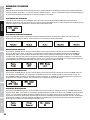
YOU‘VE MADE THE RIGHT CHOICE!
We have designed this product to operate reliably over many years. Please read this User‘s Manual carefully, so that you can begin making
optimum use of your Cameo Light product quickly. Learn more about Cameo Light on our website WWW.CAMEOLIGHT.COM.
PREVENTIVE MEASURES
1. Please read these instructions carefully.
2. Keep all information and instructions in a safe place.
3. Follow the instructions.
4. Observe all safety warnings. Never remove safety warnings or other information from the equipment.
5. Use the equipment only in the intended manner and for the intended purpose.
6. Use only sufficiently stable and compatible stands and/or mounts (for fixed installations). Make certain that wall mounts are properly installed and
secured. Make certain that the equipment is installed securely and cannot fall down.
7. During installation, observ e the applicable safety regulations for your country.
8. Never install and operate the equipment near radiators, heat registers, ovens or other sources of heat. Make certain that the equipment is
always installed so that is cooled sufficiently and cannot overheat.
9. Never place sources of ignition, e.g., burning candles, on the equipment.
10. Ventilation slits must not be blocked.
11. This appliance is designed exclusively for indoor use, do not use this equipment in the immediate vicinity of water (does not apply
to special outdoor equipment - in this case, observe the special instructions noted below). Do not expose this equipment to flammable
materials, fluids or gases.
12. Make certain that dripping or splashed water cannot enter the equipment. Do not place containers filled with liquids, such as vases or
drinking vessels, on the equipment.
13. Make certain that objects cannot fall into the device.
14. Use this equipment only with the accessories recommended and intended by the manufacturer.
15. Do not open or modify this equipment.
16. After connecting the equipment, check all cables in order to prevent damage or accidents, e.g., due to tripping hazards.
17. During transport, make certain that the equipment cannot fall down and possibly cause property damage and personal injuries.
18. If your equipment is no longer functioning properly, if fluids or objects have gotten inside the equipment or if it has been damaged in
anot her way, switch it off immediately and unplug it from the mains outlet (if it is a powered device). This equipment may only be repaired
by authorized, qualified personnel.
19. Clean the equipment using a dry cloth.
20. Comply with all applicable disposal laws in your country. During disposal of packaging, please separate plastic and paper/cardboard.
21. Plastic bags must be kept out of reach of children.
FOR EQUIPMENT THAT CONNECTS TO THE POWER MAINS:
22. CAUTION: If the power cord of the device is equipped with an earthing contact, then it must be connected to an outlet with a protective
ground. Never deactivate the protective ground of a power cord.
23. If the equipment has been exposed to strong fluctuations in temperature (for example, after transport), do not switch it on immediately.
Moisture and condensation could damage the equipment. Do not switch on the equipment until it has reached room temperature.
24. Before connecting the equipment to the power outlet, first verify that the mains voltage and frequency match the values specified on the
equipment. If the equipment has a voltage selection switch, connect the equipment to the power outlet only if the equipment values and the
mains power values match. If the included power cord or power adapter does not fit in your wall outlet, contact your electrician.
25. Do not step on the power cord. Make certain that the power cable does not become kinked, especially at the mains outlet and/or power
adapter and the equipment connector.
26. When connecting the equipment, make certain that the power cord or power adapter is always freely accessible. Always disconnect the
equipment from the power supply if the equipment is not in use or if you want to clean the equipment. Always unplug the power cord and
power adapter from the power outlet at the plug or adapter and not by pulling on the cord. Never touch the power cord and power adapter
with wet hands.
27. Whenever possible, avoid switching the equipment on and off in quick succession because otherwise this can shorten the useful life of
the equipment.
28. IMPORTANT INFORMATION: Replace fuses only with fuses of the same type and rating. If a fuse blows repeatedly, please contact an
authorised service centre.
29. To disconnect the equipment from the power mains completely, unplug the power cord or power adapter from the power outlet.
30. If your device is equipped with a Volex power connector, the mating Volex equipment connector must be unlocked before it can be re-
moved. However, this also means that the equipment can slide and fall down if the power cable is pulled, which can lead to personal injuries
and/or other damage. For this reason, always be careful when laying cables.
31. Unplug the power cord and power adapter from the power outlet if there is a risk of a lightning strike or before extended periods of disuse.
32. The device must only be installed in a voltage-free condition (disconnect the mains plug from the mains).
33. Dust and other debris inside the unit may cause damage. The unit should be regularly serviced or cleaned (no guarantee) depending on
ambient conditions (dust etc., nicotine, fog) by qualified personnel to prevent overheating and malfunction.
34. Please keep a distance of at least 0.5 m to any combustible materials.
35. Power cables to power multiple devices must have a cross-section of at least 1.5 mm². Within the EU, the cables must correspond to
H05VV-F, or similar. Suitable cables are offered by Adam Hall. With these cables, you can connect multiple devices via the power OUT con-
nection to the power IN connection of an additional device. Make sure that the total current consumption of all connected devices does not
exceed the specified value on all connected devices (label on the device). Make sure to keep power cable connections as short as possible.

4
DEUTSCHFRANCAIS
ESPAÑOL
ENGLISH
ITALIANO POLSKI
DMX
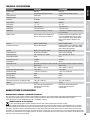
CAUTION:
To reduce the risk of electric shock, do not remove cover (or back). There are no user serviceable
parts inside. Maintenance and repairs should be exclusively carried out by qualified service
personnel.
The warning triangle with lightning symbol indicates dangerous uninsulated voltage inside the unit, which may cause an
electrical shock.
The warning triangle with exclamation mark indicates important operating and maintenance instructions.
Warning! This symbol indicates a hot surface. Certain parts of the housing can become hot during operation. After use, wait for
a cool-down period of at least 10 minutes before handling or transporting the device.
CAUTION! IMPORTANT INFORMATION ABOUT LIGHTING PRODUCTS!
1. The product has been developed for professional use in the field of event technology and is not suitable as household lighting.
2. Do not stare, even temporarily, directly into the light beam.
3. Do not look at the beam directly with optical instruments such as magnifiers.
4. Stroboscope effects may cause epileptic seizures in sensitive people! People with epilepsy should definitely avoid places where strobes are used.
INTRODUCTION
CONTROL FUNCTIONS:
1-channel, 3-channel, 5-channel DMX control (CLTS40WW)
3-channel, 4-channel, 5-channel, 7-channel and 13-channel DMX control (CLTS60RGBW)
Master / Slave mode
Standalone Functions
FEATURES CLTS40WW:
1 x high-power 40 W warm white COB LED, 15° - 38° beam angle, 1,200 Hz refresh rate, DMX-512 control, RDM enabled, manual control,
manual zoom, 16 bit dimming, master / slave operation, operating voltage 100 V - 240 V AC / 50 - 60 Hz, power consumption 40 W, mounting
bracket and winged barndoor included.
FEATURES CLTS60RGBW:
1 x high-power 60 W RGBW COB LED, RGBW colour mixing, 10° - 41° beam angle, 3,600 Hz refresh rate, DMX-512 control, RDM enabled,
manual control, manual zoom, 16 bit dimming, master / slave operation, operating voltage 100 V - 240 V AC / 50 - 60 Hz, power consumption
65 W, mounting bracket and winged barndoor included.
The spotlight is compliant with the RDM standard (Remote Device Management). This remote management system allows the status query
and configuration of RDM devices via an RDM enabled controller.

ITALIANOPOLSKIESPAÑOL
FRANCAISDEUTSCHENGLISH
5
DMX
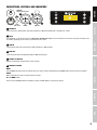
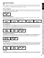
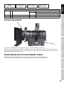
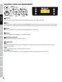
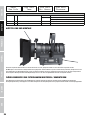
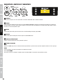
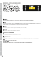
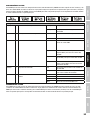
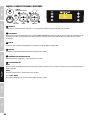
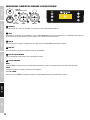
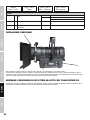
CONNECTIONS, CONTROLS AND INDICATORS
POWER IN:
100-240 V AC, 50-60 Hz
FUSE:
T1AL / 250 V DMX IN DMX OUT
MENU
ENTER
DOWN
UP
1
2
3 4
6 5 6
1
POWER IN
Firmly connected 1 meter power cable with plug (CEE 7/7). Operating voltage 100 - 240 V AC / 50 - 60 Hz.
2
FUSE
Fuse holder for 5 x 20 mm fine-wire fuses IMPORTANT INFORMATION: Replace the fuse only with a fuse of the same type and rating. If the
fuse blows repeatedly, please contact an authorised service centre.
3
DMX IN
3-pin male XLR socket for connection of a DMX controller (e.g. DMX console).
4
DMX OUT
3-pin female XLR socket for looping through the DMX control signal.
5
BACKLIT LC DISPLAY
Displays the operating mode and other system settings.
6
CONTROL BUTTONS
MENU
Pressing MENU will take you to the selection menu for system settings. Repeatedly pressing MODE takes you back to the main display.
ENTER
Makes it possible to change a value and confirm changes.
UP and DOWN buttons
Press the UP and DOWN buttons for example, to adjust the DMX address or the system settings.

6
DEUTSCHFRANCAIS
ESPAÑOL
ENGLISH
ITALIANO POLSKI
DMX
OPERATION CLTS40WW
NOTE:
When the spotlight is properly connected to the mains, the following information appears successively on the display during the startup
process: “Update Wait ...” (only for service purposes), “Welcome to Cameo”, “Fresnel” and the software version. After this step, the spot is
ready for operation and the operating mode that was previously selected is activated.
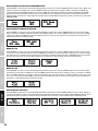
MAIN DISPLAY DMX MODE
In the upper line of the display, “DMX Addr” is displayed and in the lower line the currently set DMX start address. As soon as the DMX sig-
nal is interrupted, the display starts flashing; if the DMX signal is present again, the display stops flashing. The main display is automatically
activated if no input is made within about 30 seconds.
MAIN DISPLAY STANDALONE MODE
In the lower line of the display, the currently set operating Standalone mode is displayed (e.g. Slave, Static). The main display is automati-
cally activated if no input is made within about 30 seconds.
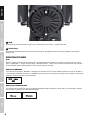
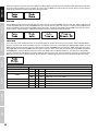
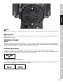
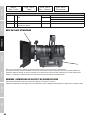
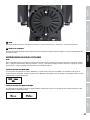
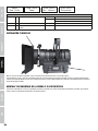
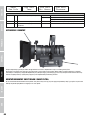
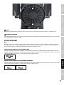
7
ZOOM
Knurled knob for adjusting the beam size (right stop = maximum beam size, left stop = minimum beam size).
8
SAFETY EYELET
Overhead installation should only be carried out by trained personnel. The spotlight must be secured with appropriate safety ropes to
prevent falling.
8
7

ITALIANOPOLSKIESPAÑOL
FRANCAISDEUTSCHENGLISH
7
DMX
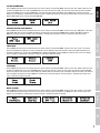
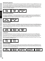
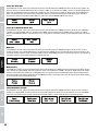
SETTING THE DMX MODE
Pressing MENU will take you to the selection menu for system settings. Using UP and DOWN, select the menu item “Mode” (lower line) and
confirm with ENTER. Now use the UP and DOWN buttons once more to select the “DMX” sub-menu item and confirm by pressing ENTER.
Using UP and DOWN, select the desired DMX mode (1CH, 3CH, 5CH) and confirm with ENTER. Press MENU twice to return to the main
display. The main display is automatically activated if no input is made within about 30 seconds. You will find tables with the channels of the
different DMX modes in this manual under DMX CONTROL.
SELECTING THE DMX START ADDRESS
Pressing MENU will take you to the selection menu for system settings. Using UP and DOWN, select the menu item “DMX Addr” and confirm
with ENTER. Now you can select the DMX start address as desired by using the UP and DOWN buttons. Confirm with ENTER and press
MENU once to return to the main display. The main display is automatically activated if no input is made within about 30 seconds.
STATIC MODE
Pressing MENU will take you to the selection menu for system settings. Using UP and DOWN, select the menu item “Static” and confirm
by pressing ENTER twice. Now you can select the brightness of the spotlight as desired with values ranging from 000 (Blackout) to 255
(maximum brightness) by using the UP and DOWN buttons. Confirm with ENTER and press MENU once more to return to the main display.
The main display is automatically activated if no input is made within about 30 seconds.
SLAVE MODE
Pressing MENU will take you to the selection menu for system settings. Using UP and DOWN, select the menu item “Mode” (lower line) and
confirm with ENTER. Now use the UP and DOWN buttons once more to select the “Slave” sub-menu item and confirm by pressing ENTER.
Connect the slave and the master unit (same model) with a DMX cable and activate the Static standalone mode on the master unit. Now the
slave unit follows the master unit. Press MENU once more to return to the main display. The main display is automatically activated if no
input is made within about 30 seconds.
DEVICE SETTINGS
Pressing MENU will take you to the selection menu for system settings. Using UP and DOWN, select the menu item “Settings” and confirm
with ENTER. You will then be taken to the sub-menu to set the sub-menu items (see table). Press MENU once more to return to the main
display. The main display is automatically activated if no input is made within about 30 seconds.

8
DEUTSCHFRANCAIS
ESPAÑOL
ENGLISH
ITALIANO POLSKI
DMX
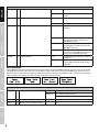
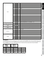
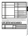
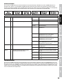
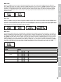
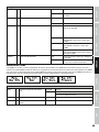
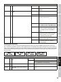
DEVICE INFORMATION
Pressing MENU will take you to the selection menu for system settings. Using UP and DOWN, select the menu item "Sys Info" and confirm
with ENTER. You will then be taken to the sub-menu to display the device information. Use the UP and DOWN panels again to select the
desired sub-menu item and then press ENTER to retrieve the information (see table). Press MENU once more to return to the main display.
The main display is automatically activated if no input is made within about 30 seconds.
Sys Info
Temp = Temperature display of the LED unit Temp LED xxC / xxF
Temp C°/F° °C (= display in degrees Celsius)
°F (= display in degrees Fahrenheit)
Op.Hours = Operating time display Hour Total Displays the total operating time in hours
Firmware = Displays the device software version Vx. xx
Settings
Display = Display lighting Backlight ON permanently on
Backlight Off deactivation after approx. 30 seconds of
inactivity
DMX Fail = Operation status with DMX signal interruption Hold last DMX command is held
Blackout activates Blackout
DimCurve = Dimmer Curve Linear
The light intensity increases linearly with the
DMX value.
Exp Adjustment of the light intensity is finer in the
lower DMX value range and coarser in the
upper DMX value range.
Log The light intensity can be adjusted coarsely in
the lower DMX value range, and finely in the
upper DMX value range.
S Curve The adjustment of the light intensity is finer
in the lower and upper DMX value ranges and
coarser in the middle DMX value range.
DimResp. = Dimmer response LED The spotlight responds abruptly to changes in
the DMX value.
Halogen The spotlight behaves in a manner similar to
that of a halogen lamp with gentle changes
in brightness.

ITALIANOPOLSKIESPAÑOL
FRANCAISDEUTSCHENGLISH
9
DMX
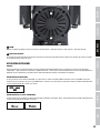
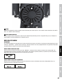
OPERATION CLTS60RGBW
NOTE:
When the spotlight is properly connected to the mains, the following information appears successively on the display during the startup
process: “Update Wait ...” (only for service purposes), “Welcome to Cameo”, “Fresnel” and the software version. After this step, the spot is
ready for operation and the operating mode that was previously selected is activated.
MAIN DISPLAY DMX MODE
In the upper line of the display, “DMX Addr” is displayed and in the lower line the currently set DMX start address. As soon as the DMX sig-
nal is interrupted, the display starts flashing; if the DMX signal is present again, the display stops flashing. The main display is automatically
activated if no input is made within about 30 seconds.
MAIN DISPLAY STANDALONE MODE
In the lower line of the display, the currently set operating Standalone mode is displayed (Sound, Slave, Auto, Static, Macro). The main
display is automatically activated if no input is made within about 30 seconds.
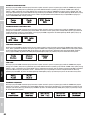
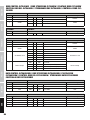
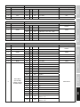
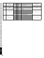
SETTING THE DMX MODE
Pressing MENU will take you to the selection menu for system settings. Using UP and DOWN, select the menu item “Mode” (lower line) and
confirm with ENTER. Now use the UP and DOWN buttons once more to select the “DMX” sub-menu item and confirm by pressing ENTER.
Using UP and DOWN, select the desired DMX mode (3CH, 4CH, 5CH, 7CH, 13CH) and confirm with ENTER. Press MENU once more to return
to the main display. The main display is automatically activated if no input is made within about 30 seconds. You will find tables with the
channels of the different DMX modes in this manual under DMX CONTROL.
SELECTING THE DMX START ADDRESS
Pressing MENU will take you to the selection menu for system settings. Using UP and DOWN, select the menu item “DMX Addr” and confirm
with ENTER. Now you can select the DMX start address as desired by using the UP and DOWN buttons. Confirm with ENTER and press
MENU once to return to the main display. The main display is automatically activated if no input is made within about 30 seconds.
MUSIC CONTROL MODE
Pressing MENU will take you to the selection menu for system settings. Using UP and DOWN, select the menu item “Mode” (lower line) and
confirm with ENTER. Now use the UP and DOWN buttons once more to select the “Sound” sub-menu item and confirm by pressing ENTER.
The Music Control mode is now activated and you can set the sensitivity to which the spotlight reacts to noise (bass pulses) as desired
using the UP and DOWN buttons (Mic Sens 00 - 99). Confirm with ENTER and press MENU once more to return to the main display. The
main display is automatically activated if no input is made within about 30 seconds.
SLAVE MODE
Pressing MENU will take you to the selection menu for system settings. Using UP and DOWN, select the menu item “Mode” (lower line) and
confirm with ENTER. Now use the UP and DOWN buttons once more to select the “Slave” sub-menu item and confirm by pressing ENTER.

10
DEUTSCHFRANCAIS
ESPAÑOL
ENGLISH
ITALIANO POLSKI
DMX
Connect the slave and the master unit (same model) with a DMX cable and activate one of the standalone modes (Sound, Auto, Static, Mac-
ro) on the master unit. Now the slave unit follows the master unit. Press MENU once more to return to the main display. The main display is
automatically activated if no input is made within about 30 seconds.
AUTO MODE
Pressing MENU will take you to the selection menu for system settings. Using UP and DOWN, select the menu item “Mode” (lower line) and
confirm with ENTER. Now use the UP and DOWN buttons once more to select the “Auto” sub-menu item, confirm by pressing ENTER twice
to adjust the program speed using UP and DOWN (Program Speed: 00 - 99). Confirm with ENTER and press MENU three times to return to
the main display. The main display is automatically activated if no input is made within about 30 seconds.
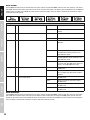
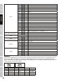
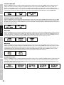
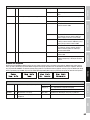
STATIC MODE
In the same way as with a DMX control unit, the static mode allows you to adjust all functions such as Dimmer, Strobe and Colour Macros
directly on the device with values from 000 to 255. Thus, an individual scene can be created without an additional DMX controller. Pressing
MENU will take you to the selection menu for system settings. Using UP and DOWN, select the menu item “Mode” (lower line) and confirm
with ENTER. Now use the UP and DOWN buttons once more to select the “Static” menu item and confirm by pressing ENTER. Using the UP
and DOWN buttons, select the desired function and confirm with ENTER. The value (Dimmer, Strobe etc., see table) of the corresponding
function can now be set from 000 to 255 and press ENTER to confirm the input. Once all of the parameters have been set as desired, press
MODE three times to return to the main display. The main display is automatically activated if no input is made within about 30 seconds.
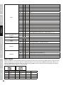
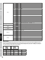
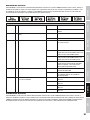
Static
Function Values
Dimmer 000 - 255 0% to 100%
Dim fine 000 - 255 0% to 100%
Strobe
000 - 005 Strobe open
006 - 255 Strobe slow -> fast <1 Hz - 20 Hz
Red 000 - 255 0% to 100%
Green 000 - 255 0% to 100%
Blue 000 - 255 0% to 100%
White 000 - 255 0% to 100%

ITALIANOPOLSKIESPAÑOL
FRANCAISDEUTSCHENGLISH
11
DMX
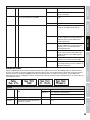
Macro
000 - 005 Colour off
006 - 013 Red
014 - 021 Amber
022 - 029 Yellow warm
030 - 037 Yellow
038 - 045 Green
046 - 053 Turquoise
054 - 061 Cyan
062 - 069 Blue
070 - 077 Lavender
078 - 085 Mauve
086 - 093 Magenta
094 - 101 Pink
102 - 109 Warm White
110 - 117 White
118 - 125 Cold White
126 - 127 Colour Jumping Stop
128 - 191 Colour Jumping Speed slow -> fast / Colour 1 -> 12
192 - 255 Colour Fading Speed slow -> fast / Colour 1 -> 12
CTC
(affects RGB and Colour Macros)
000 - 005 Off
006 - 255 7200 K - 3200 K @ Full on affects colours too
Speed
000 Off
001 - 255 Auto Program Speed slow -> fast
Sound
(if on, override everything)
000 - 005 Sound Control OFF (Mic Sensitivity)
006 - 255 Sound Control ON Low -> High (Mic Sensitivity)
DimCurve
000 - 005 No function
006 - 063 Linear Dimmer Curve
064 - 127 Exponential Dimmer Curve
128 - 191 Logarithmic Dimmer Curve
192 - 255 S-Curve Dimmer Curve
Settings
000 - 005 No function
006 - 063 Dimmer Response LED (Hold 3s)
064 - 127 Dimmer Response Halogen (Hold 3s)
128 - 191 Silent Fan on (Hold 3s)
192 - 255 Silent Fan off (Hold 5s)
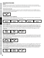
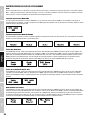
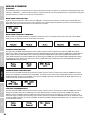
COLOUR MACROS
Pressing MENU will take you to the selection menu for system settings. Using UP and DOWN, select the menu item “Mode” (lower line) and
confirm with ENTER. Now use the UP and DOWN buttons once more to select the “Macro” menu item and confirm by pressing ENTER. Using
the UP and DOWN buttons, one of the 15 different Colour Macros can now be selected (see table). Confirm the input with ENTER.
1 Red 6 Turquoise 11 Magenta
2 Amber 7 Cyan 12 Pink
3 Yellow warm 8 Blue 13 Warm White
4 Yellow 9 Lavender 14 White
5 Green 10 Mauve 15 Cold White

12
DEUTSCHFRANCAIS
ESPAÑOL
ENGLISH
ITALIANO POLSKI
DMX
DEVICE SETTINGS
Pressing MENU will take you to the selection menu for system settings. Using UP and DOWN, select the menu item "Settings" and confirm
with ENTER. You will then be taken to the sub-menu to set the sub-menu items (Select and adjust by pressing ENTER and UP and DOWN, for
submenu items, see table). Press MENU once more to return to the main display. The main display is automatically activated if no input is
made within about 30 seconds.
DEVICE INFORMATION
Pressing MENU will take you to the selection menu for system settings. Using UP and DOWN, select the menu item "Sys Info" and confirm
with ENTER. You will then be taken to the sub-menu to display the device information. Use the UP and DOWN panels again to select the
desired sub-menu item and then press ENTER to retrieve the information (see table). Press MENU once more to return to the main display.
The main display is automatically activated if no input is made within about 30 seconds.
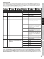
Settings
Display = Display lighting Backlight ON permanently on
Backlight Off deactivation after approx. 30 seconds of
inactivity
DMX Fail = Operation status with DMX signal interruption Hold last DMX command is held
Blackout activates Blackout
DimCurve = Dimmer Curve Linear
The light intensity increases linearly with the
DMX value.
Exp Adjustment of the light intensity is finer in the
lower DMX value range and coarser in the
upper DMX value range.
Log The light intensity can be adjusted coarsely in
the lower DMX value range, and finely in the
upper DMX value range.
S Curve The adjustment of the light intensity is finer
in the lower and upper DMX value ranges and
coarser in the middle DMX value range.
DimResp = Dimmer response LED The spotlight responds abruptly to changes in
the DMX value.
Halogen The spotlight behaves in a manner similar to
that of a halogen lamp with gentle changes in
brightness.
Calibrat = Cross-mode calibration of the colour reproduc-
tion in mixed colours.
Red Adjusting the intensity with values ranging
from 000 to 255
Green Adjusting the intensity with values ranging
from 000 to 255
Blue Adjusting the intensity with values ranging
from 000 to 255
White Adjusting the intensity with values ranging
from 000 to 255

ITALIANOPOLSKIESPAÑOL
FRANCAISDEUTSCHENGLISH
13
DMX
SETTING UP AND MOUNTING
Thanks to the integrated rubber feet, the spotlight can be placed in a suitable location on a flat surface.
Mounting on a truss is performed with the help of a suitable truss clamp (not included). Make sure that the connection to the mounting
bracket is solid, and secure the device with a suitable safety rope to the safety eyelet provided. Important Notice: Overhead installation
should only be carried out by trained personnel.
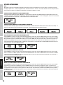
WINGED BARNDOOR AND FILTER FRAME MOUNTING / REMOVAL
To install or remove the winged barndoor and the filter frame, please press on the spring-loaded button of the
locking mechanism and fold it upwards. Place the locking mechanism in the same way in the original position.
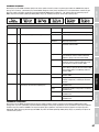
Menu
Sys Info
Sys Info
Temp
Sys Info
Op. Hours
Sys Info
Firmware
Sys Info
Temp = Temperature display of the LED unit Temp LED xxC / xxF
Temp C°/F° °C (= display in degrees Celsius)
°F (= display in degrees Fahrenheit)
Op.Hours = Operating time display Hour Total Displays the total operating time in hours
Firmware = Displays the device software version Vx. xx

14
DEUTSCHFRANCAIS
ESPAÑOL
ENGLISH
ITALIANO POLSKI
DMX
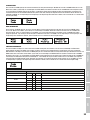
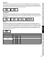
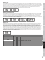
DMX TECHNOLOGY
DMX-512
DMX (Digital Multiplex) is the designation for a universal transmission protocol for
communications between corresponding devices and controllers. A DMX controller sends
DMX data to the connected DMX device(s). The DMX data is always transmitted as a serial
data stream that is forwarded from one connected device to the next via the "DMX IN" and
"DMX OUT" connectors (XLR plug-type connectors) that are found on every DMX-capable
device, provided the maximum number of devices does not exceed 32 units. The last device
in the chain needs to be equipped with a terminator (terminating resistor).
DMX CONNECTION
DMX is the common "language" via which a very wide range of types and models of equipment from various manufacturers can
be connected with one another and controlled via a central controller, provided that all of the devices and the controller are DMX
compatible. For optimum data transmission, it is necessary to keep the connecting cables between the individual devices as short as
possible. The order in which the devices are integrated in the DMX network has no influence on the addresses. Thus the device with
the DMX address 1 can be located at any position in the (serial) DMX chain: at the beginning, at the end or somewhere in the middle.
If the DMX address 1 is assigned to a device, the controller "knows" that it should send all data allocated to address 1 to this device
regardless of its position in the DMX network.
SERIAL CONNECTION OF MULTIPLE LIGHTS
1. Connect the male XLR connector (3-pin or 5-pin) of the DMX cable to the DMX output (female XLR socket) of the first DMX device
(e.g. DMX-Controller).
2. Connect the female 3-pin XLR connector of the DMX cable connected to the first projector to the DMX input (male 3-pin socket)
of the next DMX device. In the same way, connect the DMX output of this device to the DMX input of the next device and repeat until
all devices have been connected. Please note that as a rule, DMX devices are connected in series and connections cannot be shared
without active splitters. The maximum number of DMX devices in a DMX chain should not exceed 32 units.
The Adam Hall 3 STAR, 4 STAR, and 5 STAR product ranges include an extensive selection of suitable cables.
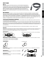
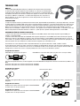
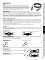
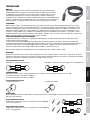
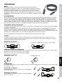
DMX CABLES
When fabricating your own cables, always observe the illustrations on this page. Never connect the shielding of the cable to the ground
contact of the plug, and always make certain that the shielding does not come into contact with the housing of the XLR plug. If the shielding
is connected to the ground, this can lead to short-circuiting and system malfunctions.
Pin Assignment
DMX cable with 3-pin XLR connectors: DMX cable with 5-pin XLR connectors (pin 4 and 5 are not used):
Shield
2
3
1
2
3
1
1
2
3
4
5
1
2
3
4
5
Shield
DMX TERMINATORS (TERMINATING RESISTORS)
To prevent system errors, the last device in a DMX chain needs to be equipped with a terminating resistor (120 ohm, 1/4 Watt).
3-pin XLR connector with a terminating resistor: K3DMXT3
5-pin XLR connector with a terminating resistor: K3DMXT5
Pin Assignment
3-pin XLR connector: 5-pin XLR connector:
2
3
1
1
2
3
4
5
DMX ADAPTER
The combination of DMX devices with 3-pin connectors and DMX devices with 5-pin connectors in a DMX chain is possible with suitable
adapters.
Pin Assignment
DMX Adapter 5-pin XLR male to 3-pin XLR female: K3DGF0020
Pins 4 and 5 are not used.
Pin Assignment
DMX Adapter 3-pin XLR male to 5-pin XLR female: K3DHM0020
Pins 4 and 5 are not used.

ITALIANOPOLSKIESPAÑOL
FRANCAISDEUTSCHENGLISH
15
DMX
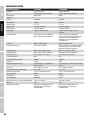
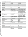
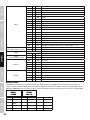
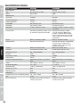
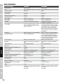
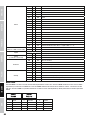
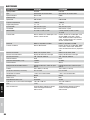
Model Name: CLTS40WW CLTS60RGBW
Product Type: LED spot LED spot
Type: Theatre Spot with Zoom Function Theatre Spot with Zoom Function
Colour Spectrum: warm white RGBW
Number of LEDs: 1 1
LED Type: 40 W COB 60 W COB
Refresh Rate: 1200 Hz 3600 Hz
Beam Angle: 15° - 38° 10° - 41°
DMX Input: 3-pin XLR male 3-pin XLR male
DMX Output: 3-pin XLR female 3-pin XLR female
DMX Mode: 1-channel, 3-channel, 5-channel 3-channel, 4-channel, 5-channel, 7-chan-
nel, 13-channel
DMX Functions: Dimmer, Dimmer Fine, Stroboscope,
Dimmer Curve, Dimmer Response
Dimmer, Dimmer fine, Stroboscope, Dim-
mer Curve, RGBW, Colour Macros, Colour
Jump, Colour Fade, Colour Temperature,
Music Control, Dimmer Response, Fan
Control
Control: DMX512, RDM enabled DMX512, RDM enabled
Standalone Functions: Dimmer, Master/Slave Dimmer, Dimmer fine, Stroboscope, RGBW,
Colour Macros, Colour Jump, Colour Fade,
Music Control, Auto Program
Controls: Mode, Enter, Up, Down, Zoom Mode, Enter, Up, Down, Zoom
Display Elements: backlit 2-line LC display backlit 2-line LC display
Operating Voltage: 100 - 240 V AC / 50 - 60 Hz 100 - 240 V AC / 50 - 60 Hz
Power Consumption: 40 W 65 W
Illuminance (@ 1 m): 18,000 lx 19,800 lx
Light Output: 1567 lm 907 lm
Power Connector: permanently attached 1m power cord with
CEE7/7 plug
permanently attached 1m power cord with
CEE7/7 plug
Fuse: T1AL / 250 V (5 x 20 mm) T1AL / 250 V (5 x 20 mm)
Temperature (during operation): 5°C to 40°C 5°C to 40°C
Relative Humidity: < 80% non-condensing < 80% non-condensing
Housing Material: metal metal
Housing Colour: black black
Housing Cooling: convection fan
Dimensions (W x H x D, excluding bracket): 145 x 205 x 240 mm 145 x 205 x 240 mm
Weight: 3.8 kg 3.8 kg
Other Features: filter frame, winged barndoor and
mounting bracket included,
manual zoom
filter frame, winged barndoor and
mounting bracket included,
manual zoom
TECHNICAL SPECIFICATIONS
MANUFACTURER´S DECLARATIONS
MANUFACTURER‘S WARRANTY & LIMITATIONS OF LIABILITY
You can find our current warranty conditions and limitations of liability at: http://www.adamhall.com/media/shop/downloads/documents/
manufacturersdeclarations.pdf. To request warranty service for a product, please contact Adam Hall GmbH, Daimler Straße 9,
61267 Neu Anspach / Email: [email protected] / +49 (0)6081 / 9419-0.
CORRECT DISPOSAL OF THIS PRODUCT
(valid in the European Union and other European countries with a differentiated waste collection system)
This symbol on the product, or on its documents indicates that the device may not be treated as household waste. This is to avoid
environmental damage or personal injury due to uncontrolled waste disposal. Please dispose of this product separately from other waste
and have it recycled to promote sustainable economic activity. Household users should contact either the retailer where they purchased
this product, or their local government office, for details on where and how they can recycle this item in an environmentally friendly manner.
Business users should contact their supplier and check the terms and conditions of the purchase contract. This product should not be mixed
with other commercial waste for disposal.

16
DEUTSCHFRANCAIS
ESPAÑOL
ENGLISH
ITALIANO POLSKI
DMX
DEUTSCH
SIE HABEN DIE RICHTIGE WAHL GETROFFEN!
Dieses Gerät wurde unter hohen Qualitätsanforderungen entwickelt und gefertigt, um viele Jahre einen reibungslosen Betrieb zu gewährleisten.
Bitte lesen Sie diese Bedienungsanleitung sorgfältig, damit Sie Ihr neues Produkt von Cameo Light schnell und optimal einsetzen können.
Weitere Informationen über Cameo Light erhalten Sie auf unserer Website WWW.CAMEOLIGHT.COM.
SICHERHEITSHINWEISE
1. Lesen Sie diese Anleitung bitte sorgfältig durch.
2. Bewahren Sie alle Informationen und Anleitungen an einem sicheren Ort auf.
3. Befolgen Sie die Anweisungen.
4. Beachten Sie alle Warnhinweise. Entfernen Sie keine Sicherheitshinweise oder andere Informationen vom Gerät.
5. Verwenden Sie das Gerät nur in der vorgesehenen Art und Weise.
6. Verwenden Sie ausschließlich stabile und passende Stative bzw. Befestigungen (bei Festinstallationen). Stellen Sie sicher, dass Wandhalterungen
ordnungsgemäß installiert und gesichert sind. Stellen Sie sicher, dass das Gerät sicher installiert ist und nicht herunterfallen kann.
7. Beachten Sie bei der Installation die für Ihr Land geltenden Sicherheitsvorschriften.
8. Installieren und betreiben Sie das Gerät nicht in der Nähe von Heizkörpern, Wärmespeichern, Öfen oder sonstigen Wärmequellen. Sorgen
Sie dafür, dass das Gerät immer so installiert ist, dass es ausreichend gekühlt wird und nicht überhitzen kann.
9. Platzieren Sie keine Zündquellen wie z.B. brennende Kerzen auf dem Gerät.
10. Lüftungsschlitze dürfen nicht blockiert werden.
11. Das Gerät wurde ausschließlich für die Verwendung in Innenräumen entwickelt, betreiben Sie das Gerät nicht in unmittelbarer Nähe von
Wasser (gilt nicht für spezielle Outdoor Geräte - beachten Sie in diesem Fall bitte die im Folgenden vermerkten Sonderhinweise). Bringen Sie
das Gerät nicht mit brennbaren Materialien, Flüssigkeiten oder Gasen in Berührung.
12. Sorgen Sie dafür, dass kein Tropf- oder Spritzwasser in das Gerät eindringen kann. Stellen Sie keine mit Flüssigkeit gefüllten Behältnisse
wie Vasen oder Trinkgefäße auf das Gerät.
13. Sorgen Sie dafür, dass keine Gegenstände in das Gerät fallen können.
14. Betreiben Sie das Gerät nur mit dem vom Hersteller empfohlenen und vorgesehenen Zubehör.
15. Öffnen Sie das Gerät nicht und verändern Sie es nicht.
16. Überprüfen Sie nach dem Anschluss des Geräts alle Kabelwege, um Schäden oder Unfälle, z. B. durch Stolperfallen zu vermeiden.
17. Achten Sie beim Transport darauf, dass das Gerät nicht herunterfallen und dabei möglicherweise Sach- und Personenschäden verursachen kann.
18. Wenn Ihr Gerät nicht mehr ordnungsgemäß funktioniert, Flüssigkeiten oder Gegenstände in das Geräteinnere gelangt sind, oder das Gerät
anderweitig beschädigt wurde, schalten Sie es sofort aus und trennen es von der Netzsteckdose (sofern es sich um ein aktives Gerät handelt).
Dieses Gerät darf nur von autorisiertem Fachpersonal repariert werden.
19. Verwenden Sie zur Reinigung des Geräts ein trockenes Tuch.
20. Beachten Sie alle in Ihrem Land geltenden Entsorgungsgesetze. Trennen Sie bei der Entsorgung der Verpackung bitte Kunststoff und
Papier bzw. Kartonagen voneinander.
21. Kunststoffbeutel müssen außer Reichweite von Kindern aufbewahrt werden.
BEI GERÄTEN MIT NETZANSCHLUSS:
22. ACHTUNG: Wenn das Netzkabel des Geräts mit einem Schutzkontakt ausgestattet ist, muss es an einer Steckdose mit Schutzleiter
angeschlossen werden. Deaktivieren Sie niemals den Schutzleiter eines Netzkabels.
23. Schalten Sie das Gerät nicht sofort ein, wenn es starken Temperaturschwankungen ausgesetzt war (beispielsweise nach dem Transport).
Feuchtigkeit und Kondensat könnten das Gerät beschädigen. Schalten Sie das Gerät erst ein, wenn es Zimmertemperatur erreicht hat.
24. Bevor Sie das Gerät an die Steckdose anschließen, prüfen Sie zuerst, ob die Spannung und die Frequenz des Stromnetzes mit den auf
dem Gerät angegebenen Werten übereinstimmen. Verfügt das Gerät über einen Spannungswahlschalter, schließen Sie das Gerät nur an die
Steckdose an, wenn die Gerätewerte mit den Werten des Stromnetzes übereinstimmen. Wenn das mitgelieferte Netzkabel bzw. der mitgelie-
ferte Netzadapter nicht in Ihre Netzsteckdose passt, wenden Sie sich an Ihren Elektriker.
25. Treten Sie nicht auf das Netzkabel. Sorgen Sie dafür, dass spannungsführende Kabel speziell an der Netzbuchse bzw. am Netzadapter
und der Gerätebuchse nicht geknickt werden.
26. Achten Sie bei der Verkabelung des Geräts immer darauf, dass das Netzkabel bzw. der Netzadapter stets frei zugänglich ist. Trennen Sie
das Gerät stets von der Stromzuführung, wenn das Gerät nicht benutzt wird, oder Sie das Gerät reinigen möchten. Ziehen Sie Netzkabel und
Netzadapter immer am Stecker bzw. am Adapter und nicht am Kabel aus der Steckdose. Berühren Sie Netzkabel und Netzadapter niemals
mit nassen Händen.
27. Schalten Sie das Gerät möglichst nicht schnell hintereinander ein und aus, da sonst die Lebensdauer des Geräts beeinträchtigt werden könnte.
28. WICHTIGER HINWEIS: Ersetzen Sie Sicherungen ausschließlich durch Sicherungen des gleichen Typs und Wertes. Sollte eine Sicherung
wiederholt auslösen, wenden Sie sich bitte an ein autorisiertes Servicezentrum.
29. Um das Gerät vollständig vom Stromnetz zu trennen, entfernen Sie das Netzkabel bzw. den Netzadapter aus der Steckdose.
30. Wenn Ihr Gerät mit einem Volex-Netzanschluss bestückt ist, muss der passende Volex-Gerätestecker entsperrt werden, bevor er entfernt
werden kann. Das bedeutet aber auch, dass das Gerät durch ein Ziehen am Netzkabel verrutschen und herunterfallen kann, wodurch Perso-
nen verletzt werden und/oder andere Schäden auftreten können. Verlegen Sie Ihre Kabel daher immer sorgfältig.
31. Entfernen Sie Netzkabel und Netzadapter aus der Steckdose bei Gefahr eines Blitzschlags oder wenn Sie das Gerät länger nicht verwenden.
32. Das Gerät darf nur im spannungsfreien Zustand (Trennung des Netzsteckers vom Stromnetz) installiert werden.
33. Staub und andere Ablagerungen im Inneren des Geräts können es beschädigen. Das Gerät sollte je nach Umgebungsbedingungen
(Staub, Nikotin, Nebel etc.) regelmäßig von qualifiziertem Fachpersonal gewartet bzw. gesäubert werden (keine Garantieleistung),
um Überhitzung und Fehlfunktionen zu vermeiden.
34. Der Abstand zu brennbaren Materialien muss mindestens 0,5 m betragen.

ITALIANOPOLSKIESPAÑOL
FRANCAISDEUTSCHENGLISH
17
DMX
35. Netzleitungen zur Spannungsversorgung mehrerer Geräte müssen mindestens 1,5 mm² Aderquerschnitt aufweisen. In der EU müssen
die Leitungen H05VV-F, oder gleichartig, entsprechen. Geeignete Leitungen werden von Adam Hall angeboten. Mit diesen Leitungen können
Sie mehrere Geräte über den Power out Anschluss mit dem Power IN Anschluss eines weiteren Gerätes verbinden. Beachten Sie, dass die
gesamte Stromaufnahme aller angeschlossenen Geräte den vorgegebenen Wert nicht überschreitet (Aufdruck auf dem Gerät). Achten Sie
darauf, Netzleitungen so kurz wie möglich zu halten.
ACHTUNG
Entfernen Sie niemals die Abdeckung, da sonst das Risiko eines elektrischen Schlages besteht. Im
Inneren des Geräts befinden sich keine Teile, die vom Bediener repariert oder gewartet werden können.
Lassen Sie Wartung und Reparaturen ausschließlich von qualifiziertem Servicepersonal durchführen.
Das gleichseitige Dreieck mit Blitzsymbol warnt vor nichtisolierten, gefährlichen Spannungen im Geräteinneren, die einen
elektrischen Schlag verursachen können.
Das gleichseitige Dreieck mit Ausrufungszeichen kennzeichnet wichtige Bedienungs- und Wartungshinweise.
Warnung! Dieses Symbol kennzeichnet heiße Oberflächen. Während des Betriebs können bestimmte Teile des Gehäuses heiß
werden. Berühren oder transportieren Sie das Gerät nach einem Einsatz erst nach einer Abkühlzeit von mindestens 10 Minuten.
VORSICHT! WICHTIGE HINWEISE IN BEZUG AUF LICHT-PRODUKTE!
1. Das Produkt ist für den professionellen Einsatz im Bereich der Veranstaltungstechnik entwickelt worden und ist nicht für die Raumbe-
leuchtung in Haushalten geeignet.
2. Blicken Sie niemals, auch nicht kurzzeitig, direkt in den Lichtstrahl.
3. Blicken Sie niemals mit optischen Geräten wie Vergrößerungsgläsern in den Lichtstrahl.
4. Stroboskopeffekte können unter Umständen bei empfindlichen Menschen epileptische Anfälle auslösen! Epilepsiekranke Menschen
sollten daher unbedingt Orte meiden, an denen Stroboskope eingesetzt werden.
EINFÜHRUNG
STEUERUNGSFUNKTIONEN:
1-Kanal, 3-Kanal, 5-Kanal DMX-Steuerung (CLTS40WW)
3-Kanal, 4-Kanal, 5-Kanal, 7-Kanal, 13-Kanal DMX-Steuerung (CLTS60RGBW)
Master / Slave Betrieb
Standalone Funktionen
EIGENSCHAFTEN CLTS40WW:
1 x High Power 40W COB Warm White LED, 15° - 38° Abstrahlwinkel, 1.200 Hz Wiederholrate, DMX-512 Steuerung, RDM enabled, manuelle
Steuerung, manueller Zoom, 16 Bit Dimming, Master- / Slave-Betrieb, Betriebsspannung 100V - 240V AC / 50 - 60Hz, Leistungsaufnahme
40W, Montagebügel und Flügelbegrenzer inklusive.
EIGENSCHAFTEN CLTS60RGBW:
1 x High Power 60W COB RGBW LED, RGBW Farbmischung, 10° - 41° Abstrahlwinkel, 3.600 Hz Wiederholrate, DMX-512 Steuerung, RDM
enabled, manuelle Steuerung, manueller Zoom, 16 Bit Dimming, Master- / Slave-Betrieb, Betriebsspannung 100V - 240V AC / 50 - 60Hz,
Leistungsaufnahme 65W, Montagebügel und Flügelbegrenzer inklusive.
Die Scheinwerfer verfügen über den RDM-Standard (Remote Device Management). Diese Gerätefernverwaltung ermöglicht die Statusabfrage
und Konfiguration von RDM-Endgeräten über einen RDM-fähigen Controller.

18
DEUTSCHFRANCAIS
ESPAÑOL
ENGLISH
ITALIANO POLSKI
DMX
ANSCHLÜSSE, BEDIEN- UND ANZEIGEELEMENTE
POWER IN:
100-240 V AC, 50-60 Hz
FUSE:
T1AL / 250 V DMX IN DMX OUT
MENU
ENTER
DOWN
UP
1
2
3 4
6 5 6
1
POWER IN
Fest verbundenes 1 Meter Netzkabel mit CEE 7/7 Stecker. Betriebsspannung 100 - 240V AC / 50 - 60Hz.
2
FUSE
Sicherungshalter für 5 x 20mm Feinsicherungen. WICHTIGER HINWEIS: Ersetzen Sie die Sicherung ausschließlich durch eine Sicherung des
gleichen Typs und mit gleichen Werten. Sollte die Sicherung wiederholt auslösen, wenden Sie sich bitte an ein autorisiertes Servicezentrum.
3
DMX IN
Männliche 3-Pol XLR-Buchse zum Anschließen eines DMX-Kontrollgeräts (z.B. DMX-Pult).
4
DMX OUT
Weibliche 3-Pol XLR-Buchse zum Weiterleiten des DMX-Steuersignals.
5
BELEUCHTETES LC-DISPLAY
Zeigt Betriebsmodus und weitere Systemeinstellungen an.
6
BEDIENTASTEN
MENU
Durch Drücken auf MENU gelangen Sie in das Auswahl-Menü für die Systemeinstellungen. Durch wiederholtes Drücken gelangen Sie
zurück zur Hauptanzeige.
ENTER
Ermöglicht einen Wert zu ändern und Wertänderungen zu bestätigen.
UP und DOWN Tasten
Betätigen Sie die UP und DOWN Tasten, um z.B. die DMX-Adresse zu ändern und Systemeinstellungen vorzunehmen.

ITALIANOPOLSKIESPAÑOL
FRANCAISDEUTSCHENGLISH
19
DMX
BEDIENUNG CLTS40WW
HINWEIS:
Sobald der Scheinwerfer korrekt am Stromnetz angeschlossen ist, werden während des Startvorgangs nacheinander verschiedene Informationen
im Display angezeigt: „Update Wait...“ (nur für Servicezwecke), „Welcome to Cameo“, „Fresnel“ und die Software-Version. Nach diesem Vorgang ist
der Scheinwerfer betriebsbereit und die Betriebsart, die zuvor angewählt war, wird aktiviert.
HAUPTANZEIGE DMX BETRIEBSART
In der oberen Zeile des Displays wird „DMX Addr“ und in der unteren Zeile die aktuell eingestellte DMX-Startadresse. Sobald das
DMX-Signal unterbrochen wird, fängt das Display an zu blinken, liegt das DMX-Signal wieder an, stoppt das Blinken. Die Hauptanzeige wird
automatisch aktiviert, wenn innerhalb von circa 30 Sekunden keine Eingabe erfolgt.
HAUPTANZEIGE STANDALONE BETRIEBSART
In der unteren Zeile des Displays wird die aktuell aktivierte Standalone Betriebsart angezeigt (Slave, Static). Die Hauptanzeige wird automatisch
aktiviert, wenn innerhalb von circa 30 Sekunden keine Eingabe erfolgt.
7
ZOOM
Rändelknopf zum Einstellen der Lichtkegelgröße (Rechtsanschlag = maximale Lichtkegelgröße, Linksanschlag = minimale Lichtkegelgröße).
8
SICHERUNGSÖSE
Überkopfmontage darf nur von dafür ausgebildetem Personal durchgeführt werden. Der Scheinwerfer ist dabei mit geeigneten Sicherungsseilen
gegen Herabfallen zu sichern.
8
7

20
DEUTSCHFRANCAIS
ESPAÑOL
ENGLISH
ITALIANO POLSKI
DMX
DMX BETRIEBSART EINSTELLEN
Durch Drücken auf MENU gelangen Sie in das Auswahl-Menü für die Systemeinstellungen. Mit Hilfe der Taster UP und DOWN wählen Sie nun den
Menü-Punkt „Mode“ (untere Zeile) aus und bestätigen mit ENTER. Wählen Sie wiederum mit Hilfe von UP und DOWN den Untermenüpunkt „DMX“
aus und bestätigen mit ENTER. Nun können Sie den gewünschten DMX-Modus mit Hilfe von UP und DOWN auswählen (1CH, 3CH, 5CH) und die
Auswahl mit ENTER bestätigen. Drücken Sie wiederholt auf MENU, um zur Hauptanzeige zurückzugelangen. Die Hauptanzeige wird automatisch
aktiviert, wenn innerhalb von circa 30 Sekunden keine Eingabe erfolgt. Tabellen mit der Kanalbelegung der verschiedenen DMX-Modi finden Sie in
dieser Anleitung unter DMX STEUERUNG.
DMX-STARTADRESSE EINSTELLEN
Durch Drücken auf MENU gelangen Sie in das Auswahl-Menü für die Systemeinstellungen. Mit Hilfe der Taster UP und DOWN wählen Sie
nun den Menü-Punkt „DMX Addr“ aus und bestätigen mit ENTER. Nun können Sie die DMX-Startadresse wunschgemäß mit Hilfe von
UP und DOWN einstellen. Bestätigen Sie die Eingabe mit ENTER und drücken 1x auf MENU, um zur Hauptanzeige zurückzugelangen. Die
Hauptanzeige wird automatisch aktiviert, wenn innerhalb von circa 30 Sekunden keine Eingabe erfolgt.
STATISCHE BETRIEBSART
Durch Drücken auf MENU gelangen Sie in das Auswahl-Menü für die Systemeinstellungen. Mit Hilfe der Taster UP und DOWN wählen Sie
den Menü-Punkt „Static“ aus und bestätigen 2x mit ENTER. Nun können Sie die Helligkeit des Scheinwerfers mit Werten von 000 (Blackout)
bis 255 (maximale Helligkeit) wunschgemäß mit Hilfe von UP und DOWN einstellen. Bestätigen Sie die Eingabe mit ENTER und drücken
wiederholt auf MENU, um zur Hauptanzeige zurückzugelangen. Die Hauptanzeige wird automatisch aktiviert, wenn innerhalb von circa 30
Sekunden keine Eingabe erfolgt.
SLAVE-BETRIEB
Durch Drücken auf MENU gelangen Sie in das Auswahl-Menü für die Systemeinstellungen. Mit Hilfe der Taster UP und DOWN wählen
Sie nun den Menü-Punkt „Mode“ (untere Zeile) aus und bestätigen mit ENTER. Wählen Sie wiederum mit Hilfe von UP und DOWN den
Untermenüpunkt „Slave“ aus und bestätigen mit ENTER.Verbinden Sie die Slave- und die Master-Einheit (gleiches Modell) mit Hilfe eines
DMX-Kabels und aktivieren Sie in der Master-Einheit die Standalone Betriebsart Static. Nun folgt die Slave-Einheit der Master-Einheit.
Drücken Sie wiederholt auf MENU, um zur Hauptanzeige zurückzugelangen. Die Hauptanzeige wird automatisch aktiviert, wenn innerhalb
von circa 30 Sekunden keine Eingabe erfolgt.
GERÄTEEINSTELLUNGEN
Durch Drücken auf MENU gelangen Sie in das Auswahl-Menü für die Systemeinstellungen. Mit Hilfe der Taster UP und DOWN wählen Sie nun
den Menü-Punkt „Settings“ aus und bestätigen mit ENTER. Daraufhin gelangen Sie in das Untermenü zum Einstellen der Untermenü-Punkte
(siehe Tabelle). Drücken Sie wiederholt auf MENU, um zur Hauptanzeige zurückzugelangen. Die Hauptanzeige wird automatisch aktiviert, wenn
innerhalb von circa 30 Sekunden keine Eingabe erfolgt.
Seite wird geladen ...
Seite wird geladen ...
Seite wird geladen ...
Seite wird geladen ...
Seite wird geladen ...
Seite wird geladen ...
Seite wird geladen ...
Seite wird geladen ...
Seite wird geladen ...
Seite wird geladen ...
Seite wird geladen ...
Seite wird geladen ...
Seite wird geladen ...
Seite wird geladen ...
Seite wird geladen ...
Seite wird geladen ...
Seite wird geladen ...
Seite wird geladen ...
Seite wird geladen ...
Seite wird geladen ...
Seite wird geladen ...
Seite wird geladen ...
Seite wird geladen ...
Seite wird geladen ...
Seite wird geladen ...
Seite wird geladen ...
Seite wird geladen ...
Seite wird geladen ...
Seite wird geladen ...
Seite wird geladen ...
Seite wird geladen ...
Seite wird geladen ...
Seite wird geladen ...
Seite wird geladen ...
Seite wird geladen ...
Seite wird geladen ...
Seite wird geladen ...
Seite wird geladen ...
Seite wird geladen ...
Seite wird geladen ...
Seite wird geladen ...
Seite wird geladen ...
Seite wird geladen ...
Seite wird geladen ...
Seite wird geladen ...
Seite wird geladen ...
Seite wird geladen ...
Seite wird geladen ...
Seite wird geladen ...
Seite wird geladen ...
Seite wird geladen ...
Seite wird geladen ...
Seite wird geladen ...
Seite wird geladen ...
Seite wird geladen ...
Seite wird geladen ...
Seite wird geladen ...
Seite wird geladen ...
Seite wird geladen ...
Seite wird geladen ...
Seite wird geladen ...
Seite wird geladen ...
Seite wird geladen ...
Seite wird geladen ...
Seite wird geladen ...
Seite wird geladen ...
Seite wird geladen ...
Seite wird geladen ...
Seite wird geladen ...
Seite wird geladen ...
Seite wird geladen ...
Seite wird geladen ...
-
 1
1
-
 2
2
-
 3
3
-
 4
4
-
 5
5
-
 6
6
-
 7
7
-
 8
8
-
 9
9
-
 10
10
-
 11
11
-
 12
12
-
 13
13
-
 14
14
-
 15
15
-
 16
16
-
 17
17
-
 18
18
-
 19
19
-
 20
20
-
 21
21
-
 22
22
-
 23
23
-
 24
24
-
 25
25
-
 26
26
-
 27
27
-
 28
28
-
 29
29
-
 30
30
-
 31
31
-
 32
32
-
 33
33
-
 34
34
-
 35
35
-
 36
36
-
 37
37
-
 38
38
-
 39
39
-
 40
40
-
 41
41
-
 42
42
-
 43
43
-
 44
44
-
 45
45
-
 46
46
-
 47
47
-
 48
48
-
 49
49
-
 50
50
-
 51
51
-
 52
52
-
 53
53
-
 54
54
-
 55
55
-
 56
56
-
 57
57
-
 58
58
-
 59
59
-
 60
60
-
 61
61
-
 62
62
-
 63
63
-
 64
64
-
 65
65
-
 66
66
-
 67
67
-
 68
68
-
 69
69
-
 70
70
-
 71
71
-
 72
72
-
 73
73
-
 74
74
-
 75
75
-
 76
76
-
 77
77
-
 78
78
-
 79
79
-
 80
80
-
 81
81
-
 82
82
-
 83
83
-
 84
84
-
 85
85
-
 86
86
-
 87
87
-
 88
88
-
 89
89
-
 90
90
-
 91
91
-
 92
92


Cameo CLTS60RGBW Benutzerhandbuch
- Kategorie
- Flutlichter
- Typ
- Benutzerhandbuch
- Dieses Handbuch eignet sich auch für
in anderen Sprachen
- français: Cameo CLTS60RGBW Manuel utilisateur
- español: Cameo CLTS60RGBW Manual de usuario
- italiano: Cameo CLTS60RGBW Manuale utente
- polski: Cameo CLTS60RGBW Instrukcja obsługi
Verwandte Artikel
-
Cameo Q-Spot 40 TW Black Benutzerhandbuch
-
Cameo Flash Matrix 250 Bedienungsanleitung
-
-
Cameo SB 6T RDM Benutzerhandbuch
-
Cameo CLMBZ100 Benutzerhandbuch
-
-
-
-
Cameo CLROOTPAR4WH Benutzerhandbuch
-
Cameo Auro Spot 200 Benutzerhandbuch
