RM FTH 740 G Instructions For Installation And Use Manual
- Typ
- Instructions For Installation And Use Manual

INSTRUCTIONS FOR INSTALLATION AND USE
DIE GEBRAUCHS-, UND INSTALLATIONSANWEISUNG
NOTICE D’INSTALLATION ET D’EMPLOI
www.rmgastro.com
GAS GRIDDLE PLATES
FTH 708 G / FTH 704 G / FTH 740 G / FTHC 704 G
FTHC 708 G / FTHC 740 G / FTHR 708 G
FTHR 780 G / FTHRC 780 G / FTR 704 G / FTR 708 G
FTR 740 G / FTR 780 G / FTRC 704 G / FTRC 740 G
FTRC 780 G / FTHC 780 G / FTHRC 708 G
FTRC 708 G / FTH 780 G / FTH 712 G / FTR 712 G /
FTHR 712 G / FTHC 712 G / FTRC 712 G /
FTHRC 712 G / FTH 7012 G / FTR 7012 G /
FTHR 7012 G / FTHC 7012 G / FTRC 7012 G /
FTHRC 7012 G
Date: 2018

CONTENT
DECLARATION OF A STANDARDS CONFORMITY 3
INSTRUCTION FOR USE 11
CLEANING AND MAINTENANCE 12
DIE NORMENÜBEREINSTIMMUNGSDEKLARATION 13
GEBRAUCHSANWEISUNG 20
REINIGUNG UND WARTUNG 21
DÉCLARATION DE CONFORMITÉ 22
MODE D´EMPLOI 29
ENTRETIEN 30

3
DECLARATION OF A STANDARDS CONFORMITY
The producer confi rms that the devices agree with 2016/426/EU, 2014/35/EU, 2014/30/EU standards, rule
nr. 22/1997 sb., 258/2000 sb, 38/2001 sb, 118/2016 sb., 117/2016 sb. and with relevant goverment orders.
Instalation must be done with respect to valid standards. Attention, the producer refuses any responsibility
in case of direct or indirect damages which are caused due to wrong instalation, incorrect intervention or
modifi cation, insuffi cient maintenance, incorrect use and also possibly caused by other reasons presented by
items in sale conditions. This appliance is set only for skilled use and must be operated by qualifi ed persons
only. Parts set and secured by the producer or accredited person must not be rebuilt by user.
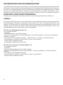
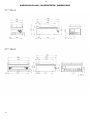
TECHNICAL DATA
Label with technical data is placed on the back side of the device. Study the electrical diagram of connection
and all following information before instalation.
3

4
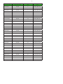
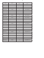
Type of product Burner performance
Power
(kW)
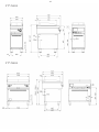
Dimmensions
(mm)
FTH- 704 G 1x 7Kw 7 400 x 758 x 378
FTH- 708 G 2x 7Kw 14 800 x 758 x 378
FTH- 740 G 1x 7Kw 7 400 x 758 x 957
FTH- 780 G 2x 7Kw 14 800 x 758 x 957
FTH- C-704 G 1x 7Kw 7 400 x 758 x 378
FTH- C-708 G 2x 7Kw 14 800 x 758 x 378
FTH- C-740 G 1x 7Kw 7 400 x 758 x 957
FTH- C-780 G 2x 7Kw 14 800 x 758 x 957
FTHR- 708 G 2x 7Kw 14 800 x 758 x 378
FTHR- 780 G 2x 7Kw 14 800 x 758 x 957
FTHR- C-708 G 2x 7Kw 14 800 x 758 x 378
FTHR- C-780 G 2x 7Kw 14 800 x 758 x 957
FTR- 704 G 1x 7Kw 7 400 x 758 x 378
FTR- 708 G 2x 7Kw 14 800 x 758 x 378
FTR- 740 G 1x 7Kw 7 400 x 758 x 957
FTR- 780 G 2x 7Kw 14 800 x 758 x 957
FTR- C-704 G 1x 7Kw 7 400 x 758 x 378
FTR- C-708 G 2x 7Kw 14 800 x 758 x 378
FTR- C-740 G 1x 7Kw 7 400 x 758 x 957
FTR- C-780 G 2x 7Kw 14 800 x 758 x 957
FTH 712 G 3X 7kW 21 1200 x 370 x 730
FTR 712 G 3X 7kW 21 1200 x 370 x 730
FTHR 712 G 3X 7kW 21 1200 x 370 x 730
FTHC 712 G 3X 7kW 21 1200 x 370 x 730
FTRC 712 G 3X 7kW 21 1200 x 370 x 730
FTHRC 712 G 3X 7kW 21 1200 x 370 x 730
FTH 7012 G 3X 7kW 21 1200 x 960 x 730
FTR 7012 G 3X 7kW 21 1200 x 960 x 730
FTHR 7012 G 3X 7kW 21 1200 x 960 x 730
FTHC 7012 G 3X 7kW 21 1200 x 960 x 730
FTRC 7012 G 3X 7kW 21 1200 x 960 x 730
FTHRC 7012 G 3X 7kW 21 1200 x 960 x 730

5
PLACEMENT
The device must be instalated in well ventilated room what is necessary for regulation of the function of the
device (technician must go by valid standard (EN....). If the device is situated close to the wall or if it is in
contact with the furniture walls, these walls must resist the temperatures ranging to 90°C. Instalation, setting,
putting into operation must be done by qualifi ed person who is competent for this and according to the valid
standards.
Wrap up the device and check whether it was not damaged during transport. Settle the device on horizontal
surface (max imbalance 2°).Settle the device under the fumehood to eliminate water steam and bad smell.
The device can be instalated separately or in a set with devices of our production. Min. distance 10 cm
from other subjects must be kept.It is also necessary to prevent our product from contact with combustible
materials. In this case you must make corresponding changes to secure heat izolation of combustible parts.
Safety measures from the standpoint of the fi re protection according to EN 061008čl. 21:
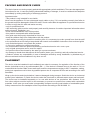
PACKING AND DEVICE CHECK
The device leaves our stocks properly packed with appropriate symbols and labels. There are also appropriate
instructions for use. In case the packing shows bad handling or damage, it must be reclaimed at transporter
immediately by writing and signing of a damage protocol.
Important notice:
-This product is only intended for use inside.
Never use the appliance if it has a damaged supply cable or plug, if it is not working correctly, has fallen to
the ground and been damaged or fallen into water. In such cases take the appliance to a professional service
in order to verify that it is safe and works correctly.
• only for proff esional use
• this instructing guide must be read properly and carefully because it contains important information about
safety elements, installation, use
• these recommendations refer to this product
• this product corresponds with valid standards
• this guide must be properly deposited for future use
• keep the children away from manipulation with the product
• when selling or moving the product to another place it is necessary top make yourself sure that the staff
or the professional service has got acquainted with control and installation instructions from enclosed guide
• only authorised person can operate the product
• it can not be switched on without supervision
• we recommend to have the product checked by professional service min. once a year
• only original spare parts can be used for repairs
• the product can not be cleaned by the water jet or pressure shower
• by damage or break down disconnect all the feeders (water, gas, electricity) and call professional service
• producer refuses any responsibility in case of damages caused by wrong installation, by disobserving of
above mentioned recommendations or by other use etc.
5

6
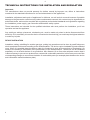
TECHNICAL INSTRUCTIONS FOR INSTALATION AND REGULATION
Important:
The manufacturer does not provide warranty for defects caused by improper use, failure to instructions
contained in the attached instructions for use and mistreatment of the appliances.
Installation, adjustment and repair of appliances for kitchens, as well as their removal because of possible
damage to the gas can be carried out only under a maintenance contract, this contract may be signed with an
authorized dealer, and must be complied with regulations and technical standards and regulations regarding
the installation, power supply, gas connection and health & safety system.
These instructions are intended for the qualifi ed technician who must perform the installation, put it into
operation and test the appliance.
Any activity as settings, placement, rebalancing etc, must be made only when is device disconnected from
electricity. If it is necessary to have the device connected to the electricity you must keep the highest attention
to avoid any injuries.
DEVICE INSTALATION
Instalation, setting, rebuilding for another gas type, putting into operation must be done by qualifi ed person
whois competent for this and according to the valid standards. The device can be instalated in good ventilated
room. When it is possible place the device under the fumehood to suck off the products of combustion. Air
needy to the burning is 2m/3/h/kW ot the performance of the instaled device. The device can be instalated
separately or in a set with devices of our production. Min. distance 10 cm from other subjects must be kept.It
is also necessary to prevent our product from contact with combustible materials. In this case you must make
corresponding changes to secure heat izolation of combustible parts (for example:place between the device
and combustible material azbestos plate).
6

7
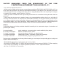
SAFETY MEASURES FROM THE STANDPOINT OF THE FIRE
PROTECTION ACCORDING TO EN 061008 ČL. 21
• only adults can operate the device
• device must be safely used in common surroundings according to EN 332000-4-462; EN 332000-4-42. You
must switch the gas device off under the circumstances leading: to the danger of the temporary rise of the
combustion gas or steam or during works when there is a big possibilityof rise ot the temporary fi re danger
or explosion (for example: to stick linoleum, PVC etc.).
• before you start to instal the device you must get the licence for connection to the gas feeder from the
gasworks
• device must be placed so as to stand or hang on the noncombustible surface which is on each side 10
cm larger than the device. No subjects from combustible materials can be placed directly on the device
or in distance which is shorter than safety distance (the shortestdistance is 50 cm in the direction of the
heat emission and 10 cm in other directions).- safety distances from various materials of diff erent degree of
combustion and information about the degree of comb. of common building materials - see chart:
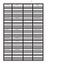
Chart:
Combustion degree of building materials classifi ed according to the combustion degree of materials and
products (EN 730823)
A noncombustible granit, sandstone, concretes,bricks, ceramic wallfacing tiles, plaster
B uneasily combustible akumine, heraklite, lihnos, itavere
C1 hardly combustible leafy wood, plywood, sirkoklit, rare paper formica
C2 middle combustible fi breboards, solodure, cork boards, rubber,fl oor-coverings
C3 easily combustible wood-fi breboards, polystyrene,polyurethane, PVC
Devices must be instalated in a safe way. When instaling you must respect corresponding project, safety and
hygienic orders according to:
• EN 061008 fi re protection of local devices and sources of heat
• EN 332000 (33 2000-4-482; 33 2000-4-42) surrounding for electric devices ČSN EN 1775 Gas supplying
• Gas fi ttings in the buildings - the highest operational pressure < 5 bar - operation demands
• § 10 law nr. 185/2001 Sb. about waste

8
PIPE FOR GAS CONNECTION
It must fi rst determine if the appliance is made for the same type of gas that will be used and thus conforms
to the indications on the label the type of gas to be used.
The conversion of gas pan to another type of gas you need to check if it corresponds to the type of gas
bearing, which is recommended in this guide.
Connecting the appliance to the gas distribution must be towable to a steel or copper tube complying with
applicable national requirements. This must be controlled on regular basis and changed if needed. Every
appliance must be equipped with shut-off valve and quick shut-off valve. Quick shut-off valve must be freely
accessible and within reach of the device. After installation, is necessary to check whether there is a gas leak.
To fi nd a gas leak you can use soapy water or spray for gas leak detection.
Do not use corrosive substances!! All our appliances are carefully controlled. Gas type, pressure and of the
categories listed named on the technical information plate.
Liquid gas connection:
Pressure for liquid gas connection must be 28 or 30 mbar for propane/butane and 37 mbar for propane. It
is necessary to check the technical label ,gauge the pressure and check the parameters of the nozzle is
installed with the required parameters of the nozzle according to the manufacturer‘s. If the pressure is lower
than 25mbar or higher than 37 mbar, THE APPLIANCE SHALL NOT TO BE CONNECTED.
Gas Connection:
Pressure for methane connection must be 18 or 20 mbar. It is necessary to check the technical label ,gauge
the pressure and check the parameters of the nozzle is installed with the required parameters of the nozzle
according to the manufacturer‘s. If the gas pressure is lower than 15mbar or higher than 22,5 mbar, THE
APPLIANCE SHALL NOT TO BE CONNECTED.
8

9
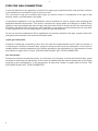
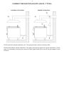
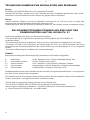
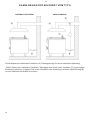
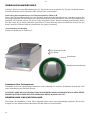
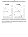
Outlet hood with natural extraction (A). Flue gas provides a natural chimney draft.
Outlet hood without natural extraction. Flue gas is secured by a fan (D) (forced extraction). In this
case, it is necessary to secure the connection with a gas feeder (B) to turn off the gas supply in case
of failure.
NATURAL EXTRACTION FORCED EXTRACTION
CHIMNEY DESIGN FOR AN APPLIANCE –TYPE A

10
10
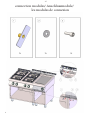
CHECK THE GAS TYPE THE DEVICE IS ADJUSTED FOR
Our appliances are certifi ed and regulated the natural gas (see technical plate). Conversion or adaptation to
a diff erent type of gas must be performed by authorized personnel. Nozzles for diff erent types of gas are in a
bag provided with the gas cooker and are marked in hundredths of mm (table of technical data pipes).
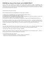
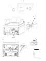
Nozzle replacement and pressure adjustment
Proceed as follows when replacing the main burner nozzle:
1) remove the control buttons from the front panel (fi g.1, note 1)
2) disassemble the front panel (fi g.1, note 2)
3) According to picture (fi g. 2) unscrew the nozzle from the main burner and replace with nozzles according
to table „TECHNICAL DATA“
4) Adjust the air intake for the relevant gas according to table „TECHNICAL DATA“
Adjust the pilot burner by loosening the safety nut (pct.3, note 1) with a spanner, then unscrew the pilot burner
nozzle and replace with a nozzle for the relevant gas according to the table. Tighten the nozzle cover with a
spanner.
Important:
After what was done adjusting the appliance to another type of gas, it is necessary to change the gas
indicated on the technical plate located in a visible location on the back of the device.

11
1
2
3
4
unmout
jet
unmout
jet

12
12
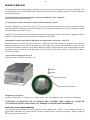
INSTRUCTION FOR USE
Attention!
When the hot-plate smokes after the fi rst switching it on it is necessary to leave the device on at least for an
hour until the smoke disappears.
• Ignition of the main burner and regulation of the temperature: pictures A,B
Turn the regulation knob (2) into position „ignition of the main burner“ and then press it down and hold it.
Press down the piezo knob of the ignitor several times (1) until the main burner burns. The fl ame is visible
through the slot in the front panel. After ignition of the burner hold the knob (2) pressed several seconds till
the thermofuse gets hot. Then release the button. If the fl ame goes out repeat the whole process once more.
• How to switch the whole device off : picture A,B
Turn the knob (2) into position“0“.
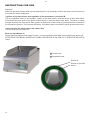
Bowl for superfl uous oil
Check this bowl regularly and empty it in time. You must clean the bowl after each switching the device off .
ATTENTION! THIS BOWL CAN BE HOT WHEN THE DEVICE IS ON. EMPTY IT WHEN THE DEVICE IS
COLD.
1
2
Piezzo knob
Regulation knob
Switch off
Switch on the main
burner
1
2
3

13
CLEANING AND MAINTENANCE
It is recommended to have the device checked by the professional service min. once a year. All interventions
must be done by qualifi ed person who is competent for this.
ATTENTION!
The device cannot be cleaned by direct or pressure water. Clean it daily. Daily maintenance keeps longer
useful life and effi ciency of the device. Before cleaning make sure to have disconnected the device from
electricity. Always switch off the main feeder to the device. Stain-less parts wash with moist cleaning cloth
and detergent without groove parts than wash it with clean water and dry it by the cloth. Do not use abrasive
and corrosive detergents.
WHAT TO DO IN CASE OF BREAK-DOWN
Switch off the electric feeder and call seller´s proff esional service.
INDICATION:
Guarentee does not cover all consumption parts succumable to common wear (rubber seals, bulbs, glas and
plastic parts etc.). The guarantee does not refer to the devices which were not instaled in correspondance with
instructions - by qualifi ed worker, in confi rmity with standards and when somebody handled incompetently the
device (interventions into inner equipment) or the device was operated by nonqualifi ed staff or at variance
with instructions for use. Guarantee does not also cover the damages caused due to infl uance of nature or
other outer intervention.
Point for cleaning steel-alloy plate:
• Heat up the device
• Turn of the device
• The plate pull off with scraper
• Apply water to chemistry (RM gril) and clean the plate from residual dirt and sediment
• Apply pure water (The solution is with vinegar or lemon)
• Pull off the water and than to dry the plate with rag
• Turn on the device up to 70 °C and from the plate let evaporate residual humidity
• To smear the grill areas with vegetable oil
Point for cleaning chrome plate:
• Heat up the device
• Turn of the device
• The plate pull off with plastic scraper
• Apply water with a saponate and clean the plate with a sponge
• Apply pure water
• Pull off the water and than to dry the plate with rag
• Turn on the device up to 70 °C and from the plate let evaporate residual humidity

14
DIE NORMENÜBEREINSTIMMUNGSDEKLARATION
Der Produzent erklärt, daß die Geräte in einer Übereinstimmung mit den Vorschriften der
2016/426/EU, 2014/35/EU, 2014/30/EU dem Gesetz Nr. 22/1997 sb., nr. 258/2000 sb., nr. 38/2001 sb. der
Sammlung und zugehörigen Regierungsverordnungen stehen. Die Installation muss mit der Absicht auf
geltende Normen durchgeführt werden. Vorsicht, im Falle einer direkten oder indirekten Beschädigung,
die sich auf falsche Installation, unrichtigen Eingriff oder Anpassungen, ungenügende Instandshaltung,
unrichtige Verwendung beziehen, und welche eventuell durch andere Ursachen, als in Punkten der
Verkaufsbedingungen angeführt ist, so verzichtet der Importeur auf jegliche Verantwortung. Dieses Gerät ist
nur für fachliche Verwendung bestimmt und muß durch qualifi zierte Person bedient werden. Teile, die nach
der Einstellung durch den Hersteller oder durch befugte Person gesichert wurden, dürfen vom Benutzer
keineswegs umgestellt werden.
DIE TECHNISCHEN DATEN
Das Schild mit technischen Angaben ist auf der Rückseite des Gerätes angebracht. Studieren sie vor der
Installation das elektrische Schema der Einschließung und alle folgende Informationen durch.
14

15
Modell Burner
ANSCHLUSSWERT
(kW)
PLATTEABMESSUNG
(mm)
FTH- 704 G 1x 7Kw 7 400 x 758 x 378
FTH- 708 G 2x 7Kw 14 800 x 758 x 378
FTH- 740 G 1x 7Kw 7 400 x 758 x 957
FTH- 780 G 2x 7Kw 14 800 x 758 x 957
FTH- C-704 G 1x 7Kw 7 400 x 758 x 378
FTH- C-708 G 2x 7Kw 14 800 x 758 x 378
FTH- C-740 G 1x 7Kw 7 400 x 758 x 957
FTH- C-780 G 2x 7Kw 14 800 x 758 x 957
FTHR- 708 G 2x 7Kw 14 800 x 758 x 378
FTHR- 780 G 2x 7Kw 14 800 x 758 x 957
FTHR- C-708 G 2x 7Kw 14 800 x 758 x 378
FTHR- C-780 G 2x 7Kw 14 800 x 758 x 957
FTR- 704 G 1x 7Kw 7 400 x 758 x 378
FTR- 708 G 2x 7Kw 14 800 x 758 x 378
FTR- 740 G 1x 7Kw 7 400 x 758 x 957
FTR- 780 G 2x 7Kw 14 800 x 758 x 957
FTR- C-704 G 1x 7Kw 7 400 x 758 x 378
FTR- C-708 G 2x 7Kw 14 800 x 758 x 378
FTR- C-740 G 1x 7Kw 7 400 x 758 x 957
FTR- C-780 G 2x 7Kw 14 800 x 758 x 957
FTH 712 G 3X 7kW 21 1200 x 370 x 730
FTR 712 G 3X 7kW 21 1200 x 370 x 730
FTHR 712 G 3X 7kW 21 1200 x 370 x 730
FTHC 712 G 3X 7kW 21 1200 x 370 x 730
FTRC 712 G 3X 7kW 21 1200 x 370 x 730
FTHRC 712 G 3X 7kW 21 1200 x 370 x 730
FTH 7012 G 3X 7kW 21 1200 x 960 x 730
FTR 7012 G 3X 7kW 21 1200 x 960 x 730
FTHR 7012 G 3X 7kW 21 1200 x 960 x 730
FTHC 7012 G 3X 7kW 21 1200 x 960 x 730
FTRC 7012 G 3X 7kW 21 1200 x 960 x 730
FTHRC 7012 G 3X 7kW 21 1200 x 960 x 730

16
DIE VERPACKUNGS-, UND VORRICHTUNGSKONTROLLE
Die Vorrichtung verlässt unsere Lager in ordentlicher Verpackung, auf deren die entsprechenden Symbole
und Bezeichnungen stehen. In der Verpackung befi ndet sich entsprechende Bedienungsanweisung. Falls die
Verpackung eine schlechte Behandlung oder Anzeichen der Beschädigungen vorweist, muß dieses sofort
beim Transporteur reklamiert werden und zwar durch Unterzeichnung eines Schadensprotokolles.
Wichtige Hinweise
-Das Erzeugnis ist nur zur Verwendung im Innenraum bestimmt.
Verwenden Sie den Verbraucher nie, wenn die Speisezuleitung oder der Stecker beschädigt sind, das Gerät
nicht richtig arbeitet, ist auf den Boden gefallen und hat sich beschädigt oder ist ins Wasser gefallen. Bringen
Sie in solchen Fällen den Verbraucher zu einem Fach-Kundendienst zur Überprüfung seiner Sicherheit und
richtiger Funktion.
• Nur für professionellen Verbrauch geeignet
• Diese Bediennungsanleitung muss ordentlich und bedächtig gelesen werden, weil sie wichtige Informationen
über Sicherheitsmerkmale, Installation und Anwendung beinhaltet
• Diese Empfehlungen beziehen auf diesen Produkt
• Der Produkt entspricht geltenden Normen
• Diese Anleitung muß ordentlich für die zukünftige Verwendung hinterlegt werden
• Hindern Sie den Kinder an Vorrichtungsmanipulation
• Beim Verkauf oder Verlegung ist es notwendig sich zu überzeugen, daß die Bedienstperson oder Fachservis
sich mit der Behherrschung und Installationsanweisung in beiligender Anleitung, anvertraut gemacht haben.
• Das Produkt darf nur eingeschulte Bedienung bedienen
• Das Produkt darf nicht ohne Aufsicht ins Betrieb gesetzt sein
• Es ist empfohlen, minimal einmal pro Jahr eine Fachkontrolle durchführen zu lassen
• Bei eventueller Reparatur der Teilenumtauschungen müssen ausschließlich Originalteile angewendet
werden
• Das Produkt darf nicht durch einen Wasserstrahl oder Druckbrause gereinigt werden
• Schalten Sie alle Leitungen (Wasser, Elektrizität, Gas) bei einer Störung oder beim schlechten Lauf aus und
rufen Sie authorisierten Service an
• Der Hersteller verzichtet auf jegliche Verantwortung bei Störungen, die durch fehlerhafte Installation,
Nichteinhaltung o.a. Empfehlungen, andere Verwendung u.ä, verursacht wurden
DIE PLATZIERUNG
Es ist unbedingt notwendig, zu der Regulation der Gerätetätigkeit, daß das Milieu - der Küche -, wo das Gerät
installiert wird, sehr gut belüftbar ist (im Hinblick darauf: sei der Techniker sich mit geltenden Normen (EN)
richtet). Wenn die Einrichtung so plaziert wird, daß sie im Mobiliarwandkontakt stehen wird, so müssen diese
einer Temperatur von 90°C wiederstehen. Die Installation, Herrichtung, Inbetriebsnahme müssen durch
qualifi zierte Person, die zu solchen Vorkehrungen eine Befugnis hat und dies laut geltenden Normen nach,
durchgeführt werden.
Packen Sie das Gerät aus und kontrollieren Sie , ob sich das Gerät während des Transportes nicht beschädigt
hat. Platzieren Sie das Gerät auf eine waagrechte Fläche (maximalle Unebenheit bis 2°). Stellen Sie das
Gerät unter den Haubenabzug, damit Sie die Wasserdämpfe und den Geruch eliminieren. Das Gerät kann
selbständig oder in einer Reihe mit Geräten unserer Herrstellung installiert werden. Es ist notwendig die
minimale Entfernung von 10 cm zu anderen Gegenständen einzuhalten, so dass die Wärmeisollierung der
brennbaren Teilen gewährleistet wird.
Das Gerät kann selbständig oder in einer Reihe mit Geräten unserer Herrstellung installiert werden. Es
ist notwendig die minimale Entfernung von 10 cm zu anderen Gegenständen einzuhalten, so dass die
Wärmeisollierung der brennbaren Teilen gewährleistet wird.
16
DIE SICHERHEITSVORRICHTUNGEN AUS DER SICHT DES
FEUERSCHUTZES LAUT EN. 061008 ČL. 21
Die Einrichtungsbedienung dürfen nur Erwachsene ausführen
• Das Gerät darf sicher in gewöhnlicher Umgebung laut EN 332000-4-482; EN 332000-4-42
verwendet werden.
• Es ist notwendig das Gerät so platzieren, daß es auf einer unbrennbaren Grundlage steht oder hängt.
• Es dürfen, auf und in eine Entfernung, die kleinerermase als sicher vom Gerät bezeichnet wird, keine
Gegenstände aus brennbaren Materilien (die kleinste Entfernung vom Brennbarem ist 10 cm) aufgestellt
werden.
• Die sicheren Entfernungen von Massen der einzelnen Brenngra
Tabelle:
Baumassefeuerbrenngrad ins Brenngrad (EN) der Massen und Produkte eingegliedert
A Unbrennbar Granit, Sandstein, beton, Ziegel, Keramikbekleidung, Putz
B nicht einfach brennbar Akumin, Heraklit, Lihnos, Itaver
C1 schwer brennbar Holz, Laubbaum, Furnier Sirkoklit, Festpapier, Umakart
C2 mittel brennbar Holzspanplatten, Solodur, Korkplatten, Hartgummi, Bodenbeläge
C3 leicht brennbar Holzfaserplatten, Polystyren, Polyureten, PVC
Die Bedarfsartikel müssen sicher installiert werden und sind mit regulierenbaren Beinchen - zur Ausgleichen
der Höhe und der Unebenheiten eingestattet.
Die Geräte müssen in einer sicheren Weise installiert werden. Bei der Installation müssen weiter betreff ende
Projekt-, Sicherheits-, und Hygienevorschriften respektiert werden.
• EN 06 1008 Feuerschutz der örtlichen Geräte und der Wärmquellen
• EN 33 2000 (
33 2000-4-482; 33 2000-4-42) Umgebung für elektrische Geräte
Gasversorgung -Gasleitunge in Gebäuden - Höchste Verkehrsdruck ≤ 5 BarVerkehrsansprüche,
• § 10 des Gesetzes Nr.185/2001 Sb., der Abfälle betriff t.

17
TECHNISCHE HINWEISE ZUR INSTALLATION UND REGELUNG
Wichtig:
Zur Benützung AUSSCHLIEßLICH nur für spezialisierte Techniker
Instruktionen, die folgen, wenden sich an den Techniker, der für die Installation qualifi ziert ist, damit er alle
Operationen mit der korrektesten Weise und laut der gültigen Normen durchführt.
Wichtig
Jeweils irgendeine Tätigkeit, die mit der Regulation verbunden ist u.ä, muß nur mit der aus dem Netz
ausgezogenen und abgeschalteten Einrichtung vollgezogen sein.
Solange das Gerät unter der Spannung notwendig zu halten ist, eine höchste Vorsicht zu beachten vorliegt.
DIE SICHERHEITSVORRICHTUNGEN AUS DER SICHT DES
FEUERSCHUTZES LAUT EN. 061008 ČL. 21
Die Einrichtungsbedienung dürfen nur Erwachsene ausführen
• Das Gerät darf sicher in gewöhnlicher Umgebung laut EN 332000-4-482; EN 332000-4-42
verwendet werden.
• Es ist notwendig das Gerät so platzieren, daß es auf einer unbrennbaren Grundlage steht oder hängt.
• Es dürfen, auf und in eine Entfernung, die kleinerermase als sicher vom Gerät bezeichnet wird, keine
Gegenstände aus brennbaren Materilien (die kleinste Entfernung vom Brennbarem ist 10 cm) aufgestellt
werden.
• Die sicheren Entfernungen von Massen der einzelnen Brenngra
Tabelle:
Baumassefeuerbrenngrad ins Brenngrad (EN) der Massen und Produkte eingegliedert
A Unbrennbar Granit, Sandstein, beton, Ziegel, Keramikbekleidung, Putz
B nicht einfach brennbar Akumin, Heraklit, Lihnos, Itaver
C1 schwer brennbar Holz, Laubbaum, Furnier Sirkoklit, Festpapier, Umakart
C2 mittel brennbar Holzspanplatten, Solodur, Korkplatten, Hartgummi, Bodenbeläge
C3 leicht brennbar Holzfaserplatten, Polystyren, Polyureten, PVC
Die Bedarfsartikel müssen sicher installiert werden und sind mit regulierenbaren Beinchen - zur Ausgleichen
der Höhe und der Unebenheiten eingestattet.
Die Geräte müssen in einer sicheren Weise installiert werden. Bei der Installation müssen weiter betreff ende
Projekt-, Sicherheits-, und Hygienevorschriften respektiert werden.
• EN 06 1008 Feuerschutz der örtlichen Geräte und der Wärmquellen
• EN 33 2000 (
33 2000-4-482; 33 2000-4-42) Umgebung für elektrische Geräte
Gasversorgung -Gasleitunge in Gebäuden - Höchste Verkehrsdruck ≤ 5 BarVerkehrsansprüche,
• § 10 des Gesetzes Nr.185/2001 Sb., der Abfälle betriff t.
17

18
ROHR FÜR GASANSCHLÜSSEN
Es muss zuerst feststellen, ob das Gerät für die gleiche Art von Gas, das verwendet werden soll, wird und
entspricht damit den auf dem Etikett die Art des Gases verwendet werden.
Die Umwandlung von Gas Pfanne auf eine andere Gasart müssen Sie überprüfen, ob es auf die Art der Gas-
Lager, die in diesem Handbuch empfohlen wird, entspricht.
Anschließen des Gerätes an die Gasversorgung muss Anhängelast auf einer Stahl-oder Kupferrohr Beachtung
der geltenden nationalen Anforderungen. Dies muss regelmäßig kontrolliert werden und bei Bedarf geändert.
Jedes Gerät muss mit Absperrventil und schnelle Absperrventil ausgestattet sein. Schnell-Absperrventil muss
frei zugänglich sein und innerhalb der Reichweite des Gerätes. Nach der Installation ist zu prüfen, ob es ein
Gas austritt. Um ein Gasleck Sie Seifenwasser oder Spray zur Lecksuche können zu fi nden.
Verwenden Sie keine ätzenden Stoff en! Alle unsere Geräte werden sorgfältig kontrolliert. Gasart, Druck und
der Kategorien auf der technischen Informationen Platte benannt.
Flüssiggas-Anschluss:
Der Druck für Flüssiggas-Verbindung muss 28 oder 30 mbar für Propan / Butan und 37 mbar für Propan sein.
Es ist notwendig, um die technische Etikett überprüfen, messen den Druck und Kontrolle der Parameter der
Düse wird mit den erforderlichen Parametern der Düse gemäß der Herstellerangaben installiert. Ist der Druck
niedriger als 25mbar oder höher als 37 mbar, darf das Gerät nicht ANZUSCHLIESSEN.
Gas-Anschluss:
Der Druck für die Methan-Anschluss muss 18 oder 20 mbar betragen. Es ist notwendig, um die technische
Etikett überprüfen, messen den Druck und Kontrolle der Parameter der Düse wird mit den erforderlichen
Parametern der Düse gemäß der Herstellerangaben installiert. Wenn der Gasdruck niedriger ist als 15 mbar
oder höher als 22,5 mbar, darf das Gerät nicht ANZUSCHLIESSEN.
Outlet Kapuze mit natürlichen Extraktion (A). Rauchgas sorgt für einen natürlichen Kaminzug.
Outlet Haube ohne natürliche Extraktion. Rauchgas wird durch einen Ventilator (D) (erzwungene
Extraktion) gesichert. In diesem Fall ist es erforderlich, die Verbindung mit einer Gaszuführung (B),
um die Gaszufuhr bei Ausfall zu sichern.
NATURAL EXTRACTION ABSAUGANLAGE
KAMIN-DESIGN FÜR EIN GERÄT VOM TYP A

19
19
Outlet Kapuze mit natürlichen Extraktion (A). Rauchgas sorgt für einen natürlichen Kaminzug.
Outlet Haube ohne natürliche Extraktion. Rauchgas wird durch einen Ventilator (D) (erzwungene
Extraktion) gesichert. In diesem Fall ist es erforderlich, die Verbindung mit einer Gaszuführung (B),
um die Gaszufuhr bei Ausfall zu sichern.
NATURAL EXTRACTION ABSAUGANLAGE
KAMIN-DESIGN FÜR EIN GERÄT VOM TYP A

20
20
PRÜFEN der Gasart Das Gerät ist für EINGESTELLT
Unsere Geräte sind zertifi ziert und reguliert das Erdgas (siehe technische Platte). Umwandlung oder
Anpassung an eine andere Gasart müssen von autorisiertem Personal durchgeführt werden. Düsen für
verschiedene Arten von Gas sind in einer Tüte mit dem Gasherd gestellt und sind im hundertstel mm (Tabelle
der technischen Daten Rohre) markiert.
Düsenwechsel und Druckeinstellung
Beim Austausch der Düse des Hauptbrenners ist wie folgt zu verfahren:
1) Nehmen Siue den Bedienknopf vom vorderen Paneel ab. (Abb.1, Anm.1)
2) Demontieren Sie das vordere Paneel. (Abb.1, Anm.2)
3) Zur Erleichterung des Zugangs empfehlen wir, auch das hintere Paneel zu demontieren (sofern möglich).
(Abb.1, Anm.3)
4) Gemäß der Abb. 2 schrauben wir die Düse aus dem Hauptbrenner heraus und ersetzen sie durch die
Düsen gemäß der Tabelle „DIE TECHNISCHEN DATEN“.
5) Wir stellen die Luftzufuhr für das jeweilige Gas gemäß der Tabelle „DIE TECHNISCHEN DATEN“ ein.
Den Pilotbrenner stellen wir ein, indem wir die Sicherungsmutter (Abb.3, Anm. 1) mit dem Schlüssel lockern,
anschließend die Düse des Pilotbrenners (Abb.3, Anm. 2,3) mit der Feder xxx herausschrauben und durch die
Düse für das jeweilige Gas gemäß der Tabelle ersetzen. Wir ziehen die Kappe der Düse mit dem Schlüssel
fest uns stellen das „Spar“-Regime ein - siehe Text unten.
wichtig:
Nach dem, was getan Einstellen des Gerätes an andere Art von Gas, ist es notwendig, das Gas auf dem
technischen Platte an einer sichtbaren Stelle an der Rückseite des Geräts angegeben ändern.
Anpassen der Flamme bei reduzierter Leistung „SPAREN“
Flamme bei reduzierter Leistung „Speichern“ kann mit der Schraube in dem Ventilkörper (Anm. 1, Abb. 5).
Platziert gesetzt werden positioniert neben dem Ventilschaft
Für die Einstellung wie folgt vorgehen:
- Entfernen Sie den Drehknopf (Anm. 1, Abb. 4). Ziehen Sie in Richtung
- Stellen Sie die Flamme durch das Loch mit Schraubenzieher
PRÜFEN der Gasart Das Gerät ist für EINGESTELLT
Unsere Geräte sind zertifi ziert und reguliert das Erdgas (siehe technische Platte). Umwandlung oder
Anpassung an eine andere Gasart müssen von autorisiertem Personal durchgeführt werden. Düsen für
verschiedene Arten von Gas sind in einer Tüte mit dem Gasherd gestellt und sind im hundertstel mm (Tabelle
der technischen Daten Rohre) markiert.
Düsenwechsel und Druckeinstellung
Beim Austausch der Düse des Hauptbrenners ist wie folgt zu verfahren:
1) Nehmen Siue den Bedienknopf vom vorderen Paneel ab. (Abb.1, Anm.1)
2) Demontieren Sie das vordere Paneel. (Abb.1, Anm.2)
3) Gemäß der Abb. 2 schrauben wir die Düse aus dem Hauptbrenner heraus und ersetzen sie durch die
Düsen gemäß der Tabelle „DIE TECHNISCHEN DATEN“.
4) Wir stellen die Luftzufuhr für das jeweilige Gas gemäß der Tabelle „DIE TECHNISCHEN DATEN“ ein.
Den Pilotbrenner stellen wir ein, indem wir die Sicherungsmutter (Abb.3, Anm. 1) mit dem Schlüssel lockern,
anschließend die Düse des Pilotbrenners (Abb.3, Anm. 2,3) mit der Feder xxx und durch die Düse für das
jeweilige Gas gemäß der Tabelle ersetzen. Wir ziehen die Kappe der Düse mit dem Schlüssel fest.
wichtig:
Nach dem, was getan Einstellen des Gerätes an andere Art von Gas, ist es notwendig, das Gas auf dem
technischen Platte an einer sichtbaren Stelle an der Rückseite des Geräts angegeben ändern.
Anpassen der Flamme bei reduzierter Leistung „SPAREN“
Flamme bei reduzierter Leistung „Speichern“ kann mit der Schraube in dem Ventilkörper (Anm. 1, Abb. 5).
Platziert gesetzt werden positioniert neben dem Ventilschaft
Für die Einstellung wie folgt vorgehen:
- Entfernen Sie den Drehknopf (Anm. 1, Abb. 4). Ziehen Sie in Richtung
- Stellen Sie die Flamme durch das Loch mit Schraubenzieher
Seite laden ...
Seite laden ...
Seite laden ...
Seite laden ...
Seite laden ...
Seite laden ...
Seite laden ...
Seite laden ...
Seite laden ...
Seite laden ...
Seite laden ...
Seite laden ...
Seite laden ...
Seite laden ...
Seite laden ...
Seite laden ...
Seite laden ...
-
 1
1
-
 2
2
-
 3
3
-
 4
4
-
 5
5
-
 6
6
-
 7
7
-
 8
8
-
 9
9
-
 10
10
-
 11
11
-
 12
12
-
 13
13
-
 14
14
-
 15
15
-
 16
16
-
 17
17
-
 18
18
-
 19
19
-
 20
20
-
 21
21
-
 22
22
-
 23
23
-
 24
24
-
 25
25
-
 26
26
-
 27
27
-
 28
28
-
 29
29
-
 30
30
-
 31
31
-
 32
32
-
 33
33
-
 34
34
-
 35
35
-
 36
36
-
 37
37


RM FTH 740 G Instructions For Installation And Use Manual
- Typ
- Instructions For Installation And Use Manual
in anderen Sprachen
- English: RM FTH 740 G
- français: RM FTH 740 G
Verwandte Papiere
Sonstige Unterlagen
-
Casselin CCH10LN Benutzerhandbuch
-
-
-
Zehnder AX 18-7012 Datenblatt
-
Wacker Neuson G32 Benutzerhandbuch
-
GYS INVERTER 6000 Datenblatt
-
VESTEL Charging station02-AC11 Series Benutzerhandbuch
-
LG HN1639.NK2 Bedienungsanleitung
-
-
Dovre BOLD300 Bedienungsanleitung