Dell PowerEdge 300 Schnellstartanleitung
- Kategorie
- Rack-Zubehör
- Typ
- Schnellstartanleitung

Rack Installation Guide
Guide d'installation du rack
Rack-Installationsanleitung
ラック取り付けガイド
Guía de instalación del rack


www.dell.com | support.dell.com
Rack Installation Guide

Notes, Notices, and Cautions
NOTE: A NOTE indicates important information that helps you make better use of your computer.
NOTICE: A NOTICE indicates either potential damage to hardware or loss of data and tells you how to avoid
the problem.
CAUTION: A CAUTION indicates a potential for property damage, personal injury, or death.
____________________
Information in this document is subject to change without notice.
© 2005 Dell Inc. All rights reserved.
Reproduction in any manner whatsoever without the written permission of Dell Inc. is strictly forbidden.
Trademarks used in this text: Dell, the DELL logo, RapidRails, and VersaRails are trademarks of Dell Inc.
Other trademarks and trade names may be used in this document to refer to either the entities claiming the marks and names or their products.
Dell Inc. disclaims any proprietary interest in trademarks and trade names other than its own
November 2005 P/N YC588 Rev. A00

Contents 3
Contents
1 Four-Post Rack Installation. . . . . . . . . . . . . . . . . . . . . . . 5
Safety Instructions . . . . . . . . . . . . . . . . . . . . . . . . . . . . . . . . . 5
SAFETY: Rack Mounting of Systems
. . . . . . . . . . . . . . . . . . . . . 5
General Installation Instructions
. . . . . . . . . . . . . . . . . . . . . . . . . 6
Before You Begin
. . . . . . . . . . . . . . . . . . . . . . . . . . . . . . . 6
Important Safety Information
. . . . . . . . . . . . . . . . . . . . . . . . . 7
Rack Requirements for VersaRails
. . . . . . . . . . . . . . . . . . . . . . 7
Rack Stabilizer Feet
. . . . . . . . . . . . . . . . . . . . . . . . . . . . . . 7
Recommended Tools and Supplies
. . . . . . . . . . . . . . . . . . . . . . 7
Sliding Rails Rack Kit Contents
. . . . . . . . . . . . . . . . . . . . . . . . 8
Static Rails Rack Kit Contents
. . . . . . . . . . . . . . . . . . . . . . . . 9
Installation Tasks
. . . . . . . . . . . . . . . . . . . . . . . . . . . . . . 10
Removing the Rack Doors
. . . . . . . . . . . . . . . . . . . . . . . . . . . . 10
Marking the Rack
. . . . . . . . . . . . . . . . . . . . . . . . . . . . . . . . 10
Configuring the Sliding Rail Assemblies (Sliding Rail Kits Only)
. . . . . . . . 13
Installing Chassis Static Rail Modules (Static Rail Kits Only)
. . . . . . . . . 14
Installing the Mounting Rails in the Rack
. . . . . . . . . . . . . . . . . . . . 15
Installing the System in the Rack
. . . . . . . . . . . . . . . . . . . . . . . . 18
Installing a System With Sliding Rails
. . . . . . . . . . . . . . . . . . . 18
Installing a System With Static Rails
. . . . . . . . . . . . . . . . . . . . 20
Replacing the Rack Doors
. . . . . . . . . . . . . . . . . . . . . . . . . . . . 22
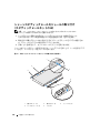
Installing the Tray and Cable-Management Arm (Sliding Rail Kits Only)
. . . 22
Installing the Tray
. . . . . . . . . . . . . . . . . . . . . . . . . . . . . . 22
Installing the Cable-Management Arm
. . . . . . . . . . . . . . . . . . . 23
Routing Cables
. . . . . . . . . . . . . . . . . . . . . . . . . . . . . . . 24
Removing the System From the Rack
. . . . . . . . . . . . . . . . . . . . . . 25
Removing a System With Sliding Rails
. . . . . . . . . . . . . . . . . . . 25
Removing a System With Static Rails
. . . . . . . . . . . . . . . . . . . . 25

4 Contents
2 Two-Post Rack Installation . . . . . . . . . . . . . . . . . . . . . . . 27
Safety Instructions . . . . . . . . . . . . . . . . . . . . . . . . . . . . . . . . 27
SAFETY: Rack Mounting of Systems
. . . . . . . . . . . . . . . . . . . . 27
Before You Begin
. . . . . . . . . . . . . . . . . . . . . . . . . . . . . . . . . 28
Important Safety Information
. . . . . . . . . . . . . . . . . . . . . . . . 28
Recommended Tools and Supplies
. . . . . . . . . . . . . . . . . . . . . 28
Rack Kit Contents
. . . . . . . . . . . . . . . . . . . . . . . . . . . . . . 29
Installation Tasks
. . . . . . . . . . . . . . . . . . . . . . . . . . . . . . 30
Marking the Rack
. . . . . . . . . . . . . . . . . . . . . . . . . . . . . . . . 30
Universal-Hole Spacing Racks
. . . . . . . . . . . . . . . . . . . . . . . 30
Wide-Hole Spacing Racks
. . . . . . . . . . . . . . . . . . . . . . . . . 31
Installing the Mounting Rails
. . . . . . . . . . . . . . . . . . . . . . . . . . 32
Center-Mount Installation
. . . . . . . . . . . . . . . . . . . . . . . . . 32
Flush-Mount Installation
. . . . . . . . . . . . . . . . . . . . . . . . . . 33
Installing Chassis Static Rail Modules
. . . . . . . . . . . . . . . . . . . . . 36
Installing the System in the Rack
. . . . . . . . . . . . . . . . . . . . . . . . 37
Removing the System From the Rack
. . . . . . . . . . . . . . . . . . . . . . 37
Index . . . . . . . . . . . . . . . . . . . . . . . . . . . . . . . . . . . . . . . . . 39

Four-Post Rack Installation 5
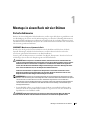
Four-Post Rack Installation
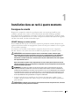
Safety Instructions
Use the following safety guidelines to ensure your own personal safety and to help protect your system
and working environment from potential damage. For complete safety and regulatory information,
see the
Product Information
Guide
that shipped with your system. Warranty information might be
included in this document or as a separate document.
SAFETY: Rack Mounting of Systems
Observe the following precautions for rack stability and safety. Also refer to the rack installation
documentation accompanying the system and the rack for specific caution statements and
procedures.
Systems are considered to be components in a rack. Thus, "component" refers to any system as well
as to various peripherals or supporting hardware.
CAUTION: Before installing systems in a rack, install front and side stabilizers on stand-alone racks or the
front stabilizer on racks joined to other racks. Failure to install stabilizers accordingly before installing
systems in a rack could cause the rack to tip over, potentially resulting in bodily injury under certain
circumstances. Therefore, always install the stabilizer(s) before installing components in the rack.
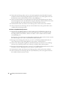
After installing system/components in a rack, never pull more than one component out of the rack on its slide
assemblies at one time. The weight of more than one extended component could cause the rack to tip over
and may result in serious injury.
NOTE: Your system is safety-certified as a free-standing unit and as a component for use in a Dell rack
cabinet using the customer rack kit. The installation of your system and rack kit in any other rack cabinet has
not been approved by any safety agencies. It is your responsibility to ensure that the final combination of
system and rack complies with all applicable safety standards and local electric code requirements. Dell
disclaims all liability and warranties in connection with such combinations.
• System rack kits are intended to be installed in a rack by trained service technicians. If you install
the kit in any other rack, be sure that the rack meets the specifications of a Dell rack.
CAUTION: Do not move racks by yourself. Due to the height and weight of the rack, a minimum of two
people should accomplish this task.
• Before working on the rack, make sure that the stabilizers are secured to the rack, extended to
the floor, and that the full weight of the rack rests on the floor. Install front and side stabilizers
on a single rack or front stabilizers for joined multiple racks before working on the rack.
• Always load the rack from the bottom up, and load the heaviest item in the rack first.

6 Four-Post Rack Installation
• Make sure that the rack is level and stable before extending a component from the rack.
• Use caution when pressing the component rail release latches and sliding a component into or out
of a rack; the slide rails can pinch your fingers.
• Do not overload the AC supply branch circuit that provides power to the rack. The total rack load
should not exceed 80 percent of the branch circuit rating.
• Ensure that proper airflow is provided to components in the rack.
• Do not step on or stand on any component when servicing other components in a rack.
General Installation Instructions
This installation guide provides instructions for trained service technicians installing one or more systems
in a rack cabinet. The RapidRails™ rack kit can be installed in all the system manufacturer's rack cabinets
without tools, and the VersaRails™ rack kit can be installed in most industry-standard rack cabinets. The
procedures for installing both RapidRails and VersaRails rack kits are similar. One rack kit is required for
each system to be installed in the rack cabinet.
This section includes procedures for the following four-post rack kits:
• Sliding rails rack kit
• Static rails rack kit (RapidRails and VersaRails versions)
(See "Two-Post Rack Installation" on page 27 for instructions on installing a static rails kit in a two-post
rack.)
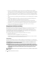
Before You Begin
Before you begin installing your system in the rack, carefully read "Safety Instructions," found earlier
in this guide, as well as the safety instructions found in your Product Information Guide for additional
information.
CAUTION: When installing multiple systems in a rack, complete all of the procedures for the current system
before attempting to install the next system.
CAUTION: Rack cabinets can be extremely heavy and move easily on their casters. They do not have brakes. Use
extreme caution while moving the rack cabinet. Retract the leveling feet when relocating the rack cabinet. Avoid
long or steep inclines or ramps where loss of cabinet control may occur. Extend the leveling feet for support and
to prevent the cabinet from rolling.
NOTE: For instructions on installing the system itself, see ""Installing the System in the Rack" on page 18.

Four-Post Rack Installation 7
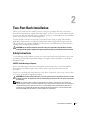
Important Safety Information
Observe the safety precautions in the following subsections when installing your system in the rack.
CAUTION: You must strictly follow the procedures in this document to protect yourself as well as others who
may be involved. Your system may be very large and heavy and proper preparation and planning are important to
prevent injury to yourself and to others. This precaution becomes increasingly important when systems are
installed high up in the rack.
CAUTION: Do not install rack kit components designed for another system. Use only the rack kit for your system.
Using the rack kit for another system may result in damage to the system and personal injury to yourself and to
others.
Rack Requirements for VersaRails
NOTICE: The VersaRails rack kit is intended to be installed by trained service technicians in a rack that meets the
specifications of American National Standards Institute (ANSI)/Electronic Industries Association (EIA) standard
ANSI/EIA-310-D-92, International Electrotechnical Commission (IEC) 297, and Deutsche Industrie Norm (DIN) 41494.
One rack kit is required for each system that is installed in a rack.
Rack Stabilizer Feet
CAUTION: Before installing systems in a rack, install front and side stabilizers on stand-alone racks or the front
stabilizer on racks joined to other racks. Failure to install stabilizers accordingly before installing systems in a
rack could cause the rack to tip over, potentially resulting in bodily injury under certain circumstances.
Therefore, always install the stabilizer(s) before installing components in the rack.
The stabilizer feet help prevent the rack from tipping over. See the documentation provided with the rack
cabinet for instructions on installing and anchoring the stabilizer feet.
Recommended Tools and Supplies
You may need the following items to install the system in a four-post rack cabinet:
• #2 Phillips screwdriver
• Masking tape or a felt-tip pen, for use in marking the mounting holes to be used

8 Four-Post Rack Installation
Sliding Rails Rack Kit Contents
• One pair of slide assemblies (convertible to RapidRails or VersaRails configuration)
• One cable-management arm
•One tray
• One status indicator cable (if applicable)
• Tie wraps to secure the cables to the cable management arm
• Eight 10-32 x 0.5-inch flange-head Phillips screws (used in VersaRails configuration only)
NOTE: The nonmetric screws described in illustrations and in procedural steps are identified by size and number
of threads per inch. For example, a #10 Phillips-head screw with 32 threads per inch is identified as a 10-32 screw.
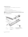
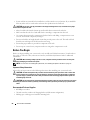
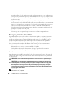
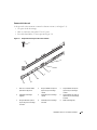
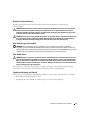
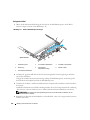
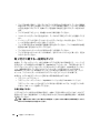
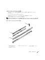
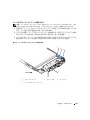
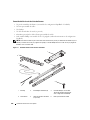
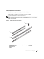
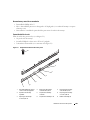
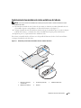
Figure 1-1. Sliding Rails Rack Kit Contents
1 tray 2 slide assemblies (2) 3 10-32 x 0.5-inch flange-head Phillips
screws (8) (VersaRails configuration only)
4 tie wraps 5 status indicator cable
(if applicable)
6 cable-management arm
1
2
3
5
6
4

Four-Post Rack Installation 9
Static Rails Rack Kit Contents
• One pair of static mounting rails with either VersaRails brackets or RapidRails brackets.
• One pair of chassis static rail modules
• 10-32 x 0.5-inch flange-head Phillips screws (8) (VersaRails kits only)
• Releasable tie wraps (2) (not shown in Figure 1-2)
NOTE: The nonmetric screws described in illustrations and in procedural steps are identified by size and number
of threads per inch. For example, a #10 Phillips-head screw with 32 threads per inch is identified as a 10-32 screw.
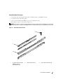
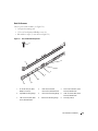
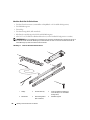
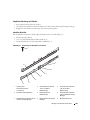
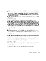
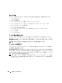
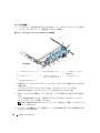
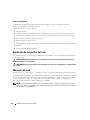
Figure 1-2. Static Rails Rack Kit Contents
1 10-32 x 0.5-inch flange-head
Phillips screws (8)
(VersaRails kits only)
2 static mounting rails (2) 3 chassis static rail modules (2)
FRONT
L
1
3
2

10 Four-Post Rack Installation
Installation Tasks
Installing a rack kit involves performing the following tasks (described in detail in subsequent sections)
in their numbered order:
1
Removing the rack doors
2
Marking the rack
3
Configuring the sliding rail assemblies (sliding rail kits only)
4
Installing chassis static rail modules (static rail kits only)
5
Installing the mounting rails in the rack
6
Installing the system in the rack
7
Installing the tray and cable-management arm (sliding rail kits only)
8
Routing cables
9
Replacing the rack doors
Removing the Rack Doors
See the procedures for removing doors in the documentation provided with your rack cabinet.
CAUTION: Because of the size and weight of the rack cabinet doors, never attempt to remove or install them
by yourself.
CAUTION: Store the two doors where they will not injure someone if the doors accidently fall over.
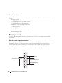
Marking the Rack
For a 1-U system, you must allow 1 U (44 mm, or 1.75 inches) of vertical space for each system you install
in the rack.
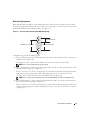
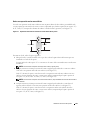
Rack cabinets that meet EIA-310 standards have an alternating pattern of three holes per rack unit with
center-to-center hole spacing (beginning at the top hole of a 1-U space) of 15.9 mm, 15.9 mm, and 12.7 mm
(0.625 inch, 0.625 inch, and 0.5 inch) for the front and back vertical rails (see Figure 1-3). Rack cabinets may
have round or square holes.
NOTE: The vertical rails may be marked by horizontal lines and numbers in 1-U increments. If you want, you can
make a note of the number marking on the rack’s vertical rail. It is not necessary to mark or place tape on the rack.

Four-Post Rack Installation 11
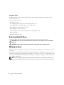
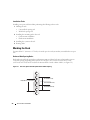
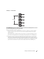
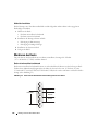
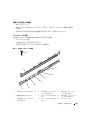
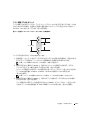
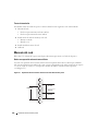
Figure 1-3. One Rack Unit
CAUTION: If you are installing more than one system, install the mounting rails so that the first system is
installed in the lowest available position in the rack.
To mark the rack, perform the following steps:
1
Place a mark (or tape) on the rack's front vertical rails where you want to locate the bottom
of the system you are installing in the rack.
The bottom of each 1-U space is at the middle of the narrowest metal area between holes (marked
with a horizontal line on some rack cabinets—see Figure 1-4).
2
Place a mark 44 mm (1.75 inches) above the original mark you made (or count up three holes in a rack
that meets EIA-310 standards) and mark the rack's front vertical rails with a felt-tipped pen or masking
tape (if you counted holes, place a mark just above the top hole). This mark or piece of tape indicates
where the system's upper edge will be located on the vertical rails (see Figure 1-4).
1 U (44 mm or 1.75 inches)
12.7 mm (0.5 inch)
15.9 mm (0.625 inch)
15.9 mm (0.625 inch)
12.7 mm (0.5 inch)

12 Four-Post Rack Installation
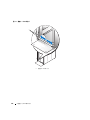
Figure 1-4. Marking the Vertical Rails
1 marks on vertical rail (2)
1

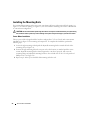
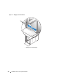
Four-Post Rack Installation 13
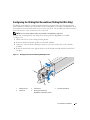
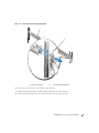
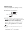
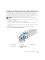
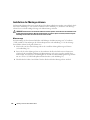
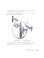
Configuring the Sliding Rail Assemblies (Sliding Rail Kits Only)
The sliding rail assembly has a rotating mounting bracket at each end of the rail. The position of the
bracket determines whether the rail assembly is used as a RapidRail or a VersaRail. The RapidRail side of
the bracket has a hook and a latch that secure it to the vertical rail. The VersaRail side of the bracket has
three holes and uses screws to attach it to the vertical rail.
NOTE: The rack kit ships with the sliding rail assemblies in the RapidRails configuration.
To rotate the mounting bracket and change the mounting rails from RapidRails to VersaRails
(see
Figure 1-5
):
1
Lift the release lever on the rotating mounting bracket.
2
Rotate the bracket and slide it up off the two shoulder standoffs.
3
Continue to rotate the bracket 180 degrees until you can set the notches back over the shoulder
standoffs.
4
Rotate the bracket back in the opposite direction on the shoulder standoffs until the bracket clicks
into place.
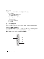
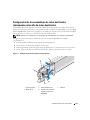
Figure 1-5. Changing the Position of the Rotating Mounting Bracket
1 rotating bracket 2 release lever 3 shoulder standoffs (2)
4 notches (2) 5 mounting bracket flange
(RapidRails configuration shown)
1
2
4
3
5

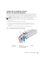
14 Four-Post Rack Installation
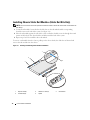
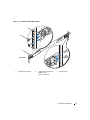
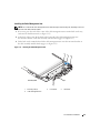
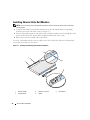
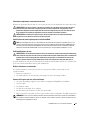
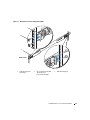
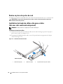
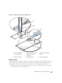
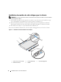
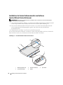
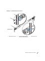
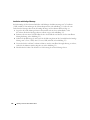
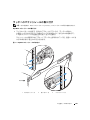
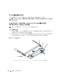
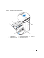
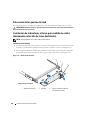
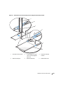
Installing Chassis Static Rail Modules (Static Rail Kits Only)
NOTE: You do not need to remove the optional front bezel to install or remove the chassis static rail modules from
the chassis.
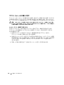
1
To install a rail module, locate the three keyhole slots on the rail module and the corresponding
shoulder screws on the side of the system (see Figure 1-6).
2
Place the rail module against the side of the system so that the shoulder screws fit through the round
portion of the keyhole slots, then slide the module towards the back of the system.
3
Repeat steps 1 and 2 to install the other rail module.
To remove a
rail module
from the chassis, pull up on the release latch, then slide the rail forward and
remove the rail module from the chassis.
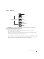
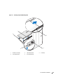
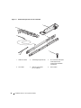
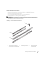
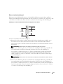
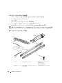
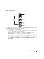
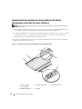
Figure 1-6. Installing and Removing Static Rail Chassis Modules
1 keyhole slots (6) 2 shoulder screws (6) 3 release latch
4 rail modules (2) 5 system
4
2
3
1
5

Four-Post Rack Installation 15
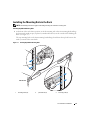
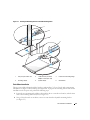
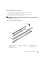
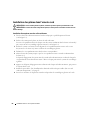
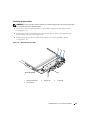
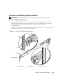
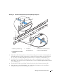
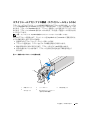
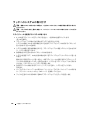
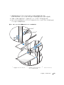
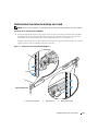
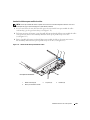
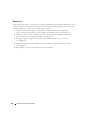
Installing the Mounting Rails in the Rack
NOTE: The following instructions apply to both sliding mounting rails and static mounting rails.
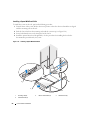
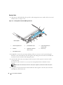
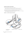
Installing RapidRails Mounting Rails
1
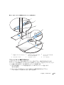
At the front of the rack cabinet, position one of the mounting rails so that its mounting-bracket flange
fits between the marks or tape you placed (or numbered locations) on the vertical rails in "Marking the
Rack" (see Figure 1-7).
The top mounting hook on the front mounting-bracket flange should enter the top hole between the
marks you made on the vertical rails.
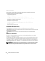
Figure 1-7. Installing RapidRails Mounting Rails
1 mounting hooks (2) 2 push buttons (2) 3 mounting rails (2)
front of rack
1
2
3

16 Four-Post Rack Installation
2
Push the mounting rail forward until the mounting hook enters the square hole, and then push down
on the mounting-bracket flange until the mounting hook seats and the push button extends through
the lower square hole (see Figure 1-7).
3
At the back of the cabinet, pull back on the mounting-bracket flange until the mounting hook enters
the upper square hole, and then push down on the flange until the mounting hook seats and the push
button extends through the lower square hole.
4
Repeat step 1 through step 3 for the mounting rail on the other side of the rack.
5
Confirm that the mounting rails are mounted at the same vertical position on both sides of the rack.
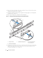
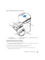
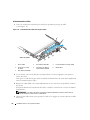
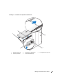
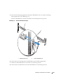
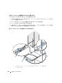
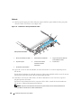
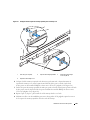
Installing the VersaRails Mounting Rails
1
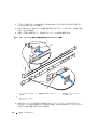
At the front of the rack cabinet, position one of the mounting rails so that its mounting-bracket flange
fits between the marks you placed (or numbered locations) on the vertical rails in "Marking the Rack"
(see Figure 1-8).
The three holes on the front of the mounting-bracket flange should align with the holes between the
marks you made on the front vertical rail.
2
Install two 10-32 x 0.5-inch flange-head Phillips screws in the upper and lower holes in the mounting-
bracket flange to secure the mounting rail to the front vertical rail.
3
At the back of the cabinet, pull back on the mounting-bracket flange until the mounting holes align
with their respective holes on the back vertical rail.
4
Install two 10-32 x 0.5-inch flange-head Phillips screws in the upper and lower holes in the mounting-
bracket flange to secure the mounting rail to the back vertical rail.
5
Repeat step 1 through step 4 for the mounting rail on the other side of the rack.
6
Ensure that the mounting rails are mounted at the same position on the vertical rails on each side
of the rack.

Four-Post Rack Installation 17
Figure 1-8. Installing VersaRails Mounting Rails
1 mounting-bracket flange 2 10-32 x 0.5-inch flange-head
Phillips screws
(4 per mounting rail)
3 mounting rails (2)
front of rack
1
2
3

18 Four-Post Rack Installation
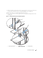
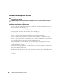
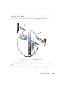
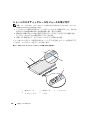
Installing the System in the Rack
CAUTION: If you are installing more than one system, install the first system in the lowest available position
in the rack.
CAUTION: Because of the size and weight of the system, never attempt to install the system in the mounting rails
by yourself.
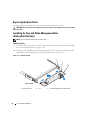
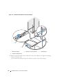
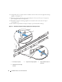
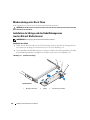
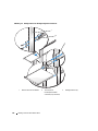
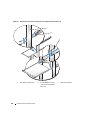
Installing a System With Sliding Rails
1
Pull the two inner slide rails out of the rack until they lock in the fully extended position
(see Figure 1-9).
2
Lift the system into position above the extended slides.
The three shoulder screws on each side of the system fit into the corresponding J-slots on the inner
slide assemblies (see Figure 1-9).
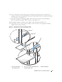
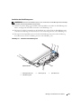
3
Lower the back of the system while aligning the back shoulder screws on the sides of the system with
the back J-slots on the slide assemblies.
4
Engage the back shoulder screws into their respective J-slots.
5
Lower the front of the system and fit the middle and front shoulder screws into the J-slots in the slide
assemblies.
The system release latch at the front of the inner slide rail will snap back as the shoulder screw passes
into the front slot. Use this system release latch when you wish to remove the system from the slide
assemblies.
6
Press the slide-release latch on the outside of each inner slide, then push the system into the rack.
7
Install the cable-management arm. See "Installing the Tray and Cable-Management Arm
(Sliding Rail Kits Only)" on page 22.
8
Tighten the thumbscrews on the rack front panel to secure the slide assemblies to the rack.
Seite wird geladen ...
Seite wird geladen ...
Seite wird geladen ...
Seite wird geladen ...
Seite wird geladen ...
Seite wird geladen ...
Seite wird geladen ...
Seite wird geladen ...
Seite wird geladen ...
Seite wird geladen ...
Seite wird geladen ...
Seite wird geladen ...
Seite wird geladen ...
Seite wird geladen ...
Seite wird geladen ...
Seite wird geladen ...
Seite wird geladen ...
Seite wird geladen ...
Seite wird geladen ...
Seite wird geladen ...
Seite wird geladen ...
Seite wird geladen ...
Seite wird geladen ...
Seite wird geladen ...
Seite wird geladen ...
Seite wird geladen ...
Seite wird geladen ...
Seite wird geladen ...
Seite wird geladen ...
Seite wird geladen ...
Seite wird geladen ...
Seite wird geladen ...
Seite wird geladen ...
Seite wird geladen ...
Seite wird geladen ...
Seite wird geladen ...
Seite wird geladen ...
Seite wird geladen ...
Seite wird geladen ...
Seite wird geladen ...
Seite wird geladen ...
Seite wird geladen ...
Seite wird geladen ...
Seite wird geladen ...
Seite wird geladen ...
Seite wird geladen ...
Seite wird geladen ...
Seite wird geladen ...
Seite wird geladen ...
Seite wird geladen ...
Seite wird geladen ...
Seite wird geladen ...
Seite wird geladen ...
Seite wird geladen ...
Seite wird geladen ...
Seite wird geladen ...
Seite wird geladen ...
Seite wird geladen ...
Seite wird geladen ...
Seite wird geladen ...
Seite wird geladen ...
Seite wird geladen ...
Seite wird geladen ...
Seite wird geladen ...
Seite wird geladen ...
Seite wird geladen ...
Seite wird geladen ...
Seite wird geladen ...
Seite wird geladen ...
Seite wird geladen ...
Seite wird geladen ...
Seite wird geladen ...
Seite wird geladen ...
Seite wird geladen ...
Seite wird geladen ...
Seite wird geladen ...
Seite wird geladen ...
Seite wird geladen ...
Seite wird geladen ...
Seite wird geladen ...
Seite wird geladen ...
Seite wird geladen ...
Seite wird geladen ...
Seite wird geladen ...
Seite wird geladen ...
Seite wird geladen ...
Seite wird geladen ...
Seite wird geladen ...
Seite wird geladen ...
Seite wird geladen ...
Seite wird geladen ...
Seite wird geladen ...
Seite wird geladen ...
Seite wird geladen ...
Seite wird geladen ...
Seite wird geladen ...
Seite wird geladen ...
Seite wird geladen ...
Seite wird geladen ...
Seite wird geladen ...
Seite wird geladen ...
Seite wird geladen ...
Seite wird geladen ...
Seite wird geladen ...
Seite wird geladen ...
Seite wird geladen ...
Seite wird geladen ...
Seite wird geladen ...
Seite wird geladen ...
Seite wird geladen ...
Seite wird geladen ...
Seite wird geladen ...
Seite wird geladen ...
Seite wird geladen ...
Seite wird geladen ...
Seite wird geladen ...
Seite wird geladen ...
Seite wird geladen ...
Seite wird geladen ...
Seite wird geladen ...
Seite wird geladen ...
Seite wird geladen ...
Seite wird geladen ...
Seite wird geladen ...
Seite wird geladen ...
Seite wird geladen ...
Seite wird geladen ...
Seite wird geladen ...
Seite wird geladen ...
Seite wird geladen ...
Seite wird geladen ...
Seite wird geladen ...
Seite wird geladen ...
Seite wird geladen ...
Seite wird geladen ...
Seite wird geladen ...
Seite wird geladen ...
Seite wird geladen ...
Seite wird geladen ...
Seite wird geladen ...
Seite wird geladen ...
Seite wird geladen ...
Seite wird geladen ...
Seite wird geladen ...
Seite wird geladen ...
Seite wird geladen ...
Seite wird geladen ...
Seite wird geladen ...
Seite wird geladen ...
Seite wird geladen ...
Seite wird geladen ...
Seite wird geladen ...
Seite wird geladen ...
Seite wird geladen ...
Seite wird geladen ...
Seite wird geladen ...
Seite wird geladen ...
Seite wird geladen ...
Seite wird geladen ...
Seite wird geladen ...
Seite wird geladen ...
Seite wird geladen ...
Seite wird geladen ...
Seite wird geladen ...
Seite wird geladen ...
Seite wird geladen ...
Seite wird geladen ...
Seite wird geladen ...
Seite wird geladen ...
Seite wird geladen ...
Seite wird geladen ...
Seite wird geladen ...
Seite wird geladen ...
Seite wird geladen ...
Seite wird geladen ...
Seite wird geladen ...
Seite wird geladen ...
Seite wird geladen ...
Seite wird geladen ...
Seite wird geladen ...
Seite wird geladen ...
Seite wird geladen ...
-
 1
1
-
 2
2
-
 3
3
-
 4
4
-
 5
5
-
 6
6
-
 7
7
-
 8
8
-
 9
9
-
 10
10
-
 11
11
-
 12
12
-
 13
13
-
 14
14
-
 15
15
-
 16
16
-
 17
17
-
 18
18
-
 19
19
-
 20
20
-
 21
21
-
 22
22
-
 23
23
-
 24
24
-
 25
25
-
 26
26
-
 27
27
-
 28
28
-
 29
29
-
 30
30
-
 31
31
-
 32
32
-
 33
33
-
 34
34
-
 35
35
-
 36
36
-
 37
37
-
 38
38
-
 39
39
-
 40
40
-
 41
41
-
 42
42
-
 43
43
-
 44
44
-
 45
45
-
 46
46
-
 47
47
-
 48
48
-
 49
49
-
 50
50
-
 51
51
-
 52
52
-
 53
53
-
 54
54
-
 55
55
-
 56
56
-
 57
57
-
 58
58
-
 59
59
-
 60
60
-
 61
61
-
 62
62
-
 63
63
-
 64
64
-
 65
65
-
 66
66
-
 67
67
-
 68
68
-
 69
69
-
 70
70
-
 71
71
-
 72
72
-
 73
73
-
 74
74
-
 75
75
-
 76
76
-
 77
77
-
 78
78
-
 79
79
-
 80
80
-
 81
81
-
 82
82
-
 83
83
-
 84
84
-
 85
85
-
 86
86
-
 87
87
-
 88
88
-
 89
89
-
 90
90
-
 91
91
-
 92
92
-
 93
93
-
 94
94
-
 95
95
-
 96
96
-
 97
97
-
 98
98
-
 99
99
-
 100
100
-
 101
101
-
 102
102
-
 103
103
-
 104
104
-
 105
105
-
 106
106
-
 107
107
-
 108
108
-
 109
109
-
 110
110
-
 111
111
-
 112
112
-
 113
113
-
 114
114
-
 115
115
-
 116
116
-
 117
117
-
 118
118
-
 119
119
-
 120
120
-
 121
121
-
 122
122
-
 123
123
-
 124
124
-
 125
125
-
 126
126
-
 127
127
-
 128
128
-
 129
129
-
 130
130
-
 131
131
-
 132
132
-
 133
133
-
 134
134
-
 135
135
-
 136
136
-
 137
137
-
 138
138
-
 139
139
-
 140
140
-
 141
141
-
 142
142
-
 143
143
-
 144
144
-
 145
145
-
 146
146
-
 147
147
-
 148
148
-
 149
149
-
 150
150
-
 151
151
-
 152
152
-
 153
153
-
 154
154
-
 155
155
-
 156
156
-
 157
157
-
 158
158
-
 159
159
-
 160
160
-
 161
161
-
 162
162
-
 163
163
-
 164
164
-
 165
165
-
 166
166
-
 167
167
-
 168
168
-
 169
169
-
 170
170
-
 171
171
-
 172
172
-
 173
173
-
 174
174
-
 175
175
-
 176
176
-
 177
177
-
 178
178
-
 179
179
-
 180
180
-
 181
181
-
 182
182
-
 183
183
-
 184
184
-
 185
185
-
 186
186
-
 187
187
-
 188
188
-
 189
189
-
 190
190
-
 191
191
-
 192
192
-
 193
193
-
 194
194
-
 195
195
-
 196
196
-
 197
197
-
 198
198
-
 199
199
-
 200
200
-
 201
201
-
 202
202


Dell PowerEdge 300 Schnellstartanleitung
- Kategorie
- Rack-Zubehör
- Typ
- Schnellstartanleitung