Miele PDR 914-514 EL SOM Installationsanleitung
- Kategorie
- Auto-Video-Systeme
- Typ
- Installationsanleitung

PDR914/514 EL SOM
de Installationsplan Gewerbliche Trockner
en Installation plan Commercial tumble dryers
it Pianta d'installazione Essiccatoio industriale
M.-Nr. 12 103 590

2
de ...................................................................................................................................... 4
en ...................................................................................................................................... 14
it ........................................................................................................................................ 23

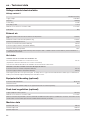
de - Inhalt
3
Installationshinweise....................................................................................................... 4
Installationsvoraussetzungen ............................................................................................ 4
Elektroanschluss ............................................................................................................... 4
Zuluft/Abluft....................................................................................................................... 5
PDR914/514, elektrobeheizt .......................................................................................... 6
Abmessungen ................................................................................................................... 6
Installation ......................................................................................................................... 7
Aufstellung (Standard/UG)................................................................................................. 8
Aufstellung (Betonsockel/Offshore)................................................................................... 9
Technische Daten ............................................................................................................ 10
Spannungsvarianten/elektrische Daten............................................................................. 10
1. Spannungsvariante.................................................................................................... 10
2.Spannungsvariante.................................................................................................... 10
3. Spannungsvariante.................................................................................................... 10
Abluft ................................................................................................................................. 10
Zuluft ................................................................................................................................. 11
Potentialausgleich (optional).............................................................................................. 11
Spitzenlastabschaltung (optional) ..................................................................................... 11
Gerätedaten....................................................................................................................... 11
Befestigungsvarianten....................................................................................................... 12
Befestigung ohne Sockel .............................................................................................. 12

de - Installationshinweise
4
Installationsvoraussetzungen
Der Trockner darf nur vom MieleKundendienst oder einem autorisierten Fachhändler
aufgestellt und in Betrieb genommen werden.
Der Trockner muss in Übereinstimmung mit geltenden Regeln und gültigen Normen in-
stalliert werden.
Betreiben Sie den Trockner immer nur in ausreichend belüfteten und nicht frostgefährde-
ten Räumen.
Der Betrieb des Gerätes ist nur dann zulässig, wenn
- die Rumpflänge des Schiffes mehr als 24Meter beträgt.
- die Neigung des Schiffes nicht mehr als 2° beträgt.
- eine von außen einwirkende Vibration nicht mehr als 150Hz bei einer Amplitude von
0,35mm beträgt.
Bei Nichtbeachten ist ein gefahrloser Betrieb und eine einwandfreie Funktion des Gerä-
tes nicht gegeben.
Der Betrieb des Gerätes auf offenem Deck ist verboten.
Geräte, die nicht mit dem „CSAC/US“-Sicherheitszeichen gekennzeichnet sind, ent-
sprechen den europäischen Sicherheitsregeln.
Diese Geräte dürfen nicht in den USA betrieben werden.
Der Einbau und die Montage dieses Gerätes darf nur von Fachbetrieben/ Fachkräften
durchgeführt werden, wenn sie die Voraussetzungen für den sicherheitsgerechten Ge-
brauch dieses Gerätes sicherstellen.
Bei Installation des Gerätes ist zu beachten, dass dieses fest fixiert wird.
Bei Nichtbeachten besteht die Gefahr einer Verletzung von Personen und einer Beschädi-
gung des Gerätes sowie anderer Gegenstände oder Einrichtungen.
Der Einsatz von Geräten der Wäschereitechnik auf Fahrzeugen, die auf Binnengewäs-
sern und innerhalb der 3 Meilen Zone verkehren, ist nur zulässig, wenn es sich um ein für
das betreffende Land oder die betreffenden Länder approbiertes Gerät handelt. Der Ein-
satz auf Fahrzeugen in internationalen Gewässern einschließlich der Seehäfen bleibt davon
unberührt.
Elektroanschluss
Der Elektroanschluss muss von einer Elektrofachkraft ausgeführt werden.
Der Elektroanschluss darf nur an eine nach den nationalen Gesetzen, Verordnungen und
Richtlinien sowie den lokalen Bestimmungen und Vorschriften ausgeführte Elektroanlage
erfolgen. Darüber hinaus sind die Vorschriften der Energieversorgungsunternehmen und
Versicherer, die Unfallverhütungsvorschriften sowie die anerkannten Regeln der Technik zu
beachten.
Der zuverlässige und sichere Betrieb des Trockners ist nur dann gewährleistet, wenn
das Gerät am öffentlichen Stromnetz angeschlossen ist.

de - Installationshinweise
5
Die erforderliche elektrische Anschlussspannung, die Leistungsaufnahme und die Vorga-
ben zur Absicherung sind auf dem Typenschild des Trockners angegeben. Vergewissern
Sie sich, dass die Anschlussspannung mit den Spannungswerten auf dem Typenschild
übereinstimmt, bevor der Elektroanschluss ausgeführt wird!
Bei abweichenden Spannungswerten besteht die Gefahr, dass der Trockner durch eine
zu hohe elektrische Anschlussspannung beschädigt wird.
Wenn auf dem Typenschild mehrere Spannungswerte angegeben sind, kann der Trock-
ner für den Anschluss an die jeweilige Eingangsspannung umgeschaltet werden. Diese
Umschaltung darf nur vom MieleKundendienst oder autorisierten Fachhandel durchgeführt
werden. Bei der Umschaltung ist die Umverdrahtungsanweisung auf dem Schaltplan zu
beachten.
Der Trockner kann entweder über einen Festanschluss oder über eine Steckvorrichtung
nach IEC60309-1 angeschlossen werden. Für einen Festanschluss muss am Aufstellungs-
ort eine allpolige Netztrenneinrichtung vorhanden sein.
Als Netztrenneinrichtung gelten Schalter mit einer Kontaktöffnung von mehr als 3mm.
Dazu gehören z.B. Leitungsschutzschalter, Sicherungen und Schütze (IEC/EN60947).
Die Netztrenneinrichtung (einschließlich der Steckvorrichtung) muss gegen unbeabsichtig-
tes und unbefugtes Einschalten gesichert sein, wenn eine permanente Unterbrechung der
Energiezufuhr nicht von jeder Zugangsstelle aus zu überwachen ist.
Tipp: Der Trockner sollte bevorzugt über Steckvorrichtungen angeschlossen werden, damit
elektrische Sicherheitsprüfungen einfacher durchgeführt werden können (z.B. während ei-
ner Wartung oder Instandsetzung).
Es dürfen keine Einrichtungen installiert werden, die den Trockner automatisch aus-
schalten (z.B. Zeitschaltuhren).
Ist es nach lokalen Vorgaben erforderlich einen Fehlerstromschutzschalter (RCD) zu in-
stallieren, muss zwingend ein Fehlerstromschutzschalter TypB (allstromsensitiv) verwen-
det werden.
Wenn örtliche und nationale Installationsbestimmungen einen Potentialausgleich erfor-
dern, muss ein Potentialausgleich mit guter Kontaktverbindung hergestellt werden. Der Po-
tentialausgleich muss bei einem Ableitstrom von >10mA durchgeführt werden.
Zuluft/Abluft
Der Trockner darf nur betrieben werden, wenn eine Abluftleitung ordnungsgemäß ange-
schlossen ist und für eine ausreichende Raumbelüftung gesorgt ist.
Zubehörteile dürfen nur dann an- oder eingebaut werden, wenn sie ausdrücklich von
Miele freigegeben sind. Wenn andere Teile an- oder eingebaut werden, gehen Ansprüche
aus Garantie, Gewährleistung und/oder Produkthaftung verloren.

de - PDR914/514, elektrobeheizt
6
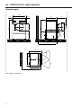
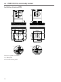
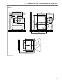
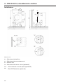
Abmessungen
906
900 >20>20
Ø 520
650
1400
595 Ø 630
20
1400
752 642
38
67
852
747
1300
1300
747
852
900
906
< 180°
45°
Maßangaben in Millimetern

de - PDR914/514, elektrobeheizt
7
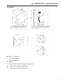
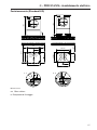
Installation
620 280
183
SLA
1342
305
1600
150
305
1600
~ 50
2 x
150
128
200
EL
AL ZL
PA
ZL
PA
EL
AL
128
SLA
PA
SLA
ZL
EL
AL
AL
ZL
161
160
"Z"
"Y"
"Y"
"Z"
XCI
96
31
Maßangaben in Millimetern
EL Elektroanschluss
AL Abluftanschluss
ZL Zuluft
PA Anschluss für Potentialausgleich (optional)
SLA Spitzenlastanschluss (optional)
XCI XCI-/Connector-Box (optional)

de - PDR914/514, elektrobeheizt
8
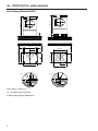
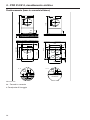
Aufstellung (Standard/UG)
20
1400
Ø 12
1400
UG
UG 900
B
~ 48
55
747
~ 55
127
Ø 10
~ 65
B
1300
55
790
395
754
900
546
BB
A
A
UG 685
409
818
587
617
B
B
B
BB
B
A - A B - B
Maßangaben in Millimetern
UG Unterbau geschlossen
BBefestigungspunkt/Bohrloch

de - PDR914/514, elektrobeheizt
9
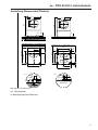
Aufstellung (Betonsockel/Offshore)
20
1400
M6 x 20
1400
BS
900
B
~ 48
>55
BS >900
>50
20
Ø 10
B
BS 1300
>55
790
395
754
BS >900
546
BB
C
C
747
463
926
546
651
D
D
B
BB
B
>50
BS
1300
790
55 55
103
395
BS
~55
OFFSHORE
C - C D - D ~ 48
Maßangaben in Millimetern
BS Betonsockel
BBefestigungspunkt/Bohrloch

de - Technische Daten
10
Spannungsvarianten/elektrische Daten
1. Spannungsvariante
Standardanschluss Umschaltbar für
Anschlussspannung 3 AC 480V 3 AC 440V
Frequenz 50/60Hz 50/60Hz
Leistungsaufnahme 16,5kW 14,1kW
Elektrische Absicherung (bauseitig) 3×25A 3×25A
Mindestquerschnitt für Anschlusskabel 4×2,5mm² 4×2,5mm²
Kabelverschraubung M25 M25
2.Spannungsvariante
Standardanschluss
Anschlussspannung 3 AC 400V
Frequenz 50/60Hz
Leistungsaufnahme 14,1kW
Elektrische Absicherung (bauseitig) 3×25A
Mindestquerschnitt für Anschlusskabel 4×2,5mm²
Kabelverschraubung M25
3. Spannungsvariante
Standardanschluss Umschaltbar für
Anschlussspannung 3 AC 220–240V 3 AC 200–208V
Frequenz 50/60Hz 50/60Hz
Leistungsaufnahme 12,9–15,3kW 10,8–11,7kW
Elektrische Absicherung (bauseitig) 3×35A 3×35A
Mindestquerschnitt für Anschlusskabel 4×6mm² 4×6mm²
Kabelverschraubung M32 M32
Abluft
Maximaler Nennvolumenstrom im Abluftbetrieb (nur PDR9xx) 580m³/h
Maximaler Nennvolumenstrom (nur PDR5xx) 520m³/h
Maximal zulässiger Druckverlust 220Pa
Anschlussstutzen, maschinenseitig (Außendurchmesser) 150mm
Anschlussrohr, bauseitig (Innendurchmesser) 150mm
Maximale Ablufttemperatur 80°C
Da die relative Luftfeuchtigkeit innerhalb der Abluftführung bis zu 100% betragen kann, muss durch geeignete Maßnahmen ausge-
schlossen werden, dass zurückfließendes Kondensat in das Gerät gelangen kann.

de - Technische Daten
11
Zuluft
Standardanschluss: Zuluft aus dem Aufstellraum
Empfohlener freier Zuluftquerschnitt in den Raum:
(Entspricht dem 3-fachen Abluftquerschnitt eines Gerätes).
531cm²
Dem Aufstellraum muss entsprechend der Abluftmenge Zuluft zugeführt werden.
Alternativanschluss: Zuluftanschluss direkt von außen
Anschlussmuffe, maschinenseitig (Innendurchmesser) 161mm
Anschlussrohr, bauseitig (Außendurchmesser) 160mm
Beim Entfernen des Schutzdeckels werden spannungsführende Teile frei. Aus Sicherheitsgründen muss an der zentralen Frischluftan-
saugung des Trockners (über eine Mindestlänge von 900 mm) ein Rohr installiert und mit 2Schrauben gesichert werden.
Potentialausgleich (optional)
Außengewindestutzen 10×35mm
Unterlegscheiben und Mutter M10
Das für einen Potentialausgleich erforderliche Zubehör ist nicht im Lieferumfang enthalten.
Spitzenlastabschaltung (optional)
Anschlussspannung der Steuerungskontakte AC 230V
Mindestquerschnitt für Anschlusskabel 5×1,5mm²
Miele empfiehlt, den Anschluss mit einer flexiblen Anschlussleitung und einer zusätzlichen Trennmöglichkeit herzustellen. Die Trennein-
richtung sollte nach der Geräteaufstellung sichtbar und frei zugänglich sein.
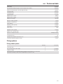
Gerätedaten
Gerätebreite über alles 906mm
Gerätehöhe über alles 1.400mm
Gerätetiefe über alles 852mm
Nischenbreite 1.250mm
Empfohlener Wandabstand (bis Gerätevorderkante) 1.300mm
Mindestwandabstand (bis zur Deckelhinterkante) 500mm
Verpackungsbreite 1.090mm
Verpackungshöhe 1.526mm
Verpackungstiefe 938mm
Maximales Bruttovolumen 1.560,2l
Maximales Bruttogewicht 171,7kg
Maximales Nettogewicht 160,4kg
Maximale Bodenbelastung im Betrieb 1.779N
Durchmesser Abluftstutzen 150mm
Trommeldurchmesser 850mm
Trommelöffnungsdurchmesser 520mm
Trommeltiefe 480mm
Trommelvolumen 250l
Türöffnungsdurchmesser 520mm
Maximaler Türöffnungswinkel 180°
Emissions-Schalldruckpegel 51 dB(A) re 20 µPa
Schallleistungspegel 62
Durchschnittliche Wärmeabgabe an den Raum 3,9MJ/h

de - Technische Daten
12
Zulässiger Umgebungstemperaturbereich 2–40°C
Befestigungsvarianten
Befestigung ohne Sockel
Anzahl Schraubengröße
Spannlaschen 2
Holzschrauben DIN 571 (Ø×Länge) 2 6×40mm
Dübel (Ø×Länge) 2 10×50mm
Bei einer Geräteaufstellung ohne Sockel wird eine Gerätebefestigung empfohlen.
Das Befestigungsmaterial für schwimmenden Estrich muss bauseitig gestellt werden.

en - Contents
13
Installation notes ............................................................................................................. 14
Installation requirements ................................................................................................... 14
Electrical connection......................................................................................................... 14
Air intake/exhaust air......................................................................................................... 15
PDR914/514, electrically heated ................................................................................... 16
Dimensions........................................................................................................................ 16
Installation ......................................................................................................................... 17
Installation (standard/UG).................................................................................................. 18
Installation (on concrete plinth/offshore) ........................................................................... 19
Technical data.................................................................................................................. 20
Voltage variants/electrical data ......................................................................................... 20
Voltage variant 2............................................................................................................ 20
Exhaust air......................................................................................................................... 20
Air intake............................................................................................................................ 20
Equipotential bonding (optional)........................................................................................ 20
Peak-load negotiation (optional)........................................................................................ 20
Machine data..................................................................................................................... 20
Fixing options.................................................................................................................... 21
Fixing without plinth ...................................................................................................... 21

en - Installation notes
14
Installation requirements
The tumble dryer must only be installed and commissioned by Miele Customer Service
Department or an authorised dealer.
The tumble dryer must be installed in accordance with all relevant regulations and
standards.
The dryer must only be operated in a room that has sufficient ventilation and which is
frost-free.
The machine may only be operated when the following conditions are met:
- the ship’s hull is longer than 24metres.
- the list of the vessel is not more than2°.
- any external vibration is no more than 150Hz at an amplitude of 0.35mm.
The safe operation and correct functioning of the appliance can only be guaranteed if
the above conditions are met.
The machine may not be operated on an open deck.
Machines that do not carry the “CSAC/US” safety mark, comply with European safety
regulations.
These machines must not be operated in USA.
This machine must only be installed by a qualified person who has made sure that the
conditions for its safe use are present.
When installing this machine it must be securely fixed to the floor. Failure to do this
could result in personal injury, damage to the machine and damage to other objects and
installations.
Electrical connection
The electrical connection must be established by a qualified electrician.
The electrical connection may only be made to an electrical system provided in accord-
ance with all appropriate local and national legislation, regulations and guidelines. Please
also observe the regulations set out by your insurance provider and energy supplier, acci-
dent prevention regulations, as well as recognised codes of practice.
We recommend connecting the tumble dryer to the power supply via a plug and socket
so that it is easier to conduct electrical safety checks (e.g. during maintenance or repair
work).
Reliable and safe operation of this tumble dryer is only ensured if it has been connected
to the mains electricity supply.
The required supply voltage, power rating and fuse rating can be found on the data plate
on the tumble dryer. Ensure that the supply voltage matches the voltage quoted on the
data plate before establishing the electrical connection to the tumble dryer.
Connection to a supply voltage other than the one quoted on the data plate can damage
the tumble dryer if the voltage is too high.

en - Installation notes
15
If more than one voltage is specified on the data plate, the tumble dryer can be conver-
ted for connection to the relevant input voltage. This conversion must be performed by the
Miele Customer Service Department or by an authorised dealer. During the conversion, the
wiring instructions given on the wiring diagram must be followed.
The tumble dryer can either be hard-wired or connected using a plug-and-socket connec-
tion in accordance with IEC60309-1. For a hard-wired connection, an all-pole isolation
device must be available at the installation site.
An isolation device is a switch which ensures a contact opening of more than 3mm.
These include circuit breakers, fuses and contactors (IEC/EN60947).
If the mains supply cannot be permanently disconnected, the isolation device (including
plug and socket) must be safeguarded against being switched on either unintentionally or
without authorisation.
The tumble dryer must not be connected to devices such as timers which would switch
it off automatically.
If local regulations require that a residual current device (RCD) is installed, a typeB re-
sidual current device (sensitive to universal current) must be used.
If local and national installation specifications require equipotential bonding, good gal-
vanic contact must be guaranteed. Equipotential bonding must have an earth current rat-
ing >10mA.
Air intake/exhaust air
The tumble dryer may only be operated when the ducting has been connected properly
and the room is sufficiently ventilated.
Accessory parts may only be fitted when expressly approved by Miele. If other parts are
used, warranty, performance and product liability claims will be invalidated.

en - PDR914/514, electrically heated
16
Dimensions
906
900 >20>20
Ø 520
650
1400
595 Ø 630
20
1400
752 642
38
67
852
747
1300
1300
747
852
900
906
< 180°
Dimensions quoted in millimetres

en - PDR914/514, electrically heated
17
Installation
620 280
183
SLA
1342
305
1600
150
305
1600
~ 50
2 x
150
128
200
EL
AL ZL
PA
ZL
PA
EL
AL
128
SLA
PA
SLA
ZL
EL
AL
AL
ZL
161
160
"Z"
"Y"
"Y"
"Z"
XCI
96
31
Dimensions quoted in millimetres
EL Electrical connection
AL Exhaust duct
ZL Air intake
PA Connection for equipotential bonding (optional)
SLA Peak-load connection (optional)
XCI XCI Box/Connector Box (optional)

en - PDR914/514, electrically heated
18
Installation (standard/UG)
20
1400
Ø 12
1400
UG
UG 900
B
~ 48
55
747
~ 55
127
Ø 10
~ 65
B
1300
55
790
395
754
900
546
BB
A
A
UG 685
409
818
587
617
B
B
B
BB
B
A - A B - B
Dimensions quoted in millimetres
UG Box plinth
BDrill hole/anchor point

en - PDR914/514, electrically heated
19
Installation (on concrete plinth/offshore)
20
1400
M6 x 20
1400
BS
900
B
~ 48
>55
BS >900
>50
20
Ø 10
B
BS 1300
>55
790
395
754
BS >900
546
BB
C
C
747
463
926
546
651
D
D
B
BB
B
>50
BS
1300
790
55 55
103
395
BS
~55
OFFSHORE
C - C D - D
Dimensions quoted in millimetres
BS Concrete plinth
BDrill hole/anchor point

en - Technical data
20
Voltage variants/electrical data
Voltage variant 2
Standard connection
Supply voltage 3 AC 400V
Frequency 50/60Hz
Power rating 14.1kW
Fuse rating (on site) 3×25A
Minimum cross-section for connection cable 4×2.5mm²
Cable gland M25
Exhaust air
Maximum nominal volume flow rate in extraction mode (PDR9xx
only)
580m³/h
Maximum nominal volume flow rate (PDR5xx only) 520m³/h
Maximum permitted pressure loss 220Pa
Connector on machine side (external diameter) 150mm
Connection pipe provided on site (internal diameter) 150mm
Maximum exhaust air temperature 80°C
As relative humidity inside the exhaust ducting can be as high as 100%, suitable measures must be taken to prevent a backflow of
condensate into the machine.
Air intake
Standard connection: air intake from installation site
Recommended free air intake cross-section into the room:
(equivalent to 3 times the exhaust air cross-section of a machine).
531cm²
There must be sufficient air intake to the installation site to match the air outlet volume.
Alternative connection: air intake connection directly from outdoors
Connection sleeve on machine side (internal diameter) 161mm
Connection pipe provided on site (external diameter) 160mm
Removing the protective cover exposes live parts. For safety reasons, a pipe must be installed from the tumble dryer’s central fresh air
intake (over a minimum length of 900mm) and secured with 2screws.
Equipotential bonding (optional)
Connection with male thread 10×35mm
Washers and nuts M10
Accessories for equipotential bonding are not supplied and need to be ordered separately.
Peak-load negotiation (optional)
Supply voltage for control contacts AC 230V
Minimum cross-section for connection cable 5×1.5mm²
Miele recommends using a flexible connection cable with an additional isolation option to establish the connection. The isolator should
remain visible once the tumble dryer has been installed and must be freely accessible.
Machine data
Machine width, total 906mm
Machine height, total 1400mm
Machine depth, total 852mm
Seite wird geladen ...
Seite wird geladen ...
Seite wird geladen ...
Seite wird geladen ...
Seite wird geladen ...
Seite wird geladen ...
Seite wird geladen ...
Seite wird geladen ...
Seite wird geladen ...
Seite wird geladen ...
Seite wird geladen ...
Seite wird geladen ...
-
 1
1
-
 2
2
-
 3
3
-
 4
4
-
 5
5
-
 6
6
-
 7
7
-
 8
8
-
 9
9
-
 10
10
-
 11
11
-
 12
12
-
 13
13
-
 14
14
-
 15
15
-
 16
16
-
 17
17
-
 18
18
-
 19
19
-
 20
20
-
 21
21
-
 22
22
-
 23
23
-
 24
24
-
 25
25
-
 26
26
-
 27
27
-
 28
28
-
 29
29
-
 30
30
-
 31
31
-
 32
32


Miele PDR 914-514 EL SOM Installationsanleitung
- Kategorie
- Auto-Video-Systeme
- Typ
- Installationsanleitung
in anderen Sprachen
Verwandte Artikel
-
Miele PDR 922/522 EL Commercial Dryer Installationsanleitung
-
-
Miele PDR 918 Installationsanleitung
-
Miele PDR 922 Installationsanleitung
-
-
Miele PDR 510 ROP Installation Plan
-
Miele PDR 928 G Installationsanleitung
-
-
Miele PDR 914 Benutzerhandbuch
-