
TF4229_C
français
Le DCP* est un coffret électrique IP65 intégrant
l’ensemble des composants nécessaires au
fonctionnement du ventilateur VBP ms**.
Il peut être directement raccordé sur le réseau
230 V AC et alimenter jusqu’à 6 ventilateurs.
Son boîtier de gestion intégré permet de pilo-
ter les ventilateurs connectés :
- La puissance d’alimentation des ventilateurs
est automatiquement réglée en fonction de la
position des curseurs sur le boîtier.
- Lorsqu’un ventilateur est à l’arrêt, cela provo-
que l’arrêt des autres ventilateurs connectés
au même boîtier.
- Une unique sonde de température connectée
au boîtier permet d’adapter la vitesse de fonc-
tionnement des ventilateurs aux conditions
de température.
- Un relais permet le pilotage d’un témoin de
défaut ou de fonctionnement.
english deutsch
L’installation du système complet
doit être réalisée par un professionnel
selon les prescriptions et documents
techniques Aereco, dans le respect des
normes en vigueur (sécurité électrique,
CEM).
* distribué en France par ACTHYS - Réf.CSH3
** distribué en France par ACTHYS sous la
marque «HELYS» - Réf.H315
DCP is an electric box IP65 integrating all the
components necessary to the working of the
VBP ms fan.
It is possible to connect it directly on the 230 V
AC supply, and can supply up to 6 fans.
Its driving box make possible the control of the
connected fans :
- The power supply of the fans is automatically
regulated according to the position of the
cursors on the box.
- When one of the fans is off, the other fans
connected to the same box also stop.
- A single temperature sensor connected to the
box allows the adaptation of the fan working
speed to the conditions temperature.
- A relay enables the driving of a breakdown or
working indicator.
The installation of the complete device
must be realized by a professional
according to Aereco recommandations
and technical documents, respecting
the current standards (electrical security,
CEM).
DCP ist ein IP65 elektrisches Gehäuse, das die
zum Betrieb des VBP ms notwendigen Kompo-
nenten integriert.
Es besteht die Möglichkeit das Gehäuse auf
dem 230V AC Stromnetz zu schalten, Es Kann
bis 6 Lüfter versorgen.
Sein integriertes Steuerungskasten erlaubt,
die eingeschalteten Ventilatoren zu steuern :
- Die Stromversorgungskraft der Ventilatoren
wird automatisch nach der Schaltstellung der
Cursoren auf dem Gehäuse geregelt.
- Bei stehendem Ventilator stellen sich die zum
selben Gehäuse gehörenden Ventilatoren ab.
- Ein zum Gehäuse alleiniges verbindetes Tem-
peraturmessgerät passt die Geschwindigkeit
der Ventilatoren an die Temperatur an.
- Eine Relais-Steckdose ermöglicht die Steue-
rung des Defektlicht bzw. eines Laufslichtes.
Die Installation der kompleten Anlage
darf nur von einem Fachmann nach
den gültigen Regelungen (elektrische
Sicherung, CEM) und Aereco
technischen Dokumenten ausgeführt
werden.
français
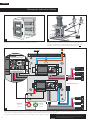
a Disjoncteur
b Alimentations 230 VAC - 12 VDC
c Boîtiers de gestion
d Relais
e Trous de fixation
english
deutsch
a Schutzschalter
b 230 VAC - 12 VDC
c Steuerungskasten
d Relais
e Befestigungslöcher
a Circuit breaker
b 230 VAC - 12 VDC Supplies
c Driving boxes
d Relay
e Fixation holes
Coret d’alimentation pour VBP ms
Supply box for VBP ms
Elektrischer Versorgungsblock für VBP ms
MS
6 x
+
-
n°3n°2
n°1
3 4
2 oors
>
T°
VBP
5 7
-
T
+
-
p
+
-
p
+
-
+
-
p
+
1 2 3 4 5 6 7 8 9 10 11 12
13 14 15 16 17 18 19 20 21 22 23 24
SIEMENS
LOGO! Power
6EP1322-1SH01
N
L1
+ + - -
SIEMENS
LOGO! Power
6EP1322-1SH01
N
L1
+ + - -
O-OFF
N
N
+
-
n°3n°2
n°1
3 4
2 oors
>
T°
VBP
5 7
-
T
+
-
p
+
-
p
+
-
+
-
p
+
1 2 3 4 5 6 7 8 9 10 11 12
13 14 15 16 17 18 19 20 21 22 23 24
e
DCP notice d’installation - installation instructions - montageanleitung
version n.3 (01/2009)
a b c d

2
+
-
n°3n°2
n°1
3 4
2 oors
>
T°
VBP
5 7
-
T
+
-
p
+
-
p
+
-
+
-
p
+
1 2 3 4 5 6 7 8 9 10 11 12
13 14 15 16 17 18 19 20 21 22 23 24
SIEMENS
LOGO! Power
6EP1322-1SH01
N
L1
+ + - -
SIEMENS
LOGO! Power
6EP1322-1SH01
N
L1
+ + - -
O-OFF
N
N
+
-
n°3n°2
n°1
3 4
2 oors
>
T°
VBP
5 7
-
T
+
-
p
+
-
p
+
-
+
-
p
+
1 2 3 4 5 6 7 8 9 10 11 12
13 14 15 16 17 18 19 20 21 22 23 24
+
-
p
+
-
p
+
-
p
+
-
p
+
-
p
+
-
p
230 VAC 5A max
24
T
-
+
230 VAC
+
-
n°3n°2
n°1
3 4
2 oors
>
T°
VBP
5 7
-
T
+
-
p
+
-
p
+
-
+
-
p
+
1 2 3 4 5 6 7 8 9 10 11 12
13 14 15 16 17 18 19 20 21 22 23 24
SIEMENS
LOGO! Power
6EP1322-1SH01
N
L1
+ + - -
O-OFF
N
N
Installation du coret électrique
Raccorder les composants externes au coffret électrique tels qu’indiqué sur le schéma de branchement, en utilisant les passe-câble fournis :
- les ventilateurs / - la sonde de température / - le témoin de défaut ou de fonctionnement / - l’alimentation 230 VAC
Fixer le couvercle du coffret électrique tel qu’indiqué à l’étape suivante.
français
3
Fixer le coffret électrique à un endroit accessible, partiellement
protégé des intempéries (si possible) et proche des ventilateurs, en
perçant les trous de fixation e prévus à cet effet.
IP65
IP65
IP65
IP65
2
Retirer le couvercle du coffret électrique.
1
Sonde de
température
Neutre
Phase
boîtier
étanche
IP65
boîtier
étanche
IP65
boîtier
étanche
IP65
boîtier
étanche
IP65
boîtier
étanche
IP65
boîtier
étanche
IP65
Témoin de défaut
(non fourni)
Témoin
de
fonctionnement
(non fourni)
+
-
n°3n°2
n°1
3 4
2 oors
>
T°
VBP
5 7
-
T
+
-
p
+
-
p
+
-
+
-
p
+
1 2 3 4 5 6 7 8 9 10 11 12
13 14 15 16 17 18 19 20 21 22 23 24
SIEMENS
LOGO! Power
6EP1322-1SH01
N
L1
+ + - -
O-OFF
N
N
VBP
Le diamètre extérieur de tous les câbles doit être
compris entre 5,5 mm et 10 mm afin d’assurer
l’étanchéité du coffret électrique.

3
Mise en route
Traitement des dysfonctionnements
n°3
n°2
n°1
n°
T°
by
CCP
3 4
2 oors
>
5 7
Réglage
2
Signal Signication Action
3 témoins rouges
allumés en continu.
Le nombre de ventilateurs correctement
branchés ne correspond pas à la consigne
renseignée sur le commutateur.
- Déclencher le disjoncteur (OFF)
- Effectuer les corrections éventuelles
(branchements, nombre de ventilateurs renseigné)
- Réenclencher le disjoncteur (ON)
1 témoin rouge
allumé en continu.
Ce ventilateur est en panne et provoque
l’arrêt des autres ventilateurs.
- Déclencher le disjoncteur (OFF)
- Vérifier si aucun obstacle bloque le moteur du ventilateur
- Effectuer les corrections éventuelles (branchements)
- Réenclencher le disjoncteur (ON)
Si le problème persiste, contacter le distributeur.
Enclencher le disjoncteur.
Mise en route
3
Sur chacun des boîtiers connectés, indiquer:
- nombre de ventilateurs connectés
- nombre total de niveaux
n°3
n°2
n°1
n°
T°
by
CCP
3 4
2 oors
>
5 7
Démarrage
4
Tout s’allume quelques secondes.
Témoin vert : allumé,
Témoins rouges : allumage à tour de rôle.
n°3
n°2
n°1
n°
T°
by
CCP
3 4
2 oors
>
5 7
Marche normale
6
Remise en place du couvercle
1
Témoin vert : clignotement lent. Cela signifie que
tout fonctionne correctement. Fermer ensuite le
coffret à l’aide de la poignée et de la clé.
Fixer le couvercle du coffret à l’aide des 4 vis
fournies.
Les pannes non résolues doivent faire l’objet du remplacement du matériel concerné.
n°3
n°2
n°1
n°
T°
by
CCP
3 4
2 oors
>
5 7
Contrôle
5
de 1 à 20 cycles

4
+
-
n°3n°2
n°1
3 4
2 oors
>
T°
VBP
5 7
-
T
+
-
p
+
-
p
+
-
+
-
p
+
1 2 3 4 5 6 7 8 9 10 11 12
13 14 15 16 17 18 19 20 21 22 23 24
SIEMENS
LOGO! Power
6EP1322-1SH01
N
L1
+ + - -
SIEMENS
LOGO! Power
6EP1322-1SH01
N
L1
+ + - -
O-OFF
N
N
+
-
n°3n°2
n°1
3 4
2 oors
>
T°
VBP
5 7
-
T
+
-
p
+
-
p
+
-
+
-
p
+
1 2 3 4 5 6 7 8 9 10 11 12
13 14 15 16 17 18 19 20 21 22 23 24
+
-
p
+
-
p
+
-
p
+
-
p
+
-
p
+
-
p
230 VAC 5A max
24
T
-
+
230 VAC
+
-
n°3n°2
n°1
3 4
2 oors
>
T°
VBP
5 7
-
T
+
-
p
+
-
p
+
-
+
-
p
+
1 2 3 4 5 6 7 8 9 10 11 12
13 14 15 16 17 18 19 20 21 22 23 24
SIEMENS
LOGO! Power
6EP1322-1SH01
N
L1
+ + - -
O-OFF
N
N
+
-
n°3n°2
n°1
3 4
2 oors
>
T°
VBP
5 7
-
T
+
-
p
+
-
p
+
-
+
-
p
+
1 2 3 4 5 6 7 8 9 10 11 12
13 14 15 16 17 18 19 20 21 22 23 24
SIEMENS
LOGO! Power
6EP1322-1SH01
N
L1
+ + - -
O-OFF
N
N
Installation of the electrical box
Connect the external components to the electrical box as indicated on the diagram of connection::
- fans / - temperature sensor / - breakdown indicator or working indicator / - 230 VAC supply
Put back the cover on the electrical box.
english
1
IP65
IP65
IP65
IP65
Breakdown
indicator
(not supplied)
Working
indicator
(not supplied)
Temperature
sensor
Waterproof
box IP65
Waterproof
box IP65
Waterproof
box IP65
Waterproof
box IP65
Waterproof
box IP65
Waterproof
box IP65
Neutral
Phase
3
Remove the cover of the electrical box. Fix the electrical box at an accessible place, partially protected from
bad weather and close to the fans (if possible), by drilling the dedica-
ted fixation holes ( e ).
2
VBP
The external diameter of wires must be between
5,5 mm and 10 mm in order to guarantee the water
tightness of the electrical box.

5
Start-up
Breakdown processing
Signal Meaning Action
3 red test-buttons
uninterrupted lit.
The number of correctly connected fans
does not correspond to the instruction
mentioned on the switch.
- Disconnect the circuit breaker (OFF)
- Carry out the possible corrections
(connections, number of connected fans)
- Reconnect the circuit breaker (ON)
1 red test-button
uninterrupted lit.
This fan is out of order, so the other fans
stop.
- Disconnect the circuit breaker (OFF)
- Check if no obstacle blocks the motor fan
- Carry out the possible corrections (connections)
- Reconnect the circuit breaker (ON)
If the problem continues, please contact the distributor.
The unsolved breakdowns must involve the replacement of the concerned material.
n°3
n°2
n°1
n°
T°
by
CCP
3 4
2 oors
>
5 7
Adjustment
2
Engage the circuit breaker.
Start-up
3
On both control boxes, set the indications of:
- number of connected fans
- total number of floors / levels
n°3
n°2
n°1
n°
T°
by
CCP
3 4
2 oors
>
5 7
Starting
4
Every lights are lighting a few seconds.
Green test-button : lit,
Red test button : lit in rotation.
n°3
n°2
n°1
n°
T°
by
CCP
3 4
2 oors
>
5 7
Working
6
Fixing of the cover
1
Green test-button: slow intermittent signal.
This means that the system is working normally.
Then close the door by the mean of the handle
and the key.
Fix the cover by the mean of 4 screws
(supplied).
n°3
n°2
n°1
n°
T°
by
CCP
3 4
2 oors
>
5 7
Control
5
from 1 to 20 cycles

6
+
-
n°3n°2
n°1
3 4
2 oors
>
T°
VBP
5 7
-
T
+
-
p
+
-
p
+
-
+
-
p
+
1 2 3 4 5 6 7 8 9 10 11 12
13 14 15 16 17 18 19 20 21 22 23 24
SIEMENS
LOGO! Power
6EP1322-1SH01
N
L1
+ + - -
SIEMENS
LOGO! Power
6EP1322-1SH01
N
L1
+ + - -
O-OFF
N
N
+
-
n°3n°2
n°1
3 4
2 oors
>
T°
VBP
5 7
-
T
+
-
p
+
-
p
+
-
+
-
p
+
1 2 3 4 5 6 7 8 9 10 11 12
13 14 15 16 17 18 19 20 21 22 23 24
+
-
p
+
-
p
+
-
p
+
-
p
+
-
p
+
-
p
230 VAC 5A max
24
T
-
+
230 VAC
IP65
IP65
IP65
IP65
Montage des elektrischen Gehäuse
Entfernen Sie den vorderen Deckel des elektrichen Gehäuses.
Schliessen Sie die externen Komponente an Gehäuse an, wie auf dem Anschlussplan erwähnt, dank der gelieferten Kabeldurchführungen:
- die Lüfter / der Temperaturmessgerät / das Defektlicht bzw Laufslicht / 230 VAC Stromversorgung.
Den Deckel des elektrischen Gehäuses wie beim nächsten Schritt erwähnt befestigen.
deutsch
3
1
Befestigen Sie das elektrishe Gehäuse an einem zugänglichen Ort,
teilweise vor Unwetter geschützt (wenn möglich) und in der Nähe
der Lüfter, mit den dazu vorgesehenen Befestigungslöcher e.
2
Defektlicht
(nicht mit
geliefert)
Laufslicht
(nicht mit
geliefert)
Temperaturmessgerät
Neutral
Phase
Dichtes
Gehaüser IP65
Dichtes
Gehaüser IP65
Dichtes
Gehaüser IP65
Dichtes
Gehaüser IP65
Dichtes
Gehaüser IP65
Dichtes
Gehaüser IP65
+
-
n°3n°2
n°1
3 4
2 oors
>
T°
VBP
5 7
-
T
+
-
p
+
-
p
+
-
+
-
p
+
1 2 3 4 5 6 7 8 9 10 11 12
13 14 15 16 17 18 19 20 21 22 23 24
SIEMENS
LOGO! Power
6EP1322-1SH01
N
L1
+ + - -
O-OFF
N
N
+
-
n°3n°2
n°1
3 4
2 oors
>
T°
VBP
5 7
-
T
+
-
p
+
-
p
+
-
+
-
p
+
1 2 3 4 5 6 7 8 9 10 11 12
13 14 15 16 17 18 19 20 21 22 23 24
SIEMENS
LOGO! Power
6EP1322-1SH01
N
L1
+ + - -
O-OFF
N
N
VBP
Um die Dichtheit des Schaltschranks zu sichern, soll
das Aussendurchmesser von aller Kabel zwischen
5,5 und 10 mm beintragen sein.

7
Einschaltung
Funktionsstörungenbehandlung
Signal Bedeutung Lösung
3 kontinuierliche
brennende rote
Kontrolllämpchen.
Die Anzahl der Ventilatoren ents-
pricht die Gaben des Kommutators
nicht.
-Schalten Sie den Schutzschalter aus (OFF)
-Führen Sie die eventuelle Korrekturen durch
(Verbindungen,Anzahl der angegebenen Ventilatoren)
-Schalten Sie den Schutzschalter wieder ein (ON)
1 kontinuierliche
brennende rote
Kontrolllämpchen.
Dieser Ventilator funktionniert
nicht und führt zum Stillstand
der anderen Ventilatoren.
-Schalten Sie den Schutzschalter aus (OFF)
- Prüfen Sie, dass kein Hinderniss den Ventilatormotor behindert
-Führen Sie die eventuelle Korrekturen (Verbindungen) durch
-Schalten Sie den Schutzschalter wieder ein (ON)
Wenn das Problem andauert, nehmen Sie mit Ihrem Händler Kontakt auf
Die nicht geklärten Pannen müssen zum Ersetzten des betroffenes Objektes führen.
n°3
n°2
n°1
n°
T°
by
CCP
3 4
2 oors
>
5 7
Einstellung
2
Schalten Sie den Schutzschalter ein.
Einschaltung
3
Prüfen Sie folgende Angaben :
- Zahl der verbundenen Ventilatoren
- Zahl der Stufen
n°3
n°2
n°1
n°
T°
by
CCP
3 4
2 oors
>
5 7
Start
4
Alles leuchtet ein paar Sekunden.
- Grünes Kontrolllämpchen : brennend,
- Rote Kontrolllämpchen : abweschelndes Brennen.
n°3
n°2
n°1
n°
T°
by
CCP
3 4
2 oors
>
5 7
Normales Betrieb
6
Den Deckel wieder einstellen
1
Grünes LED: langsames Blinken. Es bedautet
dass alles richtig funktionniert. Danach das
Gehäuse mit Schlüssel und Griff schliessen.
Den Deckel mit den 4 gelieferten Schrauben
befestigen.
n°3
n°2
n°1
n°
T°
by
CCP
3 4
2 oors
>
5 7
Kontrolle
5
1 bis 20 Zyklen

TF4229_C
AERECO S.A
9, allée du clos des charmes
COLLEGIEN
77 615 Marne la Vallée cédex 3
FRANCE
www.aereco.com
-
 1
1
-
 2
2
-
 3
3
-
 4
4
-
 5
5
-
 6
6
-
 7
7
-
 8
8


in anderen Sprachen
- English: Aereco VBP Installation guide
- français: Aereco VBP Guide d'installation
Verwandte Artikel
Andere Dokumente
-
Eurotherm 900 Bedienungsanleitung
-
 Sim-Wings Mega Airport Amsterdam Schiphol Bedienungsanleitung
-
CP Electronics EBDHS-AD High Bay Presence Detectors Installationsanleitung
-
WineMate 8500HZD Benutzerhandbuch
-
Iomega eGo 34889 Schnellstartanleitung
-
Briteq LDP-FLOOD80-WW Bedienungsanleitung
-
SEBSON IR_OUT_E Benutzerhandbuch
-
Chauvet MAVERICK Benutzerhandbuch
