Pepperl+Fuchs VLM350-F280-R4-1001 Bedienungsanleitung
- Typ
- Bedienungsanleitung

alle Maße in mm
DimensionsAbmessungen
Technische Daten Technical data
Elektrischer Anschluss Electrical connection Adressen/Addresses
Sicherheitshinweise:
•Vor der Inbetriebnahme Betriebsanleitung lesen
• Anschluss, Montage und Einstellung nur durch Fachpersonal
• Kein Sicherheitsbauteil gemäß EU-Maschinenrichtlinie
Security Instructions:
• Read the operating instructions before attempting commissioning
• Installation, connection and adjustments should only be undertaken by specialist personnel
• Not a safety component in accordance with the EU Machinery Directive
all dimensions in mm
www.pepperl-fuchs.com
Pepperl+Fuchs GmbH
68301 Mannheim · Germany
Tel. +49 621 776-4411
Fax +49 621 776-27-4411
E-mail: fa-inf[email protected]
Worldwide Headquarters
Pepperl+Fuchs GmbH · Mannheim · Germany
E-mail: fa-inf[email protected]
USA Headquarters
Pepperl+Fuchs Inc. · Twinsburg · USA
E-mail: fa-inf[email protected]
Asia Pacific Headquarters
Pepperl+Fuchs Pte Ltd · Singapore
E-mail: fa-inf[email protected]
Company Registration No. 199003130E
38 12 M4
55
85
99.1
32 48
5
8 15.35
M4
20
A
A
14
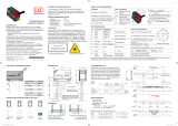
Laserlichtschnitt-Sensor
Laser light sensor
VLM350-F280-R4-1001
Allgemeine Daten
Messbereich X = 40 ... 160 mm ; Z = 60 ... 350 mm
Lichtsender Laserdiode
Lichtart Laser rot + Integrierter LED-Blitz rot 650 nm
Laserkenndaten
Hinweis SICHTBARE LASERSTRAHLUNG , NICHT IN DEN STRAHL BLICKEN
NICHT DIREKT MIT OPTISCHEN INSTRUMENTEN BETRACHTEN
Laserklasse 1
Wellenlänge Messlaser: 660 nm
Impulsdauer Messlaser: 0,5 ms
Maximale optische Ausgangsleistung Messlaser: 15 mW
Laserüberwachung Das Sicherheitssystem schaltet den Laser bei zu hohem Laserstrom ab
Scanrate 10 s-1
Auflösung X > 0,44 mm ; Z > 0,4 mm
bei 60 mm Leseabstand
Kenndaten funktionale Sicherheit
MTTFd 20 a
Gebrauchsdauer (TM) 10 a
Diagnosedeckungsgrad (DC) 0 %
Anzeigen/Bedienelemente
Betriebsanzeige LED grün
Diagnoseanzeige LED gelb / rot
Funktionsanzeige Trigger: LED gelb ; Objekt erfasst : LED rot / grün
Bedienelemente 2 Taster
Elektrische Daten
Betriebsspannung UB24 V ± 20 % , PELV
Leerlaufstrom I0max. 250 mA
Leistungsaufnahme P0max. 6 W , Ausgänge ohne Last
Schnittstelle
Schnittstellentyp RS 485-Schnittstelle
Physikalisch Abschlusswiderstand zuschaltbar
Protokoll Binär-Code
Übertragungsrate 38400 ... 230400 Bit/s
Eingang
Eingangsspannung 24 V
Anzahl/Typ Externe Triggerung + 1 Eingang
Schaltschwelle low: < 2,5 V, high: > 8 V
Ausgang
Anzahl/Typ 2 digitale Ausgänge
Schaltungsart PNP
Schaltspannung 24 V
Schaltstrom 150 mA je Ausgang
Umgebungsbedingungen
Betriebstemperatur -20 ... 45 °C (-4 ... 113 °F) , (nicht kondensierend; Eisbildung an der Frontscheibe vermeiden!)
Lagertemperatur -20 ... 70 °C (-4 ... 158 °F)
Mechanische Daten
Schutzart IP67
Anschluss Gerätestecker M12 x 1, 8-polig ( Versorgung + RS485 + Ein-/Ausgänge ) ; 90° drehbar ; Erdung :
Erdungsclip für System PCV
Material
Gehäuse PC/ABS
Lichtaustritt Kunststoffscheibe
Masse ca. 125 g
Anzugsmoment Befestigungsschrauben
≤
2 Nm
Allgemeine Informationen
Hinweis Sicherheitshinweis:
- Lesen Sie vor der Inbetriebnahme die Betriebsanleitung
- Anschluss, Montage und Einstellung nur durch Fachpersonal
- Kein Sicherheitsbauteil gemäß EU-Maschinenrichtlinie
Normen- und Richtlinienkonformität
Normenkonformität
Störfestigkeit EN 61000-6-2:2005
Störaussendung EN 61000-6-4:2007/A1:2011
Schutzart EN 60529
Schock- und Stoßfestigkeit EN 60068-2-27:2009
Laserklasse IEC 60825-1:2007
38 12 M4
55
85
99.1
32 48
5
8 15.35
M4
20
A
A
14
02/04/2019
Date
General specifications
Measurement range X = 40 ... 160 mm ; Z = 60 ... 350 mm
Light source laser diode
Light type red laser + Integrated LED lightning red 650 nm
Laser nominal ratings
Note VISIBLE LASER RADIATION , DO NOT STARE INTO BEAM
DO NOT VIEW DIRECTLY WITH OPTICAL INSTRUMENTS
Laser class 1
Wave length Measurement laser: 660 nm
Pulse length Measurement laser: 0.5 ms
Maximum optical power output Measurement laser: 15 mW
Laser monitoring The safety system switches off the laser when the laser current is too high
Scan rate 10 s-1
Resolution X > 0.44 mm ; Z > 0.4 mm
at 60 mm read distance
Functional safety related parameters
MTTFd 20 a
Mission Time (TM) 10 a
Diagnostic Coverage (DC) 0 %
Indicators/operating means
Operation indicator LED green
Diagnostics indicator LED yellow / red
Function indicator Trigger: LED yellow ; object detected : LED red / green
Control elements 2 push-buttons
Electrical specifications
Operating voltage UB24 V ± 20 % , PELV
No-load supply current I0max. 250 mA
Power consumption P0max. 6 W , Outputs without load
Interface
Interface type RS 485 interface
Physical Switchable terminal resistor
Protocol binary code
Transfer rate 38400 ... 230400 Bit/s
Input
Input voltage 24 V
Number/Type External triggering + 1 Input
Switching threshold low: < 2.5 V, high: > 8 V
Output
Number/Type 2 digital outputs
Switching type PNP
Switching voltage 24 V
Switching current 150 mA each output
Ambient conditions
Operating temperature -20 ... 45 °C (-4 ... 113 °F) , (noncondensing; prevent icing on the lens!)
Storage temperature -20 ... 70 °C (-4 ... 158 °F)
Mechanical specifications
Degree of protection IP67
Connection 8-pin, M12 x 1 connector ( supply + RS485 + Inputs/Outputs ) ; can be rotated 90° ; Grounding :
Grounding clip for PCV system
Material
Housing PC/ABS
Optical face Plastic pane
Mass approx. 125 g
Tightening torque, fastening screws
≤
2 Nm
General information
Note Security Instructions:
- Read the operating instructions before attempting commissioning
- Installation, connection and adjustments should only be undertaken by specialist
personnel - Not a safety component in accordance with the EU Machinery Directive
Compliance with standards and directives
Standard conformity
Noise immunity EN 61000-6-2:2005
Emitted interference EN 61000-6-4:2007/A1:2011
Degree of protection EN 60529
Shock and impact resistance EN 60068-2-27:2009
1
4
6
7
8
5
3
2
Pin Signal
1 IN Trigger
2 +UB
3 Data+ RS-485
4 Data- RS-485
5 Teach
6 Good
7 GND
8 Bad
1
4
6
7
8
5
3
2
Pin Signal
1 IN Trigger
2 +UB
3 Data+ RS-485
4 Data- RS-485
5 Teach
6 Good
7 GND
8 Bad
DIN A3 ->
Part. 284586- 45-5296A
Doc.

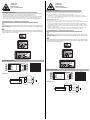
LASERLICHT
LASER LIGHT
LASER KLASSE 1
CLASS 1 LASER PRODUCT
• Die Bestrahlung kann zu Irritationen gerade bei dunkler Umgebung führen. Nicht auf Menschen richten!
•Wartung und Reparaturen nur von autorisiertem Servicepersonal durchführen lassen!
• Das Gerät ist so anzubringen, dass die Warnhinweise deutlich sichtbar und lesbar sind.
• Der Warnhinweis liegt dem Gerät bei und ist in unmittelbarer Nähe zum Gerät gut sichtbar anzubringen.
• Vorsicht: Wenn andere als die hier angegebenen Bedienungs- oder Justiereinrichtungen benutzt oder
andere Verfahrensweisen ausgeführt werden, kann dies zu gefährlicher Strahlungseinwirkung führen.
LASER Warnhinweise nach IEC 60825-1:2007, 21CFR 1040.10 und 1040.11 (except for deviations pursuant to Laser
Notice No. 50, dated 6-24-07) konnten nicht am Gerät befestigt werden. Die Warnhinweise sind selbstklebend und lie-
gen der Verpackung bei.
LASER hazard warning labels required by IEC 60825-1:2007, 21CFR 1040.10 and 1040.11 (except for deviations pur-
suant to Laser Notice No. 50, dated 6-24-07) could not be affixed to the product, but are supplied with the product as
self-adhesive labels in the product packaging.
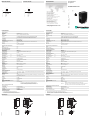
Messbereich
Laserhinweis Laserklasse 1
Anzeigen/Bedienelement
LASER Warnhinweise / LASER hazard warning labels
grün/rot
grün/gelb
grün/rot
grün/gelb
rot
grün
gelb
gelb
1 Ready
2 Match 3/4
3 Result
4 Match 1/2
5 Diagnose
6 Power
7 Teach
8 Trigger
1
2
3
4
5
6
7
8
READY
READY
MATCH 1/2
MATCH 1/2
MATCH 3/4
MATCH 3/4
RESULT
RESULT
DIAGNOSE
DIAGNOSE
TRIGGER
TRIGGER
POWER
POWER
TEACH
TEACH
Anfang
Messbereich Messbereich Z
Erfassungsbereich
Xmax
Xmin
-/+
LASERLICHT
LASER LIGHT
LASER KLASSE 1
CLASS 1 LASER PRODUCT
• The irradiation can lead to irritation especially in a dark environment. Do not point at people!
• Maintenance and repairs should only be carried out by authorized service personnel!
• Attach the device so that the warning is clearly visible and readable.
•The warning accompanies the device and should be attached in immediate proximity to the device.
•Caution – Use of controls or adjustments or performance of procedures other than those specified herein
may result in hazardous radiation exposure.
• L’irradiation peut entraîner des irritations dans un environnement sombre. Ne pas orienter vers les person-
nes !
• L’entretien et les réparations doivent être réalisés exclusivement par le personnel de service autorisé !
• L’appareil doit être installé de manière à ce que les mises en garde soient clairement visibles et lisibles.
• Les instructions de mise en garde sont jointes à l’appareil et doivent être installées à proximité directe de
l'appareil de manière visible.
• Attention : Si d’autres dispositifs de commande ou de réglage sont utilisés que ceux indiqués ici, ou si
d’autres procédures sont exécutées, cela peut entraîner un effet préjudiciable du rayonnement.
LASER Warnhinweise nach IEC 60825-1:2007, 21CFR 1040.10 und 1040.11 (except for deviations pursuant to Laser
Notice No. 50, dated 6-24-07) konnten nicht am Gerät befestigt werden. Die Warnhinweise sind selbstklebend und lie-
gen der Verpackung bei.
LASER hazard warning labels required by IEC 60825-1:2007, 21CFR 1040.10 and 1040.11 (except for deviations pur-
suant to Laser Notice No. 50, dated 6-24-07) could not be affixed to the product, but are supplied with the product as
self-adhesive labels in the product packaging.
Measuring range
Laser notice laser class 1
Consigne laser classe 1
Indicating/Operating
LASER Warnhinweise / LASER hazard warning labels
green/red
green/yellow
green/red
green/yellow
red
green
yellow
yellow
1 Ready
2 Match 3/4
3 Result
4 Match 1/2
5 Diagnose
6 Power
7 Teach
8 Trigger
1
2
3
4
5
6
7
8
READY
READY
MATCH 1/2
MATCH 1/2
MATCH 3/4
MATCH 3/4
RESULT
RESULT
DIAGNOSE
DIAGNOSE
TRIGGER
TRIGGER
POWER
POWER
TEACH
TEACH
Start
measuring range
Measuring
range Z
Sensing range
Xmax
Xmin
-/+
-
 1
1
-
 2
2


Pepperl+Fuchs VLM350-F280-R4-1001 Bedienungsanleitung
- Typ
- Bedienungsanleitung
in anderen Sprachen
Verwandte Artikel
-
Pepperl+Fuchs VLD700-F280-2E2-1000 Bedienungsanleitung
-
-
-
-
-
-
-
-
-