ESAB A6 TFD1 / TFD2 / TGD1 Benutzerhandbuch
- Kategorie
- Spielzeuge
- Typ
- Benutzerhandbuch

443 401 --002 9510 Valid from Machine no 452 XXX--XXXX
A6 TFD1/TFD2/
TGD1
Auto matic welding machine
Schweißautomat
Appareil de soudage automatique
Lasautomaat
Operating manual
Bedienungsanleitung
Manuel de l’opérateur
Gebruikershandboek

SAFETY 2..............................................
TECHNICAL DESCRIPTION 3.............................
INSTALLATION 4........................................
OPERATION 7..........................................
MAINTENANCE 10........................................
TROUBLESHOOTING 11..................................
CONNECTION INSTRUCTIONS FOR PEG1 AND A6 VEC 12..
SICHERHEIT 14..........................................
TECHNISCHE BESCHREIBUNG 15.........................
INSTALLATION 16........................................
BETRIEB 19..............................................
WARTUNG 22............................................
FEHLERSUCHE 23.......................................
ANSCHLUSSANLEITUNG FÜR PEG1 UND A6 VEC 24.......
SÉCURITÉ 26............................................
DESCRIPTION TECHNIQUE 27............................
INSTALLATION 28........................................
FONCTIONNEMENT 31...................................
ENTRETIEN 34...........................................
RECHERCHE DE PANNES 35..............................
INSTRUCTIONS DE BRANCHEMENT POUR PEG1 ET A6 VEC 36
VEILIGHEID 38...........................................
TECHNISCHE BESCHRIJVING 39..........................
INSTALLATIE 40..........................................
GEBRUIK 43.............................................
ONDERHOUD 46.........................................
STORINGZOEKEN 47.....................................
INSCHAKELINSTRUCTIES VOOR PEG1 EN A6 VEC 48......
DIMENSION DRAWING - MASSBILD - COTES
D’ENCOMBREMENT - MAATSCHE TS 49..............
DIAGRAM - SCHALTPLAN - SCHÉMA - SCHEMA 51.........
WEAR COMPONENTS - VERSCHLEISSTEILE -
PIÈCES D’USURE - SLIJTAGEONDERDELEN 53......
Rights reserved to alter specifications without notice.
Änderungen vorbehalten.
Sous réserve de modifications sans avis préalable.
Recht op wijzigingen zonder voorafgaande mededeling voorbehouden.

-- 1 --
mmvarnea
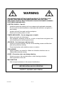
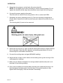
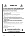
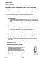
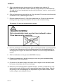
WARNING
ARC WELDING AND CUTTING CAN BE INJURIOUS TO YOURSELF AND
OTHERS. TAKE PRECAUTIONS WHEN WELDING. ASK FOR YOUR
EMPLOYER’S SAFETY PRACTICES WHICH SHOULD BE BASED ON MANU--
FACTURER’S HAZARD DATA.
ELECTRIC SHOCK -- Can kill
S Install and earth the welding unit in accordance with applicable standards.
S Do not touch live electrical parts or electrodes with bare skin, wet gloves or
wet cloth ing.
S Insulate yourself from earth and the workpiece.
S Ensure your working stance is safe.
FUMES AND GASES -- Can be dangerous to health
S Keep your head out of the fumes.
S Use ventilation, extraction at the arc, or both, to keep fumes and gases from
your breathing zone and the general area.
ARC RAYS -- Can injure eyes and b u rn skin
S Protect your eyes and body. Use the correct welding screen and filter lens
and wear protective clothing.
S Protect bystanders with suitable screens or curtains.
FIRE HAZARD
S Sparks (spatter) can cause fire. Make sure therefore that there are no
inflammable materials nearby.
NOISE -- Excessive no ise can damage hearing
S Protect your ears. Use ear defenders or other hearing protection.
S Warn bystanders of the risk.
MALFUNCTION
S Call for expert assistance in the event of malfunction.
READ AND UNDERSTAND THE OPERATING MANUAL
BEFORE INSTALLING OR OPERATING.
PROTECT YOURSELF AND OTHERS!

SAFETY
-- 2 --
df00f1ea
SAFETY
Users of ESAB automatic welding machines have ultimate responsibility for ensuring
that anyone who works on or near the equipment observes all the relevant safety
precautions.
The following recommendations should be observed in addition to the standard re-
gulations that apply to the work place.
All work must be carried out according to the specified instructions by personnel who
are thoroughly familiar with the operation of the welding machine.
Incorrect or unintentional operation of the equipment may lead to a hazardous situ -
ation which can result in injury to the operator and damage to the equipment.
1. Anyone who uses the automatic welding machine must be familiar with:
S its operation
S the location of emergency stops
S its function
S relevant safety precautions
To make this easier each switch, pushbutton or potentiometer is marked with a
symbol or text that indicates its function when activated.
2. The operator must ensure that:
S no unauthorized person is stationed within the working area of the machine
when it is started up.
S that no--one is in a hazardous position when the carriage or slide mechan-
isms are operated.
3. The work place must:
S be clear of mechanical components, tools, or other obstructions that could
prevent the operator from moving freely within the working area.
S be organized so that there is free access to the emergency stop.
4. Personal safety equipment
S Always wear recommended personal safety equipment, such as safety
glasses, flame--proof clothing, safety gloves.
S Do not wear loose--fitting items, such as scarves, bracelets, etc., which could
become trapped.
5. General precautions
Live electrical components are normally shielded from accidental contact.
S Make sure the return cable is connected securely.
S Work on high voltage components may only be carried out by a qualified
electrician.
S Appropriate fire extinguishing equipment must be clearly marked and close
at hand.
S Lubrication and maintenance must not be carried out on the equipment dur-
ing its operation.

TECHNICAL DESCRIPTION
-- 3 --
dfa4d1ea
TECHNICAL DESCRIPTION
The A6 TFD1 automatic welding machine is mounted on a tractor carriage and is de -
signed for submerged arc welding of butt and fillet joints (using AC or DC).
The A6 TFD2 automatic welding machinewith its twin welding heads is mounted on a
tractor carriage and is designed for submerged arc welding of butt joints (using AC
or DC).
The A6 TGD1 automatic welding machineis mounted on a tractor carriage and is de-
signed for MIG/M AG welding o f butt and fillet joints (using DC).
The horizontal and vertical positions of the welding head can be adjusted using a
cross slide. The angular position is adjusted using a rotary slide.
All other applications are prohibited.
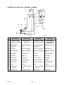
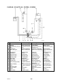
TECHNICAL DATA
A6 TFD1 A6 TFD2 A6 TGD1
Rating 1500 A DC/AC 1500 A DC/AC 600 A DC
Electrode size
solid single wire 3,0--6,0 mm 3,0--6,0 mm 1,0--2,4 mm
tube wire 1,6--3,2 mm
twin wire 2x2,0--2x3,0
Wire feed speed, max 4,2 m/min 4,2 m/min 17,5 m/min
T ravel speed, max. 2,5 m/min 2,5 m/min 2,5 m/min
Electrode weight, max 30 kg 30 kg 30 kg
Flux container volume
(Must not be filled with preheated flux)
10 l 10 l
Weight (excl. wire and flux) 110 kg 158 kg 100 kg
Brake hub braking torque 1,5 Nm 1,5 Nm 1,5 Nm
T ransverse inclination, max 25_ 25_ 25_
Supply voltage 42 V AC 42 V AC 42 V AC
Continuous A--weighted noise pressure 68 dB 68 dB 83 dB
See dimension drawing on page 49 and on page 50.

aza5dp17
INSTALLATION
-- 4 --
dfa4i1ea
INSTALLATION
Connecting the automatic welding machine welding power source
1. Set the machine for butt or fillet welding as shown on the dimension drawing on
page 49.
2. A6 VEC wire feed motor, see operators’ manual 443 393.
3. Control unit PEG1, see operators’ manual 443 392.
4. Connect the cables according to the diagram on page 51 and page 52.
S Rectifier:
S Connect control cable (08) for the A6 TFD1 or (15) for the A6 TGD1 be-
tween the power source (01) and the control unit PEG1 (02).
S Connect the cable with the connecting lugs (07) or (08) between the
power source (01) and the shunt.
S Alternating current:
S Connect control cable (08) between the filler wire unit (11) and the PEG1
control unit (02).
S Connect the filler wire unit ( 11) to the power source ( 10) .
S Connect the welding cable (07) between the power source (10) and
shunt.
S Connect the return cable between the power source (01, 10) and the work--
piece.
S Connect the measuring cable (09) or (16) between the work piece and power
source (01,10) or between the work piece and the PEG1 control unit (02)
(e.g. if a power source of a different make is used).
S Connect the A6 VEC motor and gearbox to the PEG1 control unit (02).
Check that the PEG1 control unit is connected as shown in the table on page 12
and that the gear ratio and motor speed match the values given there.
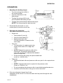
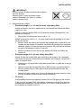
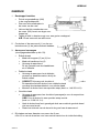
Installing filler wire.
Replacing a wire r eel.
S Removethewirereelfromthebrakehub(2)
and remove the end plate (3).
S Place the coil of wire (1) on the reel and fit
the end plate (3).
S Fit the wire reel or disposable reel on the
brake hub (2).
NOTE the position of the locking stud.

INSTALLATION
-- 5 --
dfa4i1ea
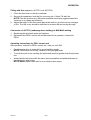
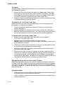
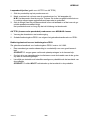
IMPORTANT!
To prevent the wire bobbin slipping
off the brake hub:
Lock the bobbin in place using the red knob,
as shown on the label (see drawing on right)
positioned next to the brake hub.
5. Contact tip equipment
S Single wire 1.6 -- 2.5 mm (4.0 mm). Light duty (D20)
For use in restricted spaces, etc., with wire diameters up to 4.0 mm.
Use contact tube D20 with contact tip (M12 thread), see table on page 55.
S Tighten the contact tip using a no. 10 spanner to ensure good electrical
contact.
For smaller wire diameters, 1.6 -- 2.5 mm, use a guide tube and separate fine
wire straightener.
S F it the clamp for the guide tube to the M12 hole normally used for the
fixed straightening roller on the standard wire straightener. The guide
tube should bottom against the contact tip. Trim the length so that there
is about a 5 mm gap between the wire feed roller and the end of the
tube.
S Install the fine wire straightener on top of the clamp for the wire straigh-
tener unit.
S Single wire 3.0 -- 6.0 mm. Heavy duty (D35)
Use contact tube D35 with contact jaws. See also the remarks concerning
the use of contact tube D20 for wires up to 4.0 mm in diameter in restricted
spaces.
S Use the standard wire straightener unit for the A6, consisting of one fixed
and one adjustable roller.
S Install the contact jaws using the M5 bolts supplied, fitting one half of the
contact jaws in the fixed contact tube and the o ther in the loose half of
the split contact tube.
S Install the loose half and contact jaw in position and tighten the pressure
screw to ensure good electrical contact between the contact jaw and the
electrode.
S Tube wire
Either the D20 or D35 contact tubes can be used for tube electrode.
If contact jaws (D35) are used only moderate pressure should be applied to
them to prevent deforming the tube wire. Make sure that good contact is ob-
tained with the wire.

INSTALLATION
-- 6 --
dfa4i1ea
S Twin wire
Always use the D35 contact tube for twin wire, with a guide tube and separ-
ate wire straightener.
S F it the clamp for the guide tube to the M12 hole normally used for the
fixed straightening roller on the standard wire straightener. The guide
tube should bottom against the contact jaw (Heavy Twin) or against the
adapter for the contact tip (Light Twin).
S Trim the length so that there is about a 5 mm gap between the wire feed
roller and the end of the tube.
Twin wire 2x1.2 -- 2x2.0 mm, Light Twin:
Use (2) contact tips with M6 threads. For wire diameters see table on page
55.
S Tighten the contact tips well to ensure good electrical contact.
S F it the M5 adapter for the M6 contact tips in the fixed half of the split
contact tube. The pressure screw and the loose half of the contact tube
are not necessary for this application.
Twin wire 2x2.0 -- 2x3.0 mm, Heavy Twin :
S Use Twin contact jaws for large diameter wires
(2x2,0 mm, see also Light Twin).
S Fit the contact jaws using the M5 bolts supplied for the purpose.
NOTE! Fit the contact jaw half with the projection in the fixed section of
the contact tube.
S Remove the loose half of the contact tube when installing new wire by
undoing the pressure screw.
S F eed out the wire and guide it through the groove in the fixed half of the
contact jaws (projection).
S Unscrew the M5 bolt for the contact jaw and fit the loose half using an
M8 allen bolt, so that the half of the contact jaw with the projection and
the opposing half surround the wires. The loose section of the contact
tube is then bolted in place using the M5 bolts to provide good contact.
S Adjustment of wires for Twinarc welding:
Adjust the wires in the joint to give the optimum weld results by twisting the
contact tube. The wires can be rotated so that they are in line with the joint or
at any angle up to 90_ to the joint, i.e., one wire each side of the joint.
S Tandem welding
S The distance between the first wire and the second must not be so large
that the slag solidifies before the following wire reaches it.
S Make sure there is a good covering of flux between the first and second
wire.

aza5dp08
dfa3d002
OPERATION
-- 7 --
dfa4o1ea
OPERATION
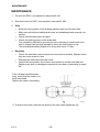
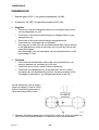
1. Adjusting the braking torque:
S Turn the locking knob (006) to
the locked position.
S Insert a screwdriver in the
hub springs.
S Turning the springs (002) clock-
wise increases the braking torque.
S Turning them anticlockwise reduces the torque.
NOTE! Turn the springs the same amount.
2. Check that the feed roller (1) and
contact jaws (4) are the correct size.
3. Changing the feed roller
(see wear components on page 53).
S Single wire
S Undo knobs (5) and (6).
S Undo the hand wheel (2).
S Replace the feed roller.
Thewirediameterismarkedonthe
feed rollers.
S Twin wire
S T he procedure for replacing twin wire
rollers is the same as for single wire
rollers.
S NOTE! Replace the pressure roller at the
same time. The special spherical pres -
sure roller for twin wire replaces the standard
roller for single wire.
S Fit the pressure roller using the special shaft stud
(order no. 146 253--001).
S Tube wire
S Replace the feed roller and pressure roller as a pair for the required wire
size.
S NOTE! A special shaft stud is required for the pressure roller
(order no. 2129 011--01).
S Do not overtighten the pressure roller to avoid deforming the tube wire.
S Insert the end of the wire in the groove in the feed roller.
4. If the wire diameter is larger than 2 mm:
straighten out the first 0.5 m of the wire and feed it by hand through the wire
straightener.

OPERATION
-- 8 --
dfa4o1ea
5. Adjust the wire pressure on the feed roller using knob (6).
NOTE: Do not tighten more than necessary to ensure uniform feeding. Do not
tighten the knob (6) all the way, there should be some travel left in the spring.
6. Connect the power supply to the mains.
Feed the wire out about 30 mm using switch A 02 on control unit PEG1.
7. Straighten the wire by adjusting knob (5). Fine wire should be straight about
25 mm after it leaves the contact tip and heavy wire about 45 mm after the con-
tact tip.
The securing bolt (3) must not be removed.
WARNING!
Rotating parts can cause injury, take great care.
8. Select the wire and flux (or gas) so that the weld metal analysis roughly matches
that of the plate. Select the wire diameter and welding parameters as recom-
mended by the consumable manufacturer.
9. Connect the cooling water and gas (MIG/MAG welding).
10. Adjust the flux nozzle so that it does not bend and gives a good covering of flux
(submerged arc welding).
11. Make sure the distance between the carriage wheels and the weld joint is not
less than 50 mm during welding.
12. If the control handles are moved make sure they are screwed all the way in so
that the tapered surfaces meet. Use the holes in the guide handles to help
tighten them thoroughly. Clean the threads if necessary.

OPERATION
-- 9 --
dfa4o1ea
Filling with flux (appliestoA6TFD1ochA6TFD2)
1. Close the flux valve on the flux container.
2. Remove the separator from the flux recovery unit, if fitted. Fill with flux.
NOTE! The flux must be dry. Whenever possible avoid using agglomerated flux
outdoors or in a damp environment.
3. Adjust the height of the flux nozzle above the weld, to give the correct coverage
of flux. The flux cover should be sufficient to prevent the arc burning through.
Conversion of A6 TFD1 (submerged arc welding) to MIG/MAG welding
1. Replacing the wire feed motor and gearbox.
2. Reconnect the PEG1 control unit as described in the operators’ manual for
PEG1.
Operating instructions for PEG1 control unit
See operators’ manual for PEG1 control unit, order no. 443 392.
S Careful preparation is essential for good welding results.
NOTE! There m ust not be any variation in the joint gap width.
S To avoid the risk of hot cracking the weld width must be greater than the penetra-
tion.
S Always weld a test piece with the same joint preparation and plate thickness as
the production work piece.
NOTE! Never makeatestweldonaproductionworkpiece.

MAINTENANCE
-- 1 0 --
dfa4m1ea
MAINTENANCE
1. Control unit PEG1, see operators’ manual 443 392.
2. Wire feed motor A6 VEC, see operators’ manual 443 393.
3. Daily
S Keep the moving parts of the welding machine free from flux and dust.
S Make sure all electrical cables and hoses are undamaged and properly con-
nected.
S Check that all bolted joints are tight.
S Check the braking torque of the brake hub.
This should be sufficient to prevent the reel continuing to rotate when wire
feed is stopped but not high enough to cause the feed rollers to slip.
Recommended braking torque for a 30 kg wire reel is 1.5 Nm.
4. Regularly
S Check the wire feed motor brushes once every three months. Replace when
they are worn down to 6 mm.
S Examine the slides and lubricate if stiff.
S Inspect the wire guides, drive rollers and contact tip on the wire feed unit.
Replace any worn or damaged components, see wear components on page
53.
If the carriage travel becomes
jerky, check that the chain is cor-
rectly tensioned.
Tension the chain if necessary.
dfa4b001
*1 To tension the chain undo the nut and turn the cam, then tighten the nut.

TROUBLESHOOTING
-- 1 1 --
dfa3f1ea
TROUBLESHOOTING
Equipment
S Manual for control box PEG1, order no. 443 392.
S Manual for motor with gear A6 VEC, order no. 443 393.
Check
S that the welding power supply is connected for the correct mains
voltage
S that all three phases are giving the correct voltage
(phase sequence not important)
S that the welding cables and connections to them are not damaged
S that the controls are in the right positions
S that the mains supply is disconnected before starting repairs
POSSIBLE FAULTS
1. Symptom Current and voltage show fluctuating values on digital display.
Cause 1.1 Contact jaws or contact tip are worn or wrong size.
Action Replace contact jaws or contact tip.
Cause 1.2 Pressure on feed rollers is inadequate.
Action Increase pressure on feed rollers.
2. Sympto m Wire feed is irregular.
Cause 2.1 Pressure on feed rollers is incorrectly adjusted.
Action Adjust pressure on feed rollers.
Cause 2.2 Feed rollers wrong size.
Action Change feed rollers.
Cause 2.3 Groove in feed rollers is worn.
Action Replace feed rollers.
3. Symptom Welding cables overheat.
Cause 3.1 Poor electrical connection.
Action Clean and tighten all electrical connections.
Cause 3.2 Welding cables too small.
Action Increase dimension of cables or use parallel cables.

12
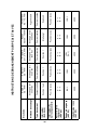
CONNECTION INSTRUCTIONS FOR PEG1 AND A6 VEC
Electrode
Single wire
2,5 - 6mm
Single wire
2,5 - 6mm
Twin wire
2x1,2 - 3,0mm
Strip.br.
0,5x30 - 100mm
Carbon electrode
8,0 - 12,7mm
Weldin g method
Submerged arc
welding
Submerged arc
welding
Submerged arc
welding
Submerged arc
welding
Arc air gouging
Current type Direct Alternating Direct Direct Direct
Switch
(feed-back)
Position1or2 Position 1 Position 1 Läge 1 Position 2
Switch (9),
Sequence card
Up position Up position Down position Up position Up position
Regulator card
connectio n
(A6 VEC)
X--1
B--7
X--1
B--7
X--1
B--7
X--1
B--7
X--1
B--7
Ratio
(A6 VEC)
156:1 156:1
156:1
(74:1)
156:1 156:1
Motor rotor r/min
(A6 VEC)
4000 4000 4000 4000 4000

-- 1 3 --
mmvarnga
WARNUNG
BEIM LICHTBOGENSCHWEIßEN UND LICHTBOGENSCHNEIDEN KANN IHNEN
UND ANDEREN SCHADEN ZUGEFÜGT WERDEN. DESHALB MÜSSEN SIE BEI
DIESEN ARBEITEN BESONDERS VORSICHTIG SEIN. BEFOLGEN SIE DIE
SICHERHEITSVORSCHRIFTEN IHRES ARBEITGEBERS, DIE SICH AUF DEN
WARNUNGSTEXT DES HERSTELLERS BEZIEHEN.
ELEKTRISCHER SCHLAG -- Kann den Tod bringen.
S Die Schweißausrüstung gemäß örtlichen Standards installieren und erden.
S Keine Stromführenden Teile oder Elektroden mit bloßen Händen oder mit nasser
Schutzausrüstung berühren.
S Personen müssen sich selbst von Erde und Werkstück isolieren.
S Der Arbeitsplatz muß sicher sein.
RAUCH UND GAS -- Können Ihre Gesundheit gefährden.
S Das Angesicht ist vom Schweißrauch wegzudrehen.
S Ventilieren Sie und saugen Sie den Rauch aus dem Arbeitsbereich ab.
UV-- UND IR--LICHT -- Können Brandschäden an Augen und Haut verursachen
S Augen und Körper schützen. Geeigneten Schutzhelm mit Filtereinsatz und
Schutzkleider tragen.
S Übriges Personal in der Nähe, ist durch Schutzwände oder Vorhänge zu
schützen.
FEUERGEFAHR
S Schweißfunken können ein F euer entzünden. Daher ist dafür zu sorgen, daß
sich am Schweißarbeitsplatz keine brennbaren Gegenstände befinden.
GERÄUSCHE -- Übermäßige Geräusche können Gehö rschäden verursachen
S Schützen Sie ihre Ohren. Benutzen Sie Kapselgehörschützer oder andere
Gehörschützer.
S Warnen Sie Umstehende vor der Gefahr.
BEI STÖRUNGEN
S Nur Fachleute mit der Behebung von Störungen beauftragen.
LESEN SIE DIE BETRIEBSANWEISUNG VOR DER
INSTALLATION UND INBETRIEBNAHME DURCH.
SCHÜTZEN SIE SICH SELBST UND ANDERE!

SICHERHEIT
-- 1 4 --
df00f1ga
SICHERHEIT
Der Anwender eines ESAB--Schweißautomaten ist verantwortlich für die Sicherheits-
maßnahmen, die für das Personal gelten, das mit der Anlage oder in deren Nähe ar-
beitet.
Der Inhalt dieser Empfehlung kann als eine Ergänzung der normalen Vorschriften für
den Arbeitsplatz betrachtet werden.
Die Bedienung muß nach gegebenen Anleitungen von Personal ausgeführt werden,
das mit den Funktionen des Schweißautomaten gut vertraut ist.
Ein falsches Manöver, verursacht durch einen fehlerhaften Handgriff, oder die fehler-
hafte Auslösung einer Funktionssequenz, kann eine unnormale Situation herbeifüh-
ren, die Personen-- und maschinellen Sachschaden verursachen kann.
1. Personal, das mit dem Schweißautomaten arbeitet, soll gut vertraut sein mit:
S dessen Handhabung
S dem Standort des Notausschalters
S der Funktion
S den geltenden Sicherheitsvorschriften
Um die Bedienung zu erleichtern, ist jeder elektr. Schalter, Druckknopf oder je-
des Potentiometer mit einem Schild versehen, auf dem der Typ der aktivierten
Bewegung oder der Einschaltung bei Betrieb angegeben sind.
2. Der Bediener soll sicherstellen:
S daß sich kein Unbefugter im Arbeitsbereich des Schweißautomaten befindet,
bevor dieser eingeschaltet wird.
S daß keine Person an der falschen Stelle steht, wenn der Wagen oder Schlit-
ten gefahren wird.
3. Der Arbeitsplatz soll:
S frei von Maschinenteilen, Werkzeugen oder anderen Materialen sein, so daß
der Bediener nicht bei der Arbeit im Arbeitsbereich behindert wird.
S mit einem Notausschalter versehen sein, der leicht zugänglich ist.
4. Persönliche Schutzausrüstung
S Immer die vorgeschriebene, persönliche Schutzausrüstung wie z.B. Schutz-
brille, feuersichere Arbeitskleidung, Schutzhandschuhe tragen.
S Sicherstellen, daß keine lose getragenen Gegenstände wie Gürtel, Armbän-
der usw. hängenbleiben.
5. Sonstiges
Stromführende Teile sind normalerweise berührungsgeschützt.
S Kontrollieren, ob der angewiesene Rückleiter gut angeschlossen ist.
S Eingriffe in elektr. Geräten dürfen nu r von einem Elektriker vorgenommen
werden.
S Erforderliche F euerlöschausrüstung muß an einem gut sichtbaren Platz
leicht zugänglich sein.
S Schmierung und Wartung des Schweißautomaten darf nicht während des
Betriebs erfolgen.

TECHNISCHE BESCHREIBUNG
-- 1 5 --
dfa4d1ga
TECHNISCHE BESCHREIBUNG
Der Schweißau to mat A6 TFD1 ist auf einem Traktorwagen montiert und für das
UP --Schweißen von Stumpf -- und Kehlnähten (mit Gleich-- oder Wechselstrom) vor-
gesehen.
Der Schweißau to mat A6 TFD2 mit zwei Schweißköpfen ist auf einem Traktorwagen
montiert und für das UP --Schweißen von Stumpfnähten vorgesehen (mit Gleich--
oder Wechselstrom).
Der Schweißau to mat A6 TGD1 ist auf einem Traktorwagen montiert und für das
MIG/MAG--Schweißen von Stumpf-- und Kehlnähten vorgesehen (mit Gleichstrom).
Der Schweißkopf kann horizontal und vertikal mit den Linealschlitten eingestellt wer-
den. Die Winkelbewegung wird mit dem Winkelschlitten eingestellt.
Alle übrige Verwendung ist verboten.
TECHNISCHE DATEN
A6 TFD1 A6 TFD2 A6 TGD1
Zulässige Belastung 1500 A DC/AC 1500 A DC/AC 600 A DC
Elektrodendimension
Volldraht einfache Drahtelektrode 3,0--6,0 mm 3,0--6,0 mm 1,0--2,4 mm
Fülldraht 1,6--3,2 mm
doppelte Drahtelektrode 2x2,0--2x3,0
Max. Elektrodengeschwindigkeit 4,2 m/min 4,2 m/min 17,5 m/min
Max. Betriebsgeschwindigkeit 2,5 m/min 2,5 m/min 2,5 m/min
Max. Elektrodengewicht 30 kg 30 kg 30 kg
Inhalt des Pulverbehälters
(Darf nicht mit vorgewärmtem Pulver ge-
füllt werden)
10 l 10 l
Gewicht (exkl. Elektrode und Pulver) 110 kg 158 kg 100 kg
Bremsmoment der Bremsnabe 1,5 Nm 1,5 Nm 1,5 Nm
Max. Neigung in seitlicher Richtung 25_ 25_ 25_
Anschlußspannung 42 V AC 42 V AC 42 V AC
Kontinuierlich A--gemessener Schalldruck 68 dB 68 dB 83 dB
Siehe Maßbild auf Seite 49 und auf Seite 50.

aza5dp17
INSTALLATION
-- 1 6 --
dfa4i1ga
INSTALLATION
Anschluß Schweißautomat -- Schweißstromquelle
1. Den Schweißautomaten für das Stumpf-- und Kehlnahtschweißen einstellen, sie -
he Abb. auf Seite 49.
2. Drahtvorschubmotor A6 VEC siehe Bedienanleitung 443 393.
3. Bedieneinheit PEG1, siehe Bedieneinheit 443 392.
4. Kabel gemäß Schaltplan auf Seite 51 und Seite 52 anschließen.
S Gleichstrom
S Steuerkabel (08) für A6 TF D1 bzw. (15) für A6 TGD1 zwischen Schweiß-
stromquelle (01) und Bedieneinheit PEG1 (02) anschließen.
S Mit Kabelschuh versehene Leitung (07) bzw. (08) zwischen Schweiß-
stromquelle (01) und Shunt anschließen.
S Wechselstrom
S Steuerkabel (08) zwischen Zusatzeinheit (11) und Bedieneinheit PEG1
(02) anschließen
S Zusatzeinheit (11) an der Schweißstromquelle (10) anschließen.
S Schweißleitung (07) zwischen Schweißstromquelle (10) und Shunt an-
schließen
S Rückleiter zwischen Schweißstromquelle (01, 10) und Werkstück anschli-
eßen.
S Meßleitung (09) bzw. (16) zwischen Werkstück und Schweißstromquelle
(01,10) oder zwischen Werkstück und Bedieneinheit PEG1 (02) anschließen
(z.B. wenn ein anderes Stromquellenfabrikat verwendet wird).
S Motor mit Getriebe A6 VEC an die Bedieneinheit PEG1 (02) anschließen.
Überprüfen, ob die Bedieneinheit PEG1 gemäß Tabelle angeschlossen ist auf
Seite 24 und die Übersetzung sowie die Ankerdrehzahl gemäß Tabelle gewählt
wurden.
Laden der Schweißelektrode.
Auswechseln der Drahtspule
S Drahttrommel von der Bremsnabe (2)
demontieren und die Stirnseite (3) lö-
sen.
S Drahtspule (1) auf der Drahttrommel
anbringen und die Stirnseite (3) montie-
ren.
S Drahttrommel bzw. Wegwerftrommel auf der
Bremsnabe (2) montieren.
ACHTUNG! Position des Mitnehmers.

INSTALLATION
-- 1 7 --
dfa4i1ga
WICHTIG!
Um zu verhindern, daß die Drahttrommel
von der Bremsnabe rutscht:
Lås ist die Drahttrommel mit dem roten
Drehgriff gemäß Warnaufkleber an der
Bremsnabe zu verriegeln
(siehe nebenstehende Abb.)
5. Kontaktausrüstung
S Einfachdraht 1,6 -- 2,5 mm (4,0 mm). Light duty (D20)
Wird bei Bedarf z.B. in engen Räumen verwendet, Drahtdurchmesser bis zu
4,0 mm.
Kontaktrohr D20 mit Kontaktdüse (M12--Gewinde) verwenden, siehe Tabelle
auf Seite 55.
S Düse mit dem Schlüssel Nr. 10 festziehen, um einen guten Kontakt zu
gewährleisten.
Für kleinere Drahtelektroden mit einem Durchmesser von 1,6 -- 2,5 mm,
Führungsrohr und separates Kleindrahtrichtwerk verwenden.
S Die Klemme für das Führungsrohr im M12--Loch für die feste Richtrolle
des Standard --Drahtrichtwerks montieren. Das Führungsrohr soll an der
Kontaktdüse anliegen. Evtl. ist die Länge zu verkürzen, so daß der Ab -
stand zur Vorschubrolle etwa 5 mm beträgt
S Das Kleindrahtrichtwerk auf der Oberseite der Klemme für das Drah-
trichtwerk montieren.
S Einfachdraht 3,0 -- 6,0 mm. Heavy duty (D35)
Kontaktrohr D35 mit Kontaktbacken verwenden. Siehe auch Anmerkung hin-
sichtlich des Kontaktrohrs D20 für Drahtdurchmesser bis zu 4,0 mm in en-
gen Räumen.
S Standarddrahtrichtwerk für A6 verwenden, wobei das Richtwerk aus ei -
ner festen und einer losen Richtrolle besteht.
S Die Kontaktbacken mit den mitgelieferten M5--Schrauben montieren, ein
Teil der Kontaktbacke im festen Kontaktrohr und ein Teil in der losen
Hälfte des geteilten Kontaktrohrs.
S Die lose Hälfte mit Kontaktbacke an ihren Platz unter der Druckschraube
montieren und festziehen, so daß zwischen Kontaktbacke und Draht-
elektrode ein guter Kontakt erhalten wird.
S Fülldrähte
Für Fülldrähte können die Kontaktrohre D20 und D35 verwendet werden.
Wenn Kontaktrohre (D35) verwendet werden, darf der Druck beim Festzie-
hen der Kontaktbacken nicht zu groß sein, damit der Fülldraht nicht defor-
miert wird. Dafür sorgen, daß ein guter Kontaktübergang zum Draht erhalten
wird.

INSTALLATION
-- 1 8 --
dfa4i1ga
S Doppeldraht
Für Doppeldraht mit Führungsrohr und separatem Drahtrichtwerk immer das
Kontaktrohr D35 verwenden.
S Klemme für das Führungsrohr im M12--Loch für die feste Richtrolle des
Standarddrahtrichtwerks montieren. Das Führungsrohr soll an der Kon-
taktbacke (Heavy Twin) oder am Adapter für die Kontaktdüse (Light
Twin) anliegen.
S Die Länge des Führungsrohres so anpassen, daß der Abstand zur Vor -
schubrolle etwa 5 mm beträgt.
Doppeldraht 2x1,2 -- 2x2,0 mm, Light Twin:
2 Kontaktdüsen mit M6--Gewinde verwenden. Durchmesser für den jewiligen
Draht, siehe Tabelle auf Seite 55.
S Kontaktdüsen gut festziehen, um einen guten Kontakt zu erhalten.
S Adapter für die M6--Kontaktdüsen mit einer M5--Schraube im festen Teil
des geteilten Kontaktrohrs montieren. Druckschraube und die lose Hälfte
des Kontaktrohrs ist bei dieser Anwendung nicht erforderlich.
Doppeldraht 2x2,0 -- 2x3,0 mm, Heavy Twin:
S Für dicke Drahtelektroden Kontaktbacke Twin verwenden
(2x2,0 mm, siehe auch Light Twin).
S Kontaktbacke mit den mitgelieferten M5--Schrauben montieren.
ACHTUNG! Kontaktbackenhälfte mit Nase im festen Teil des Kontak-
trohrs montieren.
S Die lose Hälfte des Kontaktrohrs beim Laden von neuen
S Drahtelektroden demontieren, indem die Druckschraube gelöst wird.
S Die Drahtelektrode vorschieben und in die Führung der festen Kontakt-
backenhälfte (Nase) einführen.
S M5--Schraube der Kontaktbacke lösen und die lose Hälfte mit der In-
busschraube M8 montieren, so daß die Kontaktbackenhälfte mit Nase
und die gegenwirkende Kontaktbackenhälfte die Drahtelektroden umsch-
ließen. Der lose Teil des Kontaktrohrs wird mit M5--Schrauben festgezo-
gen, so daß ein guter Kontakt erhalten wird.
S Einstellung der Drahtelektroden beim Twinarc--Schweißen:
Die Drahtelektroden in den Nähten werden auf ein optimales Schweißergeb-
nis eingestellt, indem das Kontaktrohr gedreht wird. Die beiden Drahtelektro-
den können so gedreht werden, daß sie sich nacheinander in einer Linie mit
der Naht oder in einer wahlfreien Position bis zu 90&gr quer über der Naht
befinden, d.h. eine Drahtelektrode auf jeder Seite der Naht.
S Tandemschweißen
S Der Abstand zwischen der ersten und zweiten Drahtelektrode darf nicht
so groß sein, daß die Schlacke hart werden kann, bevor die zweite
Drahtelektrode kommt.
S Dafür sorgen, daß zwischen der ersten und zweiten Drahtelektrode aus-
reichend Pulver vorhanden ist.
Seite wird geladen ...
Seite wird geladen ...
Seite wird geladen ...
Seite wird geladen ...
Seite wird geladen ...
Seite wird geladen ...
Seite wird geladen ...
Seite wird geladen ...
Seite wird geladen ...
Seite wird geladen ...
Seite wird geladen ...
Seite wird geladen ...
Seite wird geladen ...
Seite wird geladen ...
Seite wird geladen ...
Seite wird geladen ...
Seite wird geladen ...
Seite wird geladen ...
Seite wird geladen ...
Seite wird geladen ...
Seite wird geladen ...
Seite wird geladen ...
Seite wird geladen ...
Seite wird geladen ...
Seite wird geladen ...
Seite wird geladen ...
Seite wird geladen ...
Seite wird geladen ...
Seite wird geladen ...
Seite wird geladen ...
Seite wird geladen ...
Seite wird geladen ...
Seite wird geladen ...
Seite wird geladen ...
Seite wird geladen ...
Seite wird geladen ...
Seite wird geladen ...
Seite wird geladen ...
Seite wird geladen ...
Seite wird geladen ...
Seite wird geladen ...
Seite wird geladen ...
-
 1
1
-
 2
2
-
 3
3
-
 4
4
-
 5
5
-
 6
6
-
 7
7
-
 8
8
-
 9
9
-
 10
10
-
 11
11
-
 12
12
-
 13
13
-
 14
14
-
 15
15
-
 16
16
-
 17
17
-
 18
18
-
 19
19
-
 20
20
-
 21
21
-
 22
22
-
 23
23
-
 24
24
-
 25
25
-
 26
26
-
 27
27
-
 28
28
-
 29
29
-
 30
30
-
 31
31
-
 32
32
-
 33
33
-
 34
34
-
 35
35
-
 36
36
-
 37
37
-
 38
38
-
 39
39
-
 40
40
-
 41
41
-
 42
42
-
 43
43
-
 44
44
-
 45
45
-
 46
46
-
 47
47
-
 48
48
-
 49
49
-
 50
50
-
 51
51
-
 52
52
-
 53
53
-
 54
54
-
 55
55
-
 56
56
-
 57
57
-
 58
58
-
 59
59
-
 60
60
-
 61
61
-
 62
62


ESAB A6 TFD1 / TFD2 / TGD1 Benutzerhandbuch
- Kategorie
- Spielzeuge
- Typ
- Benutzerhandbuch
in anderen Sprachen
- English: ESAB A6 TFD1 / TFD2 / TGD1 User manual
- français: ESAB A6 TFD1 / TFD2 / TGD1 Manuel utilisateur
- Nederlands: ESAB A6 TFD1 / TFD2 / TGD1 Handleiding
Verwandte Artikel
-
ESAB A6 SFF1C Compact 500 Benutzerhandbuch
-
-
ESAB A6 SFD2 Benutzerhandbuch
-
-
-
ESAB A2 Automatic welding machines with Welding Control Unit PEI Benutzerhandbuch
-
ESAB A6 Mastertrac Benutzerhandbuch
-
-
-