
Gebrauchsanleitung
Instruction Manual
Art. No. 49-26000
GB
D
Aluminium-Bodenstativ
Aluminium Tripod

- 2 -
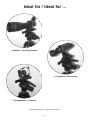
... Spektive / Spotting Scopes.
Ideal für / Ideal for ...
... Ferngläser / Binoculars.
... Fotoapparate / Cameras.
Anwendungsbeispiele / Suggested application

- 3 -
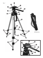
Fig. 1
Fig. 2
Nylontasche

Alle Teile (Fig. 1):
Schraubgewinde (Stativkopfplatte)
Stativkopfplatte
Feststellhebel (Stativkopf)
Feststellschraube
Feststellschraube
Führungsgriff
Feststellschraube
Kurbel (ausklappbar)
Schnellspannring
Libelle
Tragegriff
Utensilienhaken
Feststellclips (6)
Stativbeine (3)
Spinne
Wasserwaage
Feststellschraube
Details (Fig. 2):
Schraubgewinde (Stativkopfplatte)
Stativkopfplatte
Feststellhebel (Stativkopf)
Feststellschraube
Feststellschraube
Führungsgriff
Feststellschraube
Kurbel (ausklappbar)
D
- 4 -
1. Allgemeines
Dieses standfeste, höhenverstellbare Bodenstativ ist für alle Spektive oder Ferngläser
mit genormtem Stativanschlussgewinde geeignet. Es verfügt über zahlreiche nützliche
Funktionen wie z.B. Höhenverstellung, Handführung oder einen neigbaren Stativkopf.
Wählen Sie als Standort für Ihr Aluminiumstativ stets einen ebenen und festen
Untergrund. Für optimale Beobachtungen ist die richtige Standortwahl äußerst wichtig.
2. Aufstellen des Stativs
Öffnen Sie die Feststellclips (13) an den Stativbeinen (14) und ziehen Sie diese so weit
wie möglich heraus. Schließen Sie danach die Clips wieder.
Halten Sie nun den Tragegriff (11) fest und lösen Sie den Schnellspannring (9) durch eine
kurze Rechtsdrehung. Schieben Sie den Schnellspannring nach unten, so dass sich die
Stativbeine im Bereich der Spinne (15) auseinander bewegen. Ziehen Sie anschließend
den Schnellspannring wieder handfest an.
Hinweis: Achten Sie darauf, dass sich der blaue Kreis der Libelle (10)
mittig im roten Kreis befindet. Nur so ist gewährleistet, dass
das Stativ absolut waagrecht ausgerichtet ist. Korrigieren Sie
gegebenenfalls die Position durch Heraus- oder
Hineinschieben einzelner Stativbeine!
1

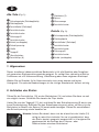
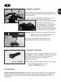
3. Spektiv aufsetzen
Drücken Sie den Feststellhebel (3) am Sativkopf zur
Seite und entnehmen Sie die Stativkopfplatte (2) der
Halterung (Fig. A).
An der Unterseite ihres Spektivs befindet sich das
Stativanschlussgewinde.
Befestigen Sie die Stativkopfplatte
(2) am Stativ, indem Sie das
Schraubgewinde (1) in das Stativ-
anschlussgewinde am Spektiv
eindrehen. Dazu müssen Sie an
der Unterseite der Stativkopfplatte
die Metallöse (Fig. B) aufstellen.
Hinweis: Achten Sie darauf, dass das Objektiv des
Spektivs wie in Fig. C dargestellt an der
Stativkopfplatte ausgerichtet wird.
Setzen Sie anschließend das Spektiv samt
Stativkopfplatte wieder in die Halterung ein.
4. Fernglas aufsetzen
Das Anbringen eines Fernglases erfolgt ebenso wie
beim Spektiv. Jedoch benötigen Sie hierfür zusätzlich
einen Stativadapter (Fig. D), der zuvor auf das
Stativanschlussgewinde des Fernglases
aufgeschraubt wird.
Info: Den Bresser Stativadapter können Sie in Ihrem
Foto-/Optikfachhandel unter der
Art. No. 19-16500 bestellen.
5. Funktionen
Höhenverstellung mit der Kurbel:
Lösen Sie die Feststellschraube (7) und klappen Sie
die Kurbel (8) aus. Nun können Sie das Stativ bequem durch Drehen der Kurbel in der
Höhe verstellen. Ziehen Sie nach jeder Verstellung die Feststellschraube (7) wieder
handfest an.
- 5 -
D
3
2
Fig. A
Fig. B
1
Fig. C
Objektiv
Fig. D
Art. No. 19-16500
D

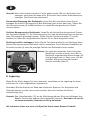
Vorsicht: Wenn die Feststellschraube (7) nicht gelöst wurde, läßt sich die Kurbel nicht
bewegen. Versuchen Sie dann nicht, die Kurbel unter hohem Kraftaufwand zu
bewegen. Die Kurbel kann abbrechen!
Horizontale Bewegung des Stativkopfs: Lösen Sie die Feststellschraube (5) und
bewegen Sie mittels Führungsgriff (6) den Stativkopf nach rechts oder links. Ziehen Sie
die Feststellschraube (5) wieder handfest an, sobald Sie das gewünschte Objekt
anvisiert haben.
Vertikale Bewegung des Stativkopfs: Lösen Sie die Vertikal-Arretierung durch Drehen
der Feststellschraube (17). Die Feststellung löst sich und der Stativkopf kann vertikal mit
dem Führungsgriff (6) bewegt werden. Ziehen Sie die Feststellschraube (17) wieder
handfest an, wenn Sie die gewünschte Position für Ihr Gerät eingestellt haben.
Stativkopf seitlich umklappen: Wenn Sie die Feststellschraube (4) am Stativkopf lösen,
können Sie den gesamten Stativkopf seitlich umklappen. Durch Anziehen (handfest) der
Feststellschraube (4) kann die jeweilige Position des Stativkopfs fixiert werden.
Hinweis: Die optimale horizontale Ausrichtung des
Stativkopfs ist dann erreicht, wenn die im
Stativkopf eingearbeitete Wasserwaage (16)
richtig ausgerichtet ist. Dazu muss sich die
Luftblase mittig zwischen den beiden
Strichen befinden (Abb. E).
6. Lagerung
Wenn Sie Ihr Stativ längere Zeit nicht benutzen, empfehlen wir die Lagerung an einem
trockenen Ort in der mitgelieferten Nylontasche.
Vermeiden Sie den Kontakt mit Sand oder ähnlichem Schmutz. Die Scharniere und
Gewinde können so stark verschmutzt werden, dass die Funktion des Stativs
beeinträchtigt wird.
Hinweis: Den Utensilienhaken (12) an der Mittelstange können Sie zum Aufhängen Ihrer
Spektiv-Tasche oder anderer Utensilienbeutel benutzen. Der Haken ist nur bis
zu einem maximalen Gewicht von 800 g belastbar!
Wir wünschen Ihnen nun noch viel Spaß mit Ihrem neuen Bresser-Produkt!
- 6 -
1
Fig. E
D

- 7 -
Garantie
Die Garantiezeit beträgt 2 Jahre und beginnt am Tag des Kaufs.
Im Falle einer Garantieleistung setzen Sie sich bitte mit dem Händler, bei dem Sie dieses
Produkt gekauft haben, in Verbindung. Er wird sich um eine zügige Abwicklung
bemühen.
Bitte den Kassenbon (oder Kopie) beilegen.
Name:....................................................................................................................................
PLZ/Ort: ................................................................................................................................
Straße: ..................................................................................................................................
Telefon:..................................................................................................................................
Unterschrift: ..........................................................................................................................
Kaufdatum: ................................................
Modell:........................................................ Geräte-Nr.: ......................................................
Diese Garantie zusammen mit dem Kassenbeleg aufbewahren.
..............................................................................................................................................
Kaufdatum/Stempel/Unterschrift des Händlers
D
Technische Daten
Nettogewicht:................................ 1,75 kg
Max. Arbeitshöhe: ........................ 161 cm
Belastbarkeit: .................................. 3,5 kg
D

1. Overview
This solid Bresser Field Tripod can be used for all Bresser Binoculars and
Spottingscopes as well as for all instruments with a standard Tripod thread. Practical
features include: its easy to use pan handle, height adjustment and its tilting head.
A suitable positioning location for your tripod should always be a level and solid ground.
The location is vital for an optimal observation.
2. Tripod Assembly
Open the quick release clips (13) on the tripod legs (14) and pull the legs out as far as
they can go. Re-tighten the clips.
Hold the handle (11) and release the adjustable tension ring (9) by turning it clockwise.
Push the adjustable tension ring down until the braces (15) have pushed out the legs all
the way.
Notice: Make sure that the blue circle within the level (10) is located in
the middle of the red circle. Only then is the tripod level! Adjustments
can be made by sliding individual tripod legs in or out.
- 8 -
1
Components (Fig. 1):
Mount screw
Mount plate
Quick release (Mount plate)
Locking screw (90˚ Vertical platform)
Locking screw (Tilting head)
Panhandle
Locking screw (Telescopic arm)
Crank
Adjustable tension ring
Level
Handle
Hook
Quick release clips (6)
Tripod legs (3)
Braces
Level
Locking screw (Horizontal)
Detailed View (Fig. 2):
Mount screw
Mount plate
Quick release (Mount plate)
Locking screw (90˚ Vertical platform)
Locking screw (Tilting head)
Panhandle
Locking screw (Telescopic arm)
Crank
GB

G
B
- 9 -
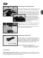
3. Mounting a Spotting Scope
Pull the quick release lever (3) on the tripod mount and
remove the mount plate (2) from its socket (Fig. A.).
The tripod thread of your spotting scope is located
on the bottom side of the scope. Screw the mount
plate (2) onto the spotting scope
by inserting the mount screw (1)
into the tripod thread of your
spotting scope and tightening it.
The metal lug on the underside of
the mounting plate must be
erected so that the screw can be
turned (Fig.A)!
Notice: Make sure that the spotting scope objective
is aligned properly with the mounting plate (Fig. C).
After that, place the spotting scope with the mount
plate into the mount plate socket.
4. Mounting a Binocular
The mounting of a binocular onto the Bresser tripod
uses the same steps as indicated in the spotting scope
assembly instructions. However, a tripod adapter is
additionaly needed (Fig. D). The tripod adapter should
be screwed onto your binoculars mount screw.
Please note: The Bresser Tripod Adapter
(Art. No. 19-16500) can be purchased
at your local Photo/Optical dealer.
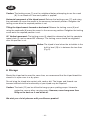
5. Functions
Height adjustment with the crank: release the locking screw (7) and fold out the crank
(8). The tripod’s telescopic arm can now be cranked up or down. The locking screw (7)
should be retightend after the height adjustment!
3
2
Fig. A
Fig. B
1
Fig. C
Objective
Fig. D
Art. No. 19-16500
GB

Caution: The locking screw (7) must be untightend before attempting to use the crank
(8). It can break off if too much power is applied!
Horizontal movement of the tripod mount: Release the locking screw (17) and using
the panhandle (6) move the mount in the necessary horizontal position. Retighten the
locking screw once the required position is set.
Tilting the tripod mount forward or backward: Release the locking screw (5) and
using the panhandle (6) move the mount in the necessary position. Retighten the locking
screw once the required position is set.
90˚ Vertical movement: The locking screw (4) should be released so that the complete
mount plate (2) can be moved 90° sideways. The locking screw should be retightend
after the position is set.
Notice: The tripod is level when the air bubble in the
built-in level (16) is in between the two lines
(Fig. E).
6. Storage
Should the tripod not be used for some time, we recommend that the tripod should be
stored in its nylon case in a dry place.
Do not bring the tripod into contact with sand or dirt. The hinges and threads can
become blocked and the functionality of your tripod may be impaired.
Caution: The hook (12) can be utilized to hang up your spotting scope / binocular
protective case or other carrying cases. However, never hang more than
800g on the hook as it can break off.
We wish you a lot of pleasure with your Bresser product!
- 10 -
1
Fig. E
GB

- 11 -
G
B
Warranty
The period of warranty is 2 years, beginning on the day of purchase.
Please contact the dealer you purchased this product from, for any warranty issues.
Please also enclose the cash receipt (or a copy).
Name: ..................................................................................................................................
Postal Code/City: ................................................................................................................
Street: ..................................................................................................................................
Telephone: ............................................................................................................................
Signature: ............................................................................................................................
Purchase date: ..........................................
Model: ...................................................... Item No.: ........................................................
Please keep this guarantee along with your receipt.
..............................................................................................................................................
Purchase date / Stamp / Signature of dealer
Technical Data
Net weight:.................................... 1,75 kg
Max. height: .................................. 161 cm
Max. load bearing capacity:............ 3,5 kg
GB

Bresser GmbH
Gutenbergstr. 2 · DE-46414 Rhede
Tel. +49 (0) 28 72 - 80 74-210
Fax +49 (0) 28 72 - 80 74-222
www.bresser.de · service@bresser.de
ANL4926000DEGB0807BRESSER
Irrtümer und technische Änderungen vorbehalten. · Errors and technical changes reserved.
-
 1
1
-
 2
2
-
 3
3
-
 4
4
-
 5
5
-
 6
6
-
 7
7
-
 8
8
-
 9
9
-
 10
10
-
 11
11
-
 12
12


Bresser 4926000 Bedienungsanleitung
- Typ
- Bedienungsanleitung
- Dieses Handbuch eignet sich auch für
in anderen Sprachen
- English: Bresser 4926000 Owner's manual
