
1
Stand 08.2018 (18 / 002.2) 4 12 696 04
RFHSB - 060.010
RFHSB - 060.011
RFHSB - 060.010
RFHSB - 060.011
– Raumhygrostat Befeuchten / Entfeuchten mit Sollwerteinstellung außen
– Room hygrostat for humidifying / dehumidifying with external set value setting
– Hygrostat d’ambiance type humidification / déshumidification avec ajustage de la valeur de consigne externe
– Raumhygrostat Befeuchten / Entfeuchten mit Sollwerteinstellung innen
– Room hygrostat for humidifying / dehumidifying with internal set value setting
– Hygrostat d’ambiance type humidification / déshumidification avec ajustage de la valeur de consigne interne
Sicherheitshinweis!
Dieses Gerät darf nur durch eine Elektrofachkraft geönet und gemäß dem entsprechenden
Schaltbild im Gehäusedeckel / auf dem Gehäuse / in der Bedienungsanleitung installiert wer-
den. Dabei sind die bestehenden Sicherheitsvorschriften zu beachten. Nach der Installation
ist der Betreiber, durch die ausführende Installationsfirma, in die Funktion und Bedienung der
Regelung einzuweisen. Die Bedienungsanleitung muss für Bedien- und Wartungspersonal an
frei zugänglicher Stelle aufbewahrt werden.
Safety information!
No persons other than expert electricians only must open this device in due compliance with
the wiring diagram shown in the housing cover / on the housing / represented in the correspond-
ing operating instructions. All expert electricians committed to the execution of any such works
must comply with the relevant safety regulations currently operative and in force. The company
charged with the installation of the device must, after the completion of the installation works,
instruct the user of the control system into its functions and in how to operate it correctly. These
operating instructions must be kept at a place that can be accessed freely by the operating
and / or servicing personnel in charge.
Entsorgungshinweis
Gerät nicht im Hausmüll entsorgen! Elektronische Geräte sind entsprechend der Richt-
linie über Elektro- und Elektronik - Altgeräte (WEEE - Richtlinie) über die örtlichen Sam-
melstellen für Elektronik - Altgeräte zu entsorgen.
1. Anwendung
Dieser Regler wurde speziell zur Ansteuerung von Be- und Entfeuchtungsgeräten oder ent-
sprechenden Klimaanlagen für Hotel-, Wohn- und Geschäftsräume, und anderen Räumen mit
sauberer, nichtaggressiver Umgebung entwickelt. Für andere, vom Hersteller nicht vorherzu-
sehende Einsatzgebiete, sind die dort gültigen Sicherheitsvorschriften zu beachten. Eignung
hierfür siehe Punkt7. Gewährleistung.
2. Funktion
Die Geräte verfügen über einen Wechselkontakt der mechanisch durch ein hygroskopisches
Kunststoband, das auf die Umgebungsfeuchte reagiert, betätigt wird. Der Wechselkontakt
darf im Schaltspannungsbereich von 24 V ~ bis 250 V ~ betrieben werden. Der RFHSB - 060.010
verfügt über einen von außen zugänglichen Einstellknopf. Der RFHSB - 060.011 ist wegen der
Inneneinstellung des Sollwerts besonders für Behörden, Schulen und ähnlich öentliche Ge-
bäude geeignet. Lange Standzeiten unter 30 % r.H. kann zum Austrocknen des Kunststoban-
des und zu Fehlmessungen nach Rückkehr in den Regelbereich führen. Nach Austrocknung
benötigt der Fühler längere Zeit um sich wieder anzugleichen. Es empfiehlt sich in diesen Fall
den Regler einer höheren Umgebungsfeuchte auszusetzen. Eine Betauung ist in jedem Fall zu
vermeiden.
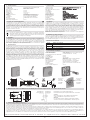
3. Installation
Je nach Gerätetyp oder Verpackungsgröße, wird das Gerät entweder geschlossen oder der
schnelleren Montage wegen geönet ausgeliefert. Der Regler ist zur Montage auf die Wand
oder UP - Dose bestimmt und darf nicht direkt Wärme- oder Kältequellen ausgesetzt werden.
Es ist darauf zu achten, dass der Regler auch rückseitig keiner Fremderwärmung oder - küh-
lung, z.B. bei Hohlwänden durch Zugluft oder Steigleitungen ausgesetzt wird. Vor dem Schlie-
ßen des RFHSB - 060.011 wird der gewünschte Sollwert eingestellt. Hierzu befindet sich im
Gehäusedeckel eine gesonderte Anweisungsskizze. Das Önen und Schließen erfolgt wie in
den Zeichnungen dargestellt.
Achtung! Bei Verwendung von Spannungen außerhalb des Kleinspannungsbereiches, darf das
Gerät nicht auf leitfähigem Untergrund installiert werden.
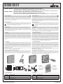
3.1 Bereichseinengung des Einstellbereichs
Mittels der Einstellfahnen unter dem Einstellknopf kann der Einstellbereich des RFHSB - 060.010
mechanisch begrenzt werden. Hierzu muss der Knopf abgezogen und nach verstellen der An-
schläge (rot für maximale Feuchte, blau für minimale Feuchte) wieder aufgesteckt werden.
Disposal information
Do not dispose of this device through domestic waste! Electronic devices must be
disposed of in accordance with the Directive on Waste Electrical and Electronic Equip-
ment (WEEE directive) via the local collection points for waste electrical and electronic
equipment.
1. Application
This controller has been specially devised for the control and supervision of humidifiers and
dehumidifiers or corresponding air conditioning systems that are used in clean, nonaggressive
ambiances, such as in living spaces, hotel - and oce - as well as in other rooms. Regarding
other applications not to be foreseen by the manufacturer of this device, the safety standards
these applications need to be followed and adhered to. Regarding the aptitude of the device
for any such application, please refer to section7. herein (Warranty).
2. Functional description
The devices dispose of a changeover contact. The actuation of the contact is eected me-
chanically, meaning through the operation of a hygroscopic plastic ribbon that reacts to the
level of humidity in the ambient air. The changeover contact is admitted for operation within
a switching voltage range from 24 V ~ up to 250 V ~. The RFHSB - 060.010 has been equipped
with an externally accessible adjusting knob. The RFHSB - 060.011 in contrast, is, owing to the
fact that the set value has to be adjusted internally with this model, particularly suited for the
use in oce buildings, schools and other public buildings of similar nature. Longer idle times in
ambiances within which the relative humidity has fallen to below 30 % may lead to the dehydra-
tion of the plastic ribbon and, consequently, to incorrect measuring results after its return to the
control range covered by the device. Once a dehydration of the sensing element occurs, it will
take a longer period of time until the element is again able to converge itself to its former state.
It was, in any such case, recommendable to expose the device to a higher ambient humidity
level. The condensation of moisture must be avoided in any event.
3. Mounting / Installation
The device is, depending on the type version of the device or size of the package used for it,
either delivered in closed or, in order to facilitate its fast installation, also in opened condition.
The controller is determined for installation on an UP box and must not be exposed to any heat
or cold sources whatsoever. Also care must be taken to ensure that it is not exposed to the
influence of heat or cold sources that warm or cool the device at its back (through air flows in
cavity walls or the temperatures radiated by ascending pipelines, f. ex.). The desired set value
needs to be adjusted prior to closing the RFHSB - 060.011. The way in which to do this can be
learned from the separate instruction scheme shown in the housing cover. The opening and
closing of the device takes place as delineated in the related drawings.
Caution: The device must not be installed on a conducting surface when applying any voltages
outside of the low voltage range!
3.1 Delimitation of the setting range
The setting pins located underneath of the adjusting knob enable to delimit the setting range
of the RFHSB - 060.010 mechanically. To enable this, the adjusting knob must be removed by
pulling it o and, after the adjustment of the related pins (red for max. humidity and blue for min.
humidity setting) be put on again in order to lock the limitations.
Klemme Anschlussleitung
1 L, Eingang Schaltspannung
2 Ausgang Befeuchten
3 Ausgang Entfeuchten
Terminal Connecting cable
1 L, switching voltage input
2 output „humidifying“
3 output „dehumidifying“
4. Anschlussklemmen 4. Terminals
Einstellfahne
für minimalen
Feuchtewert
Pin for the setting
of the minimum
humidity value
Einstellfahne
für maximalen
Feuchtewert
Pin for the setting
of the maximum
humidity value

2
ALRE - IT Regeltechnik GmbH
•
Richard - Tauber - Damm 10
•
D - 12277 Berlin
•
Tel.: + 49 (0) 30 / 399 84 - 0
•
Fax: + 49 (0) 30 / 391 70 05
•
•
www.alre.de
5. Technische Daten
Schaltkontakt: potentialfreier Wechselkontakt, Typ 1.B
Schaltspannung: 24 V ~ … 250 V ~, bei 24 V ~
Mindeststrom 100 mA
Max. zulässiger Schaltstrom:
Befeuchten: 2 (0,2) A
Entfeuchten: 5 (0,2) A
Regelbereich: 35 … 85 % r.H.
Schaltdierenz: ca. 7 % r.H.
Fühler: hygroskopisches Kunststoband
Elektrischer Anschluss: Schraubklemmen 0,5 mm
2
… 2,5 mm
2
Schutzart: IP 30 nach entsprechender Montage
Schutzklasse: II nach entsprechender Montage
Montage: auf Wand oder UP - Dose Ø 55 mm
Verschmutzungsgrad: 2
Bemessungsstoßspannung: 4000 V
3. Installation
Le dispositif est, selon son type ou la taille du paquet utilisé pour son emballage, livré soit en
condition fermée ou, pour faciliter son installation rapide, en condition ouverte. Le dispositif
est prévu pour l’installation murale ou sur une boîte encastrée et ne doit pas être exposé à l’in-
fluence de sources de chaleur ou de froid. Il faut également veiller à ce que le dispositif ne soit
pas exposé à l’influence de sources de chaleur ou de froide, qui le chauent ou refroidissent à
sa face arrière (par des courants d’air dans des murs creux ou par les températures répandues
par des conduites montantes, par ex.). La valeur de consigne désirée doit être ajustée avant de
fermer le RFHSB - 060.011. Pour une explication relative à la réalisation de ceci, veuillez vous
reporter au schéma instructif séparé montré dans le couvercle du boîtier. L’ouverture et ferme-
ture du dispositif se font comme démontré dans les dessins correspondants.
Attention! Ne jamais installer le dispositif sur des surfaces conductrices lors de l’application
de tensions hors du domaine basses tensions!
5. Technical data
Switching contact:
Switching voltage:
Max. admissible switching current:
Humidifying:
Dehumidifying:
Control range:
Switching dierence:
Sensing element:
Electrical connection:
Degree of protection:
Protection class:
Installation:
Degree of pollution:
Rated impulse voltage:
potential - free changeover contact, type 1.B
24 V ~ … 250 V ~,
(minimum current 24 V ~ 100 mA)
2 (0.2) A
5 (0.2) A
35… 85 % r.h.
approx. 7 % r.h.
hygroscopic plastic ribbon
terminal screws (0.5 mm
2
… 2.5 mm
2
)
IP 30 (after according installation)
II (after according installation)
on the wall or on an UP box Ø 55 mm
2
4000 V
Consignes de sécurité fondamentale
Uniquement des personnes qualifiées en matière d’électricité doivent ouvrir ce dispositif en
conformité avec le schéma des connexions représenté dans le couvercle du boîtier / apposé
sur le boîtier / représenté dans les notices d’instructions correspondantes. Tous électriciens
spécialisés chargés de l’exécution de tels travaux doivent se conformer aux prescriptions de
sécurité actuellement en vigueur s’y rapportant. La société chargée de l’installation du disposi-
tif doit, après l’achèvement des travaux, initier l’utilisateur aux fonctions du régulateur et à son
opération correcte. Gardez cette notice d’instructions à un lieu librement accessible pour les
opérateurs et hommes de service.
Informations sur l‘élimination
Ne jetez pas l‘appareil dans les ordures ménagères! Les appareils électroniques
doivent être éliminés conformément à la directive relative aux déchets d‘équipements
électriques et électroniques (directive DEEE) via les points de collecte locaux pour les
déchets d‘équipements électriques et électroniques.
1. Application
Ce régulateur a été spécialement conçu pour le contrôle et surveillance d’humidificateurs et
de déshumidificateurs ou des systèmes de climatisation utilisés dans des ambiances nettes
et non - aggressives, telles comme dans des habitations, des salles ou chambres d’hôtel, des
bureaux ou dans d’autres pièces. En ce qui concerne l’aptitude ou l’approbation du dispositif
pour des telles applications, veuillez également faire attention aux informations de garantie
dans chapitre7. (Garantie) dans cette notice d’instructions.
2. Fonctionnement
Les dispositifs sont munis d’un contact de permutation. L’actionnement de ce contact est
eectué mécaniquement, c’est - à - dire par l’opération d’un ruban hygroscopique en matière
plastique qui réagisse au taux d’humidité qui existe dans l’air ambiant. Le contact de permu-
tation est admis pour l’opération dans les limites d’une gamme de tension de commutation
de 24 V ~ jusqu’à 250 V ~. Le type RFHSB - 060.010 est muni d’un bouton de réglage qui peut
être accédé de l’extérieur. Le modèle RFHSB - 060.011, par contre, convient, en raison du
fait qu’avec celui - ci la valeur de consigne est à ajuster à son intérieur, en particulier pour
l’utilisation dans des immeubles de bureaux, des écoles ou dans d’autres immeubles publics
d’une nature similaire. Des temps d’inactivité plus longs dans des ambiances dans lesquelles
l’humidité relative était tombée en dessous d’une valeur de 30 % peuvent aboutir à la déshy-
dratation du ruban plastique et, par conséquent, après le retour du ruban à la plage de réglage
normalement couverte par le dispositif, à des résultats de mesure incorrects. Une fois une
déshydratation du capteur survenue, il prend une période plus longue jusqu’à ce que le capteur
soit encore capable de s’assimiler à son premier état. Il serait, dans un tel cas, recommandable
d’exposer le dispositif à un degré d’humidité ambiante plus haut. La condensation de l’humi-
dité ambiante est à éviter en tout cas.
3.1 Limitation de la plage de réglage
Les broches de réglage existant en dessous du bouton de réglage permettent de limiter méca-
niquement la plage de réglage du régulateur RFHSB - 060.010. Pour faire ça, d’abord enlever le
bouton de réglage et ensuite régler les limites (broche rouge pour l’humidité maximale et bleue
pour l’humidité minimale). Après ceci, encore monter le bouton de réglage.
4. Bornes de raccordement
5. Caractéristiques techniques
Contact d’interruption: contact de permutation sans potentiel, type 1.B
Tension de commutation: 24 V ~ … 250 V ~
(courant minimal à 24 V ~ 100 mA)
Courant d’interruption max. admissible:
Humidification: 2 (0.2) A
Déshumidification: 5 (0.2) A
Plage de réglage: 35 … 85 % HR
Diérentiel: env. 7 % HR
Capteur: ruban hygroscopique en matière plastique
Raccordement électrique: bornes à vis (0,5 mm
2
… 2,5 mm
2
)
Indice de protection: IP 30 (après installation correspondante)
Type de protection: II (après installation correspondante)
Installation: murale ou sur une boîte encastrée Ø 55 mm
Degré de pollution: 2
Tension nominale d‘impulsion: 4000 V
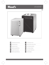
6. Maßbild und Anschluss - Schaltbild / Dimensional drawing and connection diagram / Dessin coté et schéma de branchement
7. Gewährleistung / Warranty / Garantie
Die von uns genannten technischen Daten wurden unter Laborbedingungen nach allgemein gültigen Prüfvorschriften, insbesondere DIN - Vorschriften, ermittelt. Nur insoweit werden Eigen-
schaften zugesichert. Die Prüfung der Eignung für den vom Auftraggeber vorgesehenen Verwendungszweck bzw. den Einsatz unter Gebrauchsbedingungen obliegt dem Auftraggeber; hierfür
übernehmen wir keine Gewährleistung. Änderungen vorbehalten.
The technical data specified herein have been determined under laboratory conditions and in compliance with generally approved test regulations, in particular DIN standards. Technical char-
acteristics can only be warranted to this extent. The testing with regard to the qualification and suitability for the client’s intended application or the use under service conditions shall be the
client’s own duty. We refuse to grant any warranty with regard thereto. Subject to change without notice.
Les données techniques indiquées dans cette notice d’instructions ont été déterminées sous conditions laboratoires en conformité avec des prescriptions d’essai généralement approuvées,
notamment les normes DIN. Les caractéristiques techniques ne peuvent être garanties que dans cette mesure. La vérification du dispositif en rapport à sa qualification et appropriation pour
l’application prévue ou son utilisation sous conditions de service incombe au client. Nous n’assumons aucune garantie à cet égard. Sous réserve de modifications techniques.
Borne Câble de raccordement
1 L, entrée de la tension de commande
2 Sortie „humidification“
3 Sortie „déshumidification“
Entfeuchten
Dehumidifaction
Déshumidification
Befeuchten
Humidifaction
Humidification
Achtung!
Beim Austausch von Geräten ist die geänderte
Klemmenbezeichnung des Ausgangs "Entfeuchten" zu beachten.
Caution!
When replacing devices, the modified terminal designation
of the „Dehumidifaction“ output must be observed.
Attention!
Lors du remplacement des appareils, la désignation modifiée
de la borne de la sortie „Déshumidification“ doit être respectée.
Broche pour
l’ajustage
de la valeur
d’humidité
minimale
Broche pour
l’ajustage
de la valeur
d’humidité
maximale
-
 1
1
-
 2
2


in anderen Sprachen
- English: alre RFHSB-060.010 Quick start guide
- français: alre RFHSB-060.010 Guide de démarrage rapide
Verwandte Artikel
Andere Dokumente
-
Seifert 301410 Bedienungsanleitung
-
Conrad FOX-301A Operating Instructions Manual
-
Fakir LE 46 Bedienungsanleitung
-
DeLonghi DEM8.5 Bedienungsanleitung
-
Zibro S1833 Bedienungsanleitung
-
Maico AKE 150 Mounting And Operating Instructions
-
 Wood’s ED50 Feco Operating Instructions Manual
-
SKYLOTEC LIMESTONE M's Sport Instructions For Use Manual
