
911B.00
Notice d'instructions
Instructions manual
Bedienungsanleitung
Gebruiksaanwijzing
Manual de instrucciónes
Istruzioni d'uso
NU-911B.00/00
■
■
■
■
■
■
Compressiomètre
enregistreur pour
moteur Diésel
Compression
tester for Diesel
engines
Kompressions-
Prüfgerät für
Diesel-Motoren
Compressiemeter
voor Diesel
motoren
Compresometro
para motor Diesel
Compressiometro
per motori Diesel
Seite laden ...

GB D
SPECIFICATIONS 911B.00
Length = 240 mm Width = 90 mm
Weight = 1.1 kg
Scale of diagram = 5 - 60 bar
Graduation = 2.5 bar
Length of hose = 360 mm
Length of starter cord = 1850 mm
Number of curves recorded = 12
(possible cylinders)
Width of curve = 60 mm
Case BV.911B = 430 x 340 x 85mm
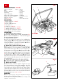
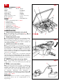
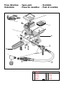
DESCRIPTION
1 - Bevel gear ref : 911B.017
2 - Dummy plugs
3 - Decompression button
4 - Dummy nozzles
5 - Hose ref : 911B.SE2
6 - Starter cord ref : 911B.016
7 - 100 diagram cards ref : 911B.FC
8 - Starter control circuit-breaker
9 - Diagram card feed lever
APPLICATION
1 - Preparing the compressometer
Insert a new diagram card into the recording table fig 2. Push the
table right in. Plug in the starter cord under the handle of the
apparatus.
2 - Preparing the motor
The motor should be warm and the battery in good condition.
Neutralize the fuel intake. Remove all the warm-up nozzles and
plugs. Pull the starter cord
(careful of the joints and washers)
to get rid of
any scale. Plug the starter cord in as in fig 3.
3 - Checking the compression in a cylinder
Fit a dummy nozzle
(or dummy plug)
corresponding to the kind of
nozzle
(or plug)
fitted on cylinder N°1. See table of allocations page
7. Screw the connector of the apparatus onto the dummy nozzle
(or
dummy plug)
. If this is hard to reach, insert the bevel gear between the
hose and the connector. Turn the motor over while pressing the
starter button index 8 located on the handle. Watch the needle ;
when it stabilises at its maximum deviation, stop testing.
Decompress by pushing button index 3 located on the right. The
needle will drop back to zero, and the connector can then be
removed from the dummy nozzle
(or dummy plug)
.
4 - Checking the compression of the other cylinders
After moving the diagram card on a notch using the lever, begin
operation "3" with the other cylinders.
5 - Analysis of the results
During the check, if the needle rises rapidly it signifies that the
rings, valves and cylinder head joint are airtight. The recorded
diagram shows the pressure at the end of compression in each
cylinder checked. The nominal values and their tolerances are
indicated in the manufacturers’ manuals or specialist technical
publications. To locate a leak, use the FACOM leak detector ref.
910A + 910.06.
MAINTENANCE
Keep the apparatus clean, periodically clean the screw threads on
the dummy nozzles and dummy plugs.
KENNDATEN 911B.00
Länge = 240 mm Breite = 90 mm
Gewicht = 1,1 kg
Anzeigebereich = 5 bis 60 bar
Graduierung = 2,5 bar
Schlauchlänge = 360 mm
Startschnurlänge = 1850 mm
Anzahl der aufgezeichneten Kurven = 12
(Zylinder möglich)
Kurvenbreite = 60 mm
Koffer BV.911B = 430 x 340 x 85 mm
BESCHREIBUNG
1 - Winkelumlenkung Art. Nr. 911B.017
2 - Blindkerzen
3 - Dekompressionsknopf
4 - Blindinjektoren
5 - Schlauch Art. Nr. 911B.SE2
6 - Startschnur Art. Nr. 911B.016
7 - 100 Graphikkarten Art. Nr. 911B.FC
8 - Starter-Bedienschalter
9 - Vorschubhebel für Graphikkarte
EINSATZ
1 - Vorbereitung des Drucksetzungsmessers
Eine leere Graphikkarte auf die Aufzeichnungsfläche fig 2 legen.
Die Platte ganz hineinschieben. Die Startschnur unter dem Griff des
Geräts anschließen.
2 - Vorbereitung des Motors
Der Motor muß warm, die Batterie in gutem Zustand sein.
Dieselzufuhr absperren. Alle Injektoren oder Vorheizkerzen
entfernen. Den Starter betätigen
(Vorsicht mit den Dichtungen und
Unterlegscheiben)
, um Zunderpartikel zu eliminieren. Die Startschnur
wie in fig 3 dargestellt anschließen.
3 - Kontrolle der Kompression eines Zylinders
Einen entsprechenden Blindinjektor
(oder eine Blindkerze)
, der dem
Injektormodell
(oder dem der Kerze)
des Zylinders Nr. 1 entspricht,
einsetzen. Siehe Tabelle der Zuweisungen Seite 7. Den Anschluß
des Geräts auf den Blindinjektor schrauben
(oder auf die Blindkerze)
. Ist
die Stelle schwer zugänglich, gibt man die Winkelumlenkung
zwischen Schlauch und Anschluß. Den Motor durch Betätigen des
Starters mit dem Knopf Nr. 8 auf dem Griff drehen lassen. Die
Nadel beobachten : sobald sie auf dem Maximum ihres Ausschlags
stillsteht, den Versuch stoppen. Mit dem Knopf Nr. 3
(rechts)
den
Druck vermindern. Die Nadel fällt auf Null zurück. Jetzt kann man
den Anschluß des Blindinjektors
(oder der Blindkerze)
demontieren.
4 - Kontrolle der Drucksetzung der anderen Zylinder
Nach dem Weiterdrehen der Graphikkarte um ein Maß mit dem
Hebel, beginnt man den Vorgang "3" an den anderen Zylindern.
5 - Analyse der Ergebnisse
Während der Kontrolle, bedeutet ein rasches Ansteigen der Nadel
eine gute Dichtheit auf der Ebene der Segmentierung, der Ventile
und der Zylinderkopfdichtung. Die aufgezeichnete Graphik zeigt
den Druckwert am Ende der Beaufschlagung in jedem geprüften
Zylinder an. Die Nennwerte und ihre Toleranzen sind in den
Hersteller-Handbüchern oder den technischen Herausgaben der
Spezialisten enthalten. Um ein Leck zu orten, benutzt man einen
FACOM-Leck-Detektor Art. Nr. 910A +910.06.
INSTANDHALTUNG
Das Gerät sauber halten, regelmäßig die Gewinde der
Blindinjektoren und Blindkerzen reinigen.
Seite laden ...
Seite laden ...

1
2
4
5
11
7
10
3
12
9
6
8
911B.00
1 911B.012 7 911B.RN1
2 911B.016 8 911B.RN2
3 911B.017 9 911B.SE1
4 911B.0023 10 911B.SE2
5 911B.033 11 911B.SE3
6 911B.FC 100 12 911B.SE5
Pièces détachées - Spare parts - Ersatzteile
Onderdelen - Piezas de recambios - Pezzi di recambio
Seite laden ...
Seite laden ...
-
 1
1
-
 2
2
-
 3
3
-
 4
4
-
 5
5
-
 6
6
-
 7
7
-
 8
8


in anderen Sprachen
- English: Facom 911B.00 Owner's manual
- français: Facom 911B.00 Le manuel du propriétaire
- español: Facom 911B.00 El manual del propietario
- italiano: Facom 911B.00 Manuale del proprietario
- Nederlands: Facom 911B.00 de handleiding
Verwandte Papiere
Sonstige Unterlagen
-
Beta 1480 Bedienungsanleitung
-
Hazet 4794/48 Bedienungsanleitung
-
-
USAG 1315 K1 Benutzerhandbuch
-
Blaupunkt VMW 100 Bedienungsanleitung
-
Innova 3619 Bedienungsanleitung
-
Sony XS-HA1724 Benutzerhandbuch
-
-
-
Italeri Ford Escort Zakspeed Gr. 2 Bedienungsanleitung