Multi-Contact M-0MD-GG Installationsanleitung
- Typ
- Installationsanleitung

EB4 - 23.1013
23.5012 + 23.5013
EB4-A - 23.1014
EB4-A/N - 23.1014
23.5014 + 23.5013
23.5025 + 23.5013
EB4-B - 23.1015
23.5026 + 23.5019
EB4-C - 23.1016
23.5308 + 23.5013
EB4-F - 23.1023
23.5024 + 23.5013
MA103 (de_en)
Montageanleitung
MA103 (de_en)
Assembly instructions
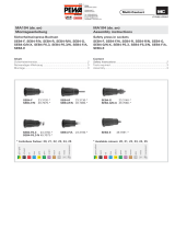
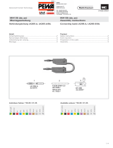
Einpressbuchsen
EB4, EB4-A, EB4-A/N, EB4-B, EB4-C, EB4-F
Press-in sockets
EB4, EB4-A, EB4-A/N, EB4-B, EB4-C, EB4-F
Inhalt
Sicherheitshinweise....................................................................2
Notwendiges Werkzeug ............................................................3
Montage ....................................................................................3
Content
Safety Instructions ....................................................................2
Tools required ............................................................................3
Assembly ................................................................................... 3

Erklärung der Symbole Explanation of the symbols
Warnung vor gefährlicher elektrischer Spannung Warning of dangerous voltages
Warnung vor einer Gefahrenstelle Warning of a hazard area
Nützlicher Hinweis oder Tipp Useful hint or tip
Sicherheitshinweise Safety instructions
Die Montage und Installation der Produkte darf ausschliess-
lich durch qualifi ziertes und erfahrenes Fachpersonal unter
Berücksichtigung aller anwendbaren gesetzlichen Sicher-
heitsbestimmungen und Regelungen erfolgen.
Multi-Contact (MC) lehnt jegliche Haftung infolge Nichteinhal-
tung dieser Warnhinweise ab.
The products may be assembled and installed exclusively by
suitably qualifi ed and trained specialists duly observing all ap-
plicable safety regulations.
Multi-Contact (MC) does not accept any liability in the event of
failure to observe these warnings.
Benutzen Sie nur die von MC angegebenen Einzelteile und
Werkzeuge. Weichen Sie nicht von den hier beschriebenen
Vorgängen zur Vorbereitung und Montage ab, da sonst bei der
Selbstkonfektionierung weder die Sicherheit noch die Einhal-
tung der technischen Daten gewährleistet ist. Ändern Sie das
Produkt nicht in irgend einer Weise ab.
Use only the components and tools specifi ed by MC. In case
of self-assembly, do not deviate from the preparation and as-
sembly instructions as stated herein, otherwise MC cannot
give any guarantee as to safety or conformity with the techni-
cal data. Do not modify the product in any way.
Der Schutz vor einem elektrischen Schlag müssen
bei Installation und Montage/Demontage immer
alle Bauteile spannungsfrei sein.
For protection against electric shock, parts must
be isolated from the power supply while being as-
sembled or disassembled.
Die Steckverbindungen dürfen nicht unter Last
getrennt werden. Das Stecken und Trennen unter
Spannung ist zulässig.
The plug connections must not be disconnected
under load. Plugging and unplugging when live is
permitted.
Vor jedem Gebrauch ist durch Besichtigen (im be-
sonderen die Isolation) zu prüfen, ob keine äusseren
Mängel vorhanden sind. Wenn Zweifel bezüglich der
Sicherheit bestehen, muss ein Fachmann hinzuge-
zogen werden oder der Steckverbinder muss ausge-
tauscht werden.
Each time the connector is used, it should previously
be inspected for external defects (particularly in the
insulation). If there are any doubts as to its safety, a
specialist must be consulted or the connector must
be replaced.
Weitere technische Daten entnehmen Sie bitte dem
Produktkatalog.
For further technical data please see the product
catalogue.

1
2
3
4
Ø 6,8 mm
HSS
Ø 3.9
R1,95
Ø 9
MB4
68
1850
2,1
Ø 4,75
HSS
MB4
+0.1
- 0
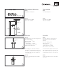
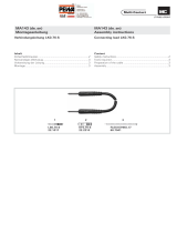
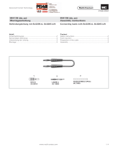
Erforderliches Werkzeug Tools required
(ill.1)
HSS Bohrer Ø 6,8mm
(ill.1)
Drill HSS Ø 6,8mm
(ill. 2)
Montagebolzen MB4,
Bestell-Nr. 25.0032
(ill. 2)
Assembly tool MB4,
Order No. 25.0032
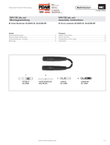
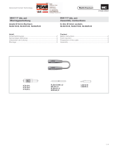
Montage Assembly
(ill. 3)
Fronttafel bohren und einseitig ansen-
ken (ca. 0,5x45°).
Bohrung Ø 6,8 mm
Plattenstärke:
- Metallplatten: 1 - 6mm
- Kunststoffplatten: 3 - 6mm
Max. Buchsen-Ø: 9mm
(ill. 3)
Drill hole and then countersink the
front panel on one side (approx.
0,5x45°).
Drill hole Ø 6,8 mm
Panel thickness:
- metal panels: 1 - 6mm
- plastic panels: 3 - 6mm
Max. diameter socket: 9mm
Als Aufl age der Fronttafel wird vor-
zugsweise ein Kunststoffrohr verwen-
det. Der Durchmesser des Aufl ageroh-
res richtet sich nach den gewählten
Lochabständen.
As an assembly support for the front
panel, a plastic tube can be used. The
tube diameter depends upon the de-
sired distances between the sockets.
(ill. 4)
Isolierteil mit Montagebolzen MB4
einpressen.
(ill. 4)
Press in insulation with the assembly
tool MB4.
+0.1
- 0

Advanced Contact Technology
5
6
MB4
7
© by Multi-Contact AG, Switzerland – MA103 – 11.2012, Index i, Global Communications – Änderungen vorbehalten / Subject to alterations
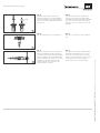
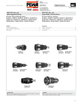
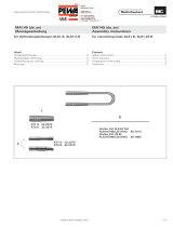
(ill. 5)
Anschluss ausrichten, Buchse in
Isolation vorstecken und mit Monta-
gebolzen MB4 bis zum Anschlag mit
einer Presse oder Tischbohrmaschine
einpressen.
(ill. 5)
Insert socket into the insulation to
the desired connector position (fl at
tab). With the MBe assembly tool and
the help of a press or bench drilling
machine, press in socket to the end
position.
(ill. 6)
Die Einpressbuchse ist einsatzbereit.
(ill. 6)
The press-in socket is now ready for
use.
(ill. 7)
Wenn gewünscht, kann eine Schutz-
kappe zur Abdeckung des Anschlus-
ses montiert werden. Dazu die Schutz-
kappe (KT410-L, Bestell-Nr. 22.2170)
vor dem Anschliessen auf die Leitung
auffädeln und nach erfolgtem An-
schluss über den hinteren Teil der
Einpressbuchse stülpen.
(ill. 7)
If required, the safety hood (KT410-L,
Order No. 22.2170) can be used to
cover up the connection. The hood
must be slipped onto the cable before
making the connection and then
pushed on over the socket body.
-
 1
1
-
 2
2
-
 3
3
-
 4
4


Multi-Contact M-0MD-GG Installationsanleitung
- Typ
- Installationsanleitung
in anderen Sprachen
Verwandte Artikel
-
 Multi-Contact M-0MZ-GG Installationsanleitung
-
 Multi-Contact M-0GP-SW Installationsanleitung
-
 Multi-Contact M-0EH Installationsanleitung
-
 Multi-Contact M-0XV-GG Installationsanleitung
-
 Multi-Contact M-0HC-GG Installationsanleitung
-
 Multi-Contact M-0HF-SW Installationsanleitung
-
 Multi-Contact M-0GC-SW Installationsanleitung
-
 Multi-Contact M-0WA Installationsanleitung
-
 Multi-Contact M-0YQ-GE Installationsanleitung


Andere Dokumente
-
eta Supersonic 2231 90000 Bedienungsanleitung
-
eta Supersonic 1231 90000 Bedienungsanleitung
-
Roland FR-18d Bedienungsanleitung
-
-
-
Roland FR-1xb Bedienungsanleitung
-
eta 2038 90010 Benutzerhandbuch
-
Roland FR-2b Bedienungsanleitung
-
Electrolux EBSL70SP Schnellstartanleitung
-
Electrolux EB4SL70SP Schnellstartanleitung