
Instructions For Use
BREAST BIOPSY SOLUTIONS

ATEC® TriMark®
Biopsy Site Marker System
Instructions for Use
Please read all information carefully. Failure to properly follow the instructions may lead to unanticipated
surgical consequences.
Important: This package insert is designed to provide Instructions for Use of the ATEC® TriMark® biopsy
site marker. It is not a reference to surgical techniques.
Upon completion of the ATEC breast biopsy procedure, the user will have the option of using the ATEC
TriMark biopsy site marker system by Hologic, Inc. Depending on the type of application (imaging
modality) used to guide the breast biopsy, the user will follow one of the outlined processes for use of
the ATEC TriMark biopsy site marker system. The three imaging modalities used to guide deployment of
the ATEC TriMark biopsy site marker system include ultrasound (U/S), stereotactic x-ray (STX), and magnetic
resonance imaging (MRI). There are two deployment methods for the ATEC TriMark biopsy site marker
system associated with U/S and STX; both are described separately.
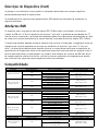
Indications
(Product codes TriMarkTD 13-12, TriMarkTD-2S-13-12, TriMarkTD 13-09, TriMarkTD-2S-13-09,
TriMarkTD 13-MR, TriMarkTD-2S-13-MR, TriMarkTD 36-12, TriMarkTD-2S-36-12, TriMarkTD 36-09
and TriMarkTD-2S-36-09.)
The ATEC TriMark biopsy site marker system is indicated for use to mark an open or percutaneous biopsy
site to radiographically mark the location of the biopsy site.
Contraindications
None known.
Device Description
The ATEC TriMark biopsy site marker system is a sterile, single use system comprised of a titanium marker
and a deployment device. The deployment device consists of a rigid cannula, plunger, rigid push rod and
handle. The ATEC TriMark biopsy site marker is located at the distal end of the deployment device. The
ATEC TriMark biopsy site marker system may be used with imaging guidance (e.g., stereotactic x-ray,
ultrasound and MRI). The titanium marker is classied as magnetic resonance (MRI) conditional at 3.0
Tesla eld strength or less. The marker, when present in a patient undergoing an MRI procedure at 3.0
Tesla or less, will not create an additional hazard or risk with respect to magnetic eld-related interactions,
movement/dislodgement, or heating.

Safety information for MRI procedures should be performed according to the following guidelines:
MRI Artifacts
Artifacts for the ATEC TriMark biopsy site marker have been characterized using a 1.5 Tesla MRI system
and T1-weighted, spin echo and gradient echo pulse sequences. Based on this information, imaging
quality may be slightly compromised if the area of interest is in the exact same area as the ATEC TriMark
biopsy site marker.
Artifact size is dependent on the type of pulse sequence used for imaging (larger for gradient echo pulse
sequences and smaller for spin echo and fast spin echo pulse sequences), the direction of the frequency
encoding direction (larger if the frequency encoding direction is perpendicular to the device and smaller
if it is parallel to the device), and the size of the eld of view. Positional errors and artifacts on images
will be smaller for MRI systems with lower static magnetic eld strengths using the same imaging
parameters as those operating at higher static magnetic eld strengths.
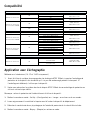
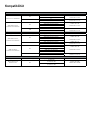
Compatibility
U/S
Approach Hand Piece Gauge Biopsy Site Access ATEC TriMark Device
Non Introducer Method
9G NA TriMark TD 13-09
TriMark TD-2S-13-09
NA
12G NA TriMark TD 13-12
TriMark TD-2S-13-12
NA
ATEC Outer Cannula
Introducer Method
9G
ATEC 0909-20 Outer Cannula
TriMark TD 13-09
TriMark TD-2S-13-09
ATEC 0909-12 Outer Cannula
ATEC 0912-20 Outer Cannula
ATEC 0912-12 Outer Cannula
12G ATEC 1209-20 Outer Cannula TriMark TD 13-12
TriMark TD-2S-13-12
ATEC 1212-20 Outer Cannula
STX
Approach Hand Piece Gauge Biopsy Site Access ATEC TriMark Device
ATEC Outer Cannula
Introducer Method
9G
ATEC 0909-20 Outer Cannula TriMark TD 13-09
TriMark TD-2S-13-09
ATEC 0909-12 Outer Cannula
ATEC 0912-20 Outer Cannula
ATEC 0912-12 Outer Cannula
12G ATEC 1209-20 Outer Cannula TriMark TD 13-12
TriMark TD-2S-13-12
ATEC 1212-20 Outer Cannula
ATEC Handpiece
Introducer Method
9G
ATEC 0909-20 Handpiece
TriMark TD 36-09
TriMark TD-2S-36-09
ATEC 0909-12 Handpiece
ATEC 0912-20 Handpiece
ATEC 0912-12 Handpiece
ATEC 0914-20 Handpiece
12G ATEC 1209-20 Handpiece TriMark TD 36-12
TriMark TS-2S-36-12
ATEC 1212-20 Handpiece
MRI
Approach Hand Piece Gauge Biopsy Site Access ATEC TriMark Device
ATEC Introducer
Sheath Method 9G
ILS 0914-20
ILS 0914-20-OB TriMark TD 13-MR
TriMark TD-2S-13-MR
ILS 0914-12
ILS 0914-12-OB

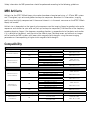
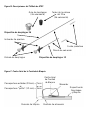
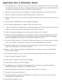
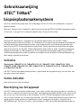
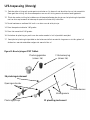
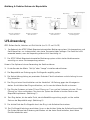
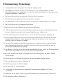
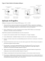
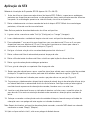
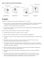
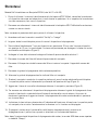
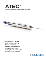
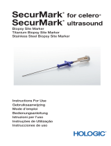
Cores Taken From
Beside the Lesion
Cores Taken From
Above the Lesion
Cores Taken From
Below the Lesion
Cores Taken Around
the Clock
Marker
Marker Marker
Marker
Biopsy Cavity
Biopsy Cavity Biopsy Cavity
Biopsy Cavity
Biopsy Deployment
Device Biopsy Deployment
Device
Biopsy Deployment
Device
Biopsy Deployment
Device
12
12 12
12
6
6
6
6
99
333
3
9
9
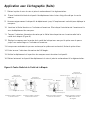
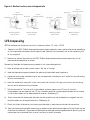
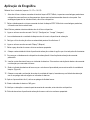
Ultrasound Application
Non Introducer Method (13-12 and 13-09 only)
1. Prior to use of the ATEC TriMark biopsy site marker system, inspect the protective packaging and
device to verify that neither has been damaged during shipment. If it appears that the packaging has
been compromised, do not use the device.
2. Carefully remove the ATEC TriMark biopsy site marker system from its protective packaging using
sterile technique.
Note: Remove tip protector prior to use of the device.
3. Turn or activate the console to “Set Up” or “Lavage” mode.
4. Lavage the biopsy cavity thoroughly before insertion of the deployment device.
5. Disconnect the saline line at the proximal end of the Y-Valve.
6. Turn or activate the console to “Biopsy” mode.
7. Remove the handpiece from the breast and properly dispose.
8. Place the distal end of the deployment device into the needle tract that was created by the
outer cannula.
9. Carefully advance the deployment device to the desired marker deployment location.
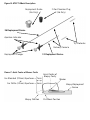
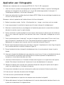
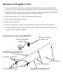
10. Locate the white directional arrow on the aperture indicator. This shows the orientation of the
marker aperture and the direction the marker will deploy.
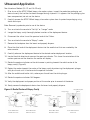
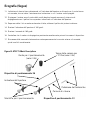
11. Rotate the aperture indicator so the white arrow is pointing towards the radial center of the
biopsy cavity. (Figure A)
12. Deploy the marker towards the center of the biopsy cavity by advancing the deployment plunger
with your thumb until it latches onto the aperture indicator.
13. After the audible and tactile click, release your thumb from the white plunger.
14. Rotate the aperture indicator 180 degrees.
15. Verify the deployment and proper position of the marker prior to removal of the device.
16. Slowly remove the deployment device from the breast and properly dispose.
Figure A: Radial Center of Biopsy Cavity

Ultrasound Application
ATEC Outer Cannula Introducer Method (13-12 and 13-09 only)
1. Prior to use of the ATEC TriMark biopsy site marker system, inspect the protective packaging and
device to verify that neither has been damaged during shipment. If it appears that the packaging has
been compromised, do not use the device.
2. Carefully remove the ATEC TriMark biopsy site marker system from its protective packaging using
sterile technique.
Note: Remove tip protector prior to use of the device.
3. Turn or activate the console to “Set Up” or “Lavage” mode.
4. Lavage the biopsy cavity thoroughly before insertion of the deployment device.
5. Disconnect the saline line at the proximal end of the Y-Valve and strip the line up to the hub.
6. While holding the hub rmly in one hand, rotate the handpiece 1/8 of a turn counter-clockwise
and pull-back to separate it from the outer cannula.
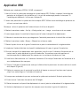
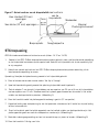
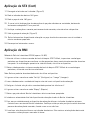
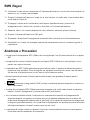
7. Pull back the hub 7mm for 20mm aperture devices or 3mm for 12mm aperture devices. This will
position the system to deploy the marker in the axial center of the biopsy cavity. (Figure C)
8. Rotate the hub so the white dot indicating needle aperture position is pointing towards the radial
center of the biopsy cavity. (Figure A)
9. Place the distal end of the deployment device into the outer cannula through the hub.
10. Carefully advance the deployment device until it reaches a denitive stop at the distal tip of the outer
cannula. Make sure this position is maintained throughout the deployment of the marker by holding
it in place with your off hand.
11. Locate the white directional arrow on the aperture indicator and line it up with the white dot of the
hub. This shows the orientation of the marker aperture and the direction the marker will deploy.
12. Deploy the marker towards the center of the biopsy cavity by advancing the deployment plunger with
your thumb until it latches onto the aperture indicator.
13. After the audible and tactile click, release your thumb from the white plunger.
14. Rotate the aperture indicator 180 degrees.
15. Rotate the hub 180 degrees.
16. Verify the deployment and proper position of the marker prior to removal of the device.
17. Slowly remove the deployment device and outer cannula/hub as one unit from the breast and
properly dispose.

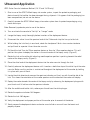
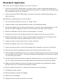
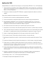
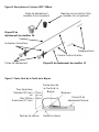
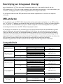
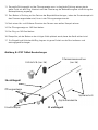
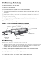
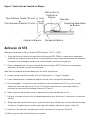
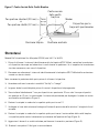
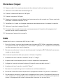
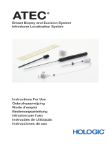
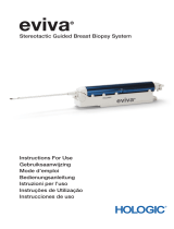
Figure B: ATEC TriMark Description
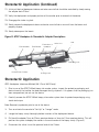
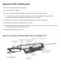
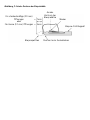
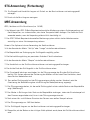
Figure C: Axial Center of Biopsy Cavity
For Standard (20mm) Apertures =
or
For Petite (12mm) Apertures =
7mm
3mm
Axial Center of
Biopsy Cavity
Biopsy/Deployment
Device
Pull-Back PositionBiopsy Position
Marker
Filter Chamber Plug
(36 Only)
Deployment Guide
(36 Only)
36 Deployment Device
Aperture Indicator
Deployment Plunger 13 Deployment Device
Delivery Cannula
Tip Protector

Stereotactic Application
ATEC Outer Cannula Introducer Method (13-12 and 13-09 only)
1. Prior to use of the ATEC TriMark biopsy site marker system, inspect the protective packaging and
device to verify that neither has been damaged during shipment. If it appears that the packaging has
been compromised, do not use the device.
2. Carefully remove the ATEC TriMark biopsy site marker system from its protective packaging using
sterile technique.
Note: Remove tip protector prior to use of the device.
3. Turn or activate the console to “Set Up” or “Lavage” mode.
4. Lavage the biopsy cavity thoroughly before insertion of the deployment device.
5. Pull back the adapter 7mm for 20mm aperture devices or 3mm for 12mm aperture devices. This will
position the system to deploy the marker in the axial center of the biopsy cavity. (Figure C)
6. Rotate the handpiece so the at surface is pointing towards 12 o’clock.
7. Disconnect the saline line at the proximal end of the Y-Valve and strip the line up to the hub.
8. Rotate the handpiece so the at surface is pointing towards the radial center of the biopsy cavity.
The at surface shows where the needle aperture is pointing. (Figure A)
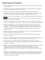
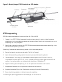
9. Engage one index ring lock to hold the hub in place. (Figure D)
10. Rotate the handpiece 1/8 of a turn counter-clockwise.
11. Unlock the retaining clamp, and pull the handpiece back to separate it from the hub. (Figure D)
12. Place the distal end of the deployment device into the outer cannula through the hub.
13. Carefully advance the deployment device until it reaches a denitive stop at the distal tip of the outer
cannula. Make sure this position is maintained throughout the deployment of the marker by holding
it in place with your off hand.
14. Locate the white directional arrow on the aperture indicator and line it up with the white dot of the
hub. This shows the orientation of the marker aperture and the direction the marker will deploy.
15. Deploy the marker towards the center of the biopsy cavity by advancing the deployment plunger
with your thumb until it latches onto the aperture indicator.
16. After the audible and tactile click, release your thumb from the white plunger.
17. Disengage the index ring lock.
18. Rotate the aperture indicator 180 degrees.
19. Rotate the hub 180 degrees.
20. Engage one index ring lock to hold the hub in place.

Stereotactic Application (Continued)
21. Initial pull-back of deployment device and outer cannula/hub should be controlled by slowly moving
the adapter back 20mm.
22. Verify the deployment and proper position of the marker prior to removal of the device.
23. Disengage the index ring lock.
24. Slowly remove the deployment device and outer cannula/hub as one unit from the breast and
properly dispose.
25. Slowly decompress the breast.
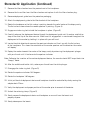
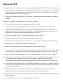
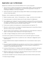
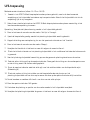
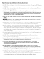
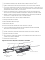
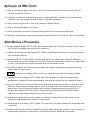
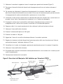
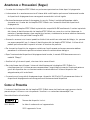
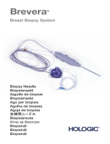
Figure D: ATEC Handpiece & Stereotactic Adapter Descriptions
Stereotactic Application
ATEC Handpiece Introducer Method (36-12 and 36-09 only)
1. Prior to use of the ATEC TriMark biopsy site marker system, inspect the protective packaging and
device to verify that neither has been damaged during shipment. If it appears that the packaging has
been compromised, do not use the device.
2. Carefully remove the ATEC TriMark biopsy site marker system from its protective packaging using
sterile technique.
Note: Remove tip protector prior to use of the device.
3. Turn or activate the console to “Set Up” or “Lavage” mode.
4. Lavage the biopsy cavity thoroughly before insertion of the deployment device.
5. Pull back the adapter 7mm for 20mm aperture devices or 3mm for 12mm aperture devices. This will
position the system to deploy the marker in the axial center of the biopsy cavity. (Figure C)
6. Disconnect the saline line at the proximal end of the Y-Valve.
Filter Chamber Filter Bracket Flat Surface of
Handpiece
Saline Line Hub
Index Ring Lock
Retaining Clamp
Cocking Lever
Proximal End of Y-Valve

Stereotactic Application (Continued)
7. Remove the lter chamber from the proximal end of the handpiece.
8. Remove the tissue lter from the lter chamber and replace it with the lter chamber plug.
9. Remove deployment guide from the protective packaging.
10. Attach the deployment guide to the lter bracket of the handpiece.
11. Rotate the handpiece so the at surface is pointing towards the radial center of the biopsy cavity.
The at surface shows where the needle aperture is pointing. (Figure A)
12. Engage one index ring lock to hold the handpiece in place. (Figure D)
13. Carefully advance the deployment device through the deployment guide until it reaches a denitive
stop at the distal tip of the outer cannula. Make sure this engagement is maintained throughout the
deployment of the marker by holding it in place with your off hand.
14. Locate the white directional arrow on the aperture indicator and line it up with the at surface
of the handpiece. This shows the orientation of the marker aperture and the direction the marker
will deploy.
15. Deploy the marker towards the center of the biopsy cavity by advancing the deployment plunger
with your thumb until it latches onto the aperture indicator.
Note: Following the insertion of the marker deployment device, the console should NOT be put back into
“biopsy” mode.
16. After the audible and tactile click, release your thumb from the white plunger.
17. Disengage the index ring lock. (Figure D)
18. Rotate the aperture indicator 180 degrees.
19. Rotate the handpiece 180 degrees.
20. Initial pull-back of deployment device and handpiece should be controlled by slowly moving the
adapter back 20mm.
21. Verify the deployment and proper position of the marker prior to removal of the device.
22. Unlock the retaining clamp. (Figure D)
23. Slowly remove the deployment device and handpiece as one unit from the breast and
properly dispose.
24. Slowly decompress the breast.

MRI Application
ATEC Introducer Sheath Method (13-MR only)
1. Prior to use of the ATEC TriMark biopsy site marker system, inspect the protective packaging and
device to verify that neither has been damaged during shipment. If it appears that the packaging has
been compromised, do not use the device.
2. Carefully remove the ATEC TriMark biopsy site marker system from its protective packaging using
sterile technique.
Note: Remove tip protector prior to use of the device.
3. Turn or activate the console to “Set Up” or “Lavage” mode.
4. Lavage the biopsy cavity thoroughly before insertion of the deployment device.
5. Disconnect the saline line at the proximal end of the Y-Valve.
6. Turn or activate the console to “Biopsy” mode.
7. Remove the handpiece from the Introducer Sheath and properly dispose.
8. Place the distal end of the deployment device through the Introducer Sheath.
9. Carefully advance the deployment device until the aperture indicator contacts the Introducer Sheath
hub. Make sure this position is maintained throughout the deployment of the marker by holding it in
place with your off hand.
10. Locate the white directional arrow on the aperture indicator. This shows the orientation of the marker
aperture and the direction the marker will deploy.
11. Rotate the aperture indicator so the white arrow is pointing towards the radial center of the
biopsy cavity. (Figure A)
12. Deploy the marker towards the center of the biopsy cavity by advancing the deployment plunger
with your thumb until it latches onto the aperture indicator.
13. After the audible and tactile click, release your thumb from the white plunger.
14. Rotate the aperture indicator 180 degrees.
15. Slowly remove the deployment device from the breast and properly dispose.
16. Verify the deployment and proper position of the marker prior to removal of the Introducer Sheath.
Warnings and Precautions
• TheATECTriMarkdeploymentdeviceisnotrecommendedforusewithintheboreofanMRImagnet.
• TheATECTriMarkbiopsysitemarkersystemisnotrecommendedforuseinpatientswithbreast
implants.

Warnings and Precautions (Continued)
• TheATECTriMarkprocedureshouldbeperformedonlybyphysicianshavingadequatetrainingand
familiarity with this procedure. Consult medical literature relative to techniques, complications, and
hazards prior to performance of any minimally invasive procedure.
• Thisdeviceshouldbeusedonlybyphysicianstrainedinopenorpercutaneousbiopsyprocedures.
• Caution: Federal (USA) law restricts this device to sale by or on the order of a physician.
• TheATECTriMarkbiopsysitemarkershouldbedeployedintothecavitycreatedduringthebiopsy
procedure. Deployment into tissue outside of the biopsy cavity is not recommended.
• Ifthedeploymentdeviceisdifculttoinsertorremovefromthebiopsydevicedonotapplyexcessive
force. Excessive force may cause damage or breakage of the deployment device which may result in
a portion of the deployment device being left behind in the patient. If the deployment device cannot
be easily removed from the biopsy device, remove the deployment device and the biopsy device as
one unit.
• Markerpositionrelativetoestablishedlandmarksmaychangeundermammographyuponsubsequent
breast compressions.
• TheATECTriMarkbiopsysitemarkerisnotintendedtoberepositionedorrecapturedafter
deployment.
• Excesshematomawithinthebiopsycavitycanleadtomarkeradhesiontothedeploymentdevice,
increasing the risk of marker drag out.
• Careshouldbetakentoavoiddamagingthecannula.Avoidoperatororinstrumentcontactwiththe
ATEC TriMark biopsy site marker or the distal end of the depployment device.
• TheimplantedATECTriMarkbiopsysitemarkerismagneticresonanceimaging(MRI)conditional.The
implanted ATEC TriMark biopsy site marker presents no additional risk to patient or operator from
magnetic forces, torque, heating, induced voltages, or movement, but it may affect MRI image
quality.
• Minimallyinvasiveinstrumentsandaccessoriesmanufacturedordistributedbycompaniesnot
authorized by Hologic, Inc., may not be compatible with the ATEC TriMark biopsy site marker system.
Use of such products may lead to unanticipated results and possible injury to the user or patient.
• Instrumentsordeviceswhichcomeintocontactwithbodilyuidsmayrequirespecialdisposal
handling to prevent biological contamination.
• Followingtheinsertionofthemarkerdeploymentdevice,theconsoleshouldNOTbeputintothe
“Biopsy” mode.
• Disposeofallopenedinstrumentswhetherusedorunused.
• Donotresterilizeand/orreusetheATECTriMarkbiopsysitemarkersystem.Resterilizationand/or
reuse may compromise the integrity of the instrument. This may lead to potential risks of failure of
the device to perform as intended, and/or cross-contamination associated with using inadequately
cleaned and sterilized devices.

Copyright © 2014 Hologic, Inc. Hologic, ATEC and TriMark are trademarks and/or registered trademarks of Hologic, Inc. in the United States and/or other
countries.
All rights reserved.
Warnings and Precautions (Continued)
• Ifdeploymentguideisnotusedfor36-09or36-12devices,damagemayoccurtothedeployment
device, resulting in device malfunction.
How Supplied
The ATEC TriMark biopsy site marker system is gamma sterilized and supplied preloaded for single patient
use. Discard into an appropriate container after use.
As Identied on Labels:
Number of Devices Enclosed.
YYYY-MM-DD Expiration date is represented by the following:
YYYY represents the year
MM represents the month
DD represents the day
For More Information
For more information on the ATEC TriMark biopsy site marker system, U.S. and Canadian
customers can contact the Hologic Customer Support at 1-877-887-8767 or [email protected].
International customers, please contact your local distributor.
AW-09782-001 Rev. 002

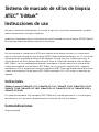
Sistema de marcado de sitios de biopsia
ATEC® TriMark®
Instrucciones de uso
Lea toda la información detenidamente. En caso de no seguir las instrucciones correctamente, se podrían
producir consecuencias quirúrgicas imprevistas.
Importante: Este paquete contiene instrucciones de uso del marcador de sitios de biopsia ATEC® TriMark®.
No se trata de material de referencia de técnicas quirúrgicas.
Una vez nalizada la intervención de ATEC para la obtención de biopsias de mama, el usuario podrá
elegir el sistema de marcado de sitios de biopsia ATEC TriMark diseñado por Hologic, Inc. En función del
tipo de aplicación (modalidad de obtención de imágenes) utilizada para guiar la biopsia de mama, el
usuario realizará uno de los procesos descritos para utilizar el sistema de marcado de sitios de biopsia
ATEC TriMark. Las tres modalidades de obtención de imágenes utilizadas para guiar la colocación del
sistema de marcado de sitios de biopsia ATEC TriMark son las siguientes: ecografía (U/S), radiografía
estereotáctica (STX) e imágenes por resonancia magnética (IRM). Existen dos métodos de colocación del
sistema de marcado de sitios de biopsia ATEC TriMark asociados a U/S y STX; ambos se describen por
separado.
Indicaciones
(Códigos de producto TriMarkTD 13-12, TriMarkTD-2S-13-12, TriMarkTD 13-09, TriMarkTD-2S-13-09,
TriMarkTD 13-MR, TriMarkTD-2S-13-MR, TriMarkTD 36-12, TriMarkTD-2S-36-12, TriMarkTD 36-09 y
TriMarkTD-2S-36-09).
El sistema de marcado de sitios de biopsia ATEC TriMark está indicado para marcar un sitio de biopsia
percutánea con el n de marcar radiográcamente la ubicación del sitio de la biopsia.
Contraindicaciones
Ninguna conocida.

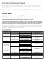
Descripción del Dispositivo
El marcador de sitios de biopsia ATEC TriMark es un sistema para su uso en un único paciente,
compuesto por un marcador de titanio y un dispositivo de colocación. El dispositivo de colocación está
formado por una cánula rígida, un émbolo, una varilla de empuje rígida y un asa. El marcador ATEC
TriMark se encuentra en el extremo distal del dispositivo de colocación. El sistema ATEC TriMark puede
utilizarse en métodos de obtención de imágenes, como las radiografías estereotácticas, las ecografías o
las IRM. El marcador de titanio se basa en imágenes por resonancia magnética (IRM) con una intensidad
de campo de 3,0 teslas o menos. El marcador, cuando se utilice en un paciente sometido a un
procedimiento de IRM de 3,0 teslas o menos, no supondrá ningún riesgo en lo que se reere a
interacciones con el campo magnético, a movimiento/descolocación o a calentamiento.
La información de seguridad para los procedimientos de IRM debe seguir las siguientes directrices:
Artefactos en IRM
Se han descrito artefactos en el marcador de sitios de biopsia ATEC TriMark al utilizar un sistema de IRM de
1,5 teslas y secuencias de impulsos de eco del gradiente y eco del espín potenciadas en T1. Por ello, la
calidad de imagen puede empeorar ligeramente si la región de interés está exactamente en la misma zona
que el marcador ATEC TriMark de sitios de biopsia.
El tamaño del artefacto depende del tipo de secuencia de impulsos utilizada (será mayor en las secuencias
de impulsos de eco del gradiente y menor en las secuencias de impulso de eco del espín y eco del espín
rápido), de la dirección de la codicación de frecuencia (será mayor si la dirección es perpendicular al
dispositivo y menor si es paralela), así como del tamaño del campo visual. Los errores de posición y los
artefactos de las imágenes serán menores en los sistemas de IRM con intensidades más bajas de campo
magnético estático que utilicen los mismos parámetros de obtención de imágenes que aquéllos con
intensidades más altas de campo magnético estático.

Compatibilidad
Aplicación ECO
Abordaje Sin Introductor (13-12 y 13-09 solamente)
1. Antes de utilizar el marcador de sitios de biopsia ATEC TriMark, revise el dispositivo y el paquete de
protección para comprobar que no se ha dañado durante el envío. Si parece que el envase ha sufrido
daños, no utilice el dispositivo.
2. Extraiga con cuidado el marcador ATEC TriMark de su paquete de protección mediante una técnica
aséptica.
Nota: retire el protector del extremo antes de utilizar el dispositivo.
3. Encienda o active la consola en modo de preparación o de lavado.
4. Lave minuciosamente la cavidad de la biopsia antes de insertar el dispositivo de colocación.
5. Desconecte la vía de solución salina del extremo proximal de la válvula Y.
6. Encienda o active la consola en modo de biopsia.
7. Extraiga la pieza de mano de la mama y deséchela de forma adecuada.
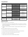
U/S
Método de abordaje Calibrador de mano Acceso al sitio biopsia Dispositivo TriMark™ de ATEC
Abordaje sin introductor
9G No procede TriMark TD 13-09
TriMark TD-2S-13-09
No procede
12G No procede TriMark TD 13-12
TriMark TD-2S-13-12
No procede
Abordaje mediante un
introductor constituido por
una cánula externa de ATEC®
9G
Cánula externa ATEC 0909-20
TriMark TD 13-09
TriMark TD-2S-13-09
Cánula externa ATEC 0909-12
Cánula externa ATEC 0912-20
Cánula externa ATEC 0912-12
12G Cánula externa ATEC 1209-20 TriMark TD 13-12
TriMark TD-2S-13-12
Cánula externa ATEC 1212-20
STX
Método de abordajo Calibrador de mano Acceso al sitio biopsia Dispositivo TriMark™ de ATEC
Abordaje mediante un
introductor constituido por
una cánula externa de ATEC®
9G
Cánula externa ATEC 0909-20 TriMark TD 13-09
TriMark TD-2S-13-09
Cánula externa ATEC 0909-12
Cánula externa ATEC 0912-20
Cánula externa ATEC 0912-12
12G Cánula externa ATEC 0909-20 TriMark TD 13-12
TriMark TD-2S-13-12
Cánula externa ATEC 0912-20
Abordaje mediante un
introductor constituido por
una pieza de mano ATEC®
9G
Pieza de mano ATEC 0909-20
TriMark TD 36-09
TriMark TD-2S-36-09
Pieza de mano ATEC 0909-12
Pieza de mano ATEC 0912-20
Pieza de mano ATEC 0912-12
Pieza de mano ATEC 0914-20
12G Pieza de mano ATEC 1209-20 TriMark TD 36-12
TriMark TS-2S-36-12
Pieza de mano ATEC 1212-20
MRI
Método de abordajo Calibrador de mano Acceso al sitio biopsia Dispositivo TriMark™ de ATEC
ATEC Introducer
Sheath Method 9G
ILS 0914-20
ILS 0914-20-OB TriMark TD 13-MR
TriMark TD-2S-13-MR
ILS 0914-12
ILS 0914-12-OB

Aplicación ECO (Continuación)
8. Introduzca el extremo distal del dispositivo de colocación en la vía de la aguja creada por la cánula
externa.
9. Haga avanzar cuidadosamente el dispositivo de colocación hasta situarlo en la ubicación deseada para
el marcador.
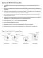
10. Sitúe la echa blanca de dirección en el indicador de apertura. De esta forma, se indica la orientación
de la apertura del marcador y la dirección en la que éste se colocará.
11. Gire el indicador de apertura de tal manera que la echa blanca apunte hacia el centro radial de la
cavidad de la biopsia. (Figura A)
12. Coloque el marcador orientado hacia el centro de la cavidad de la biopsia haciendo avanzar el émbolo
de colocación con el pulgar hasta que encaje en el indicador de apertura.
13. Cuando oiga y note un “clic”, retire el pulgar del émbolo blanco.
14. Gire el indicador de apertura 180 grados.
15. Compruebe la posición y la colocación del marcador antes de retirar el dispositivo.
16. Extraiga lentamente el dispositivo de colocación de la mama y deséchelo de forma adecuada.
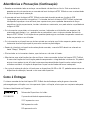
Figura A: Centro Radial de la Cavidad de Biopsia
Cilindros extraídos del
costado de la lesión
Cilindros extraídos por
encima de la lesión
Cilindros extraídos por
debajo de la lesión
Cilindros extraídos
circunferencialmente
Marcador
Marcador Marcador
Marcador
Cavidad de biopsia
Cavidad de
biopsia Cavidad de biopsia
Cavidad de biopsia
Dispositivo de
Despliegue y
Biopsia Dispositivo de
Despliegue y
Biopsia
Dispositivo de
Despliegue y
Biopsia
Dispositivo de
Despliegue y Biopsia
12
12 12
12
6
6
6
6
99
333
3
9
9

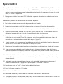
Aplicación ECO
Abordaje Mediante un Introductor Constituido por una Cánula Externa ATEC® (13-12 y 13-09 solamente)
1. Antes de utilizar el marcador de sitios de biopsia ATEC TriMark, revise el dispositivo y el paquete de
protección para comprobar que no se ha dañado durante el envío. Si parece que el envase ha sufrido
daños, no utilice el dispositivo.
2. Extraiga con cuidado el marcador ATEC TriMark de su paquete de protección mediante una técnica
aséptica.
Nota: retire el protector del extremo antes de utilizar el dispositivo.
3. Encienda o active la consola en modo de preparación o de lavado.
4. Lave minuciosamente la cavidad de la biopsia antes de insertar el dispositivo de colocación.
5. Desconecte la vía de solución salina del extremo proximal de la válvula Y y retírela hasta el conector.
6. Sujetando rmemente el conector con una mano, gire la pieza de mano 1/8 de vuelta en dirección
contraria a las agujas del reloj y tire de ella para separarla de la cánula externa.
7. Haga retroceder el conector 7 mm en los dispositivos de apertura de 20 mm, o 3 mm en los
dispositivos de apertura de 12 mm. De esta forma, el sistema quedará dispuesto para colocar el
marcador en el centro axial de la cavidad de la biopsia. (Figura C)
8. Gire el conector de tal manera que el punto blanco que indica la posición de la apertura de la aguja
apunte hacia el centro radial de la cavidad de la biopsia. (Figura A)
9. Introduzca el extremo distal del dispositivo de colocación en la cánula externa a través del conector.
10. Haga avanzar con cuidado el dispositivo de colocación hasta que alcance un tope denitivo en el
extremo distal de la cánula externa. Asegúrese de mantener esta posición durante todo el proceso de
colocación del marcador, sujetándolo con su mano libre.
11. Sitúe la echa blanca de dirección en el indicador de apertura y alinéela con el punto blanco del
conector. De esta forma, se indica la orientación de la apertura del marcador y la dirección en la que
éste se colocará.
12. Coloque el marcador orientado hacia el centro de la cavidad de la biopsia haciendo avanzar el
émbolo de colocación con el pulgar hasta que encaje en el indicador de apertura.
13. Cuando oiga y note un “clic”, retire el pulgar del émbolo blanco.
14. Gire el indicador de apertura 180 grados.
15. Gire el conector 180 grados.
16. Compruebe la posición y la colocación del marcador antes de retirar el dispositivo.
17. Extraiga lentamente el dispositivo de colocación y la cánula externa o el conector como si fuesen una
sola unidad y deséchelos de forma adecuada.

Figura B: Descripciones del TriMark de ATEC
Figura C: Centro Axial de la Cavidad de Biopsia
Para aperturas estándar (20mm) =
or
Para aperturas “petite” (12 mm) =
7mm
3mm
Centro Axial
de Cavidad
de Biopsia
Dispositivo de
Despliegue
y Biopsia
Posición de retracciónPosición de biopsia
Marcador
Tapón de la cámara
del ltro
(36 solamente)
Guía de despliegue
(36 solamente)
Dispositivo de despilegue 36
Indicador de apertura
Émbolo de despliegue
Funda protectora
Dispositivo de despilegue 13
Cánula de colcación

Aplicación STX
Abordaje Mediante un Introductor Constituido por una Cánula Externa ATEC® (13-12 y 13-09 solamente)
1. Antes de utilizar el marcador de sitios de biopsia ATEC TriMark, revise el dispositivo y el paquete de
protección para comprobar que no se ha dañado durante el envío. Si parece que el envase ha sufrido
daños, no utilice el dispositivo.
2. Extraiga con cuidado el marcador ATEC TriMark de su paquete de protección mediante una técnica
aséptica.
Nota: retire el protector del extremo antes de utilizar el dispositivo.
3. Encienda o active la consola en modo de preparación o de lavado.
4. Lave minuciosamente la cavidad de la biopsia antes de insertar el dispositivo de colocación.
5. Haga retroceder el adaptador 7 mm en los dispositivos de apertura de 20 mm, o 3 mm en los
dispositivos de apertura de 12 mm. De esta forma, el sistema quedará dispuesto para colocar el
marcador en el centro axial de la cavidad de la biopsia. (Figura C)
6. Gire la pieza de mano de tal manera que la supercie plana apunte hacia arriba.
7. Desconecte la vía de solución salina del extremo proximal de la válvula Y y retírela hasta el conector.
8. Gire la pieza de mano de tal modo que la supercie plana apunte hacia el centro radial de la cavidad
de la biopsia. La supercie plana muestra hacia dónde apunta la apertura de la aguja. (Figura A)
9. Acople un dispositivo de bloqueo del anillo índice para mantener jo el conector. (Figura D)
10. Gire la pieza de mano 1/8 de vuelta en dirección contraria a las agujas del reloj.
11. Desbloquee el dispositivo de sujeción y tire de la pieza de mano para separarla del conector. (Figura
D)
12. Introduzca el extremo distal del dispositivo de colocación en la cánula externa a través del conector.
13. Haga avanzar con cuidado el dispositivo de colocación hasta que alcance un tope denitivo en el
extremo distal de la cánula externa. Asegúrese de mantener esta posición durante todo el proceso de
colocación del marcador, sujetándolo con su mano libre.
14. Sitúe la echa blanca de dirección en el indicador de apertura y alinéela con el punto blanco del
conector. De esta forma, se indica la orientación de la apertura del marcador y la dirección en la que
éste se colocará.
15. Coloque el marcador orientado hacia el centro de la cavidad de la biopsia haciendo avanzar el
émbolo de colocación con el pulgar hasta que encaje en el indicador de apertura.
16. Cuando oiga y note un “clic”, retire el pulgar del émbolo blanco.
17. Desacople el dispositivo de bloqueo del anillo índice.

Aplicación STX (Continuación)
18. Gire el indicador de apertura 180 grados.
19. Gire el conector 180 grados.
20. Acople un dispositivo de bloqueo del anillo índice para mantener jo el conector.
21. La retracción inicial del dispositivo de colocación y de la cánula externa o el conector debe
controlarse desplazando el adaptador lentamente 20 mm hacia atrás.
22. Compruebe la posición y la colocación del marcador antes de retirar el dispositivo.
23. Desacople el dispositivo de bloqueo del anillo índice.
24. Extraiga lentamente el dispositivo de colocación y la cánula externa o el conector como si fuesen una
sola unidad y deséchelos de forma adecuada.
25. Descomprima lentamente la mama.
Figura D: Descripciones de la Pieza de Mano ATEC® y del Adaptador STX
Cámara del ltro Abrazadera del
ltro
Supercie plana de
lapieza de mano
Vía de solución salina Conector
Dispositivo de bloqueo
del anillo índice
Dispositivo de
sujeción
Palanca de
inclinación
Extremo proximal de la
válvula Y
Seite wird geladen ...
Seite wird geladen ...
Seite wird geladen ...
Seite wird geladen ...
Seite wird geladen ...
Seite wird geladen ...
Seite wird geladen ...
Seite wird geladen ...
Seite wird geladen ...
Seite wird geladen ...
Seite wird geladen ...
Seite wird geladen ...
Seite wird geladen ...
Seite wird geladen ...
Seite wird geladen ...
Seite wird geladen ...
Seite wird geladen ...
Seite wird geladen ...
Seite wird geladen ...
Seite wird geladen ...
Seite wird geladen ...
Seite wird geladen ...
Seite wird geladen ...
Seite wird geladen ...
Seite wird geladen ...
Seite wird geladen ...
Seite wird geladen ...
Seite wird geladen ...
Seite wird geladen ...
Seite wird geladen ...
Seite wird geladen ...
Seite wird geladen ...
Seite wird geladen ...
Seite wird geladen ...
Seite wird geladen ...
Seite wird geladen ...
Seite wird geladen ...
Seite wird geladen ...
Seite wird geladen ...
Seite wird geladen ...
Seite wird geladen ...
Seite wird geladen ...
Seite wird geladen ...
Seite wird geladen ...
Seite wird geladen ...
Seite wird geladen ...
Seite wird geladen ...
Seite wird geladen ...
Seite wird geladen ...
Seite wird geladen ...
Seite wird geladen ...
Seite wird geladen ...
Seite wird geladen ...
Seite wird geladen ...
Seite wird geladen ...
Seite wird geladen ...
Seite wird geladen ...
Seite wird geladen ...
Seite wird geladen ...
Seite wird geladen ...
Seite wird geladen ...
Seite wird geladen ...
Seite wird geladen ...
Seite wird geladen ...
Seite wird geladen ...
Seite wird geladen ...
Seite wird geladen ...
-
 1
1
-
 2
2
-
 3
3
-
 4
4
-
 5
5
-
 6
6
-
 7
7
-
 8
8
-
 9
9
-
 10
10
-
 11
11
-
 12
12
-
 13
13
-
 14
14
-
 15
15
-
 16
16
-
 17
17
-
 18
18
-
 19
19
-
 20
20
-
 21
21
-
 22
22
-
 23
23
-
 24
24
-
 25
25
-
 26
26
-
 27
27
-
 28
28
-
 29
29
-
 30
30
-
 31
31
-
 32
32
-
 33
33
-
 34
34
-
 35
35
-
 36
36
-
 37
37
-
 38
38
-
 39
39
-
 40
40
-
 41
41
-
 42
42
-
 43
43
-
 44
44
-
 45
45
-
 46
46
-
 47
47
-
 48
48
-
 49
49
-
 50
50
-
 51
51
-
 52
52
-
 53
53
-
 54
54
-
 55
55
-
 56
56
-
 57
57
-
 58
58
-
 59
59
-
 60
60
-
 61
61
-
 62
62
-
 63
63
-
 64
64
-
 65
65
-
 66
66
-
 67
67
-
 68
68
-
 69
69
-
 70
70
-
 71
71
-
 72
72
-
 73
73
-
 74
74
-
 75
75
-
 76
76
-
 77
77
-
 78
78
-
 79
79
-
 80
80
-
 81
81
-
 82
82
-
 83
83
-
 84
84
-
 85
85
-
 86
86
-
 87
87


in anderen Sprachen
- français: Hologic TriMark Mode d'emploi
- español: Hologic TriMark Instrucciones de operación
- italiano: Hologic TriMark Istruzioni per l'uso
- Nederlands: Hologic TriMark Handleiding
- português: Hologic TriMark Instruções de operação
Verwandte Artikel
-
 Hologic SecurMark Bedienungsanleitung
-
 Hologic ATEC Breast Biopsy and Excision System Ultrasound Introducer Bedienungsanleitung
-
 Hologic CeleroMark Bedienungsanleitung
-
 Hologic TriMark Bedienungsanleitung
-
 Hologic ATEC Handpiece Bedienungsanleitung
-
 Hologic ATEC Breast Biopsy and Excision System Introducer Localization System Bedienungsanleitung
-
 Hologic Brevera Breast Biopsy System Biopsy Needle Bedienungsanleitung
-
 Hologic SecurMark Bedienungsanleitung
-
 Hologic SecurMark Bedienungsanleitung
-
 Hologic Eviva Stereotactic Guided Breast Biopsy System Bedienungsanleitung


