De Dietrich DHG556XP Bedienungsanleitung
- Kategorie
- Dunstabzugshauben
- Typ
- Bedienungsanleitung

Guide d’utilisation
Instructions for installation and use
Montage- und gebrauchsanweisung
Istruzioni per l'installazione e l’uso
Instrucciones para instalación y uso
Instruções de instalação y utilização
Aanwijzing voor gebruik en installatie
DHG556XP - DHG576XP
DHG577XP - DHG589XP
DHG560XP - DHG570XP

2
HOTTE DE DIETRICH
Chère Cliente, Cher Client,
Vous venez d’acquérir une hotte DE DIETRICH et nous vous en remercions.
Nos équipes de recherche ont conçu pour vous une nouvelle génération d’appareils, qui par leur
qualité, leur design et leurs évolutions technologiques en font des produits d’exception et révèle
un savoir-faire unique.
Avec des lignes modernes et raffinées, votre nouvelle hotte DE DIETRICH s’intègre
harmonieusement dans votre cuisine et allie parfaitement la maîtrise technologique, les
performances d’aspiration, et le luxe esthétique.
Vous trouverez également dans la gamme des produits DE DIETRICH, un vaste choix de fours
encastrables, tables de cuisson, de lave-vaisselle, de fours micro-ondes et de réfrigérateurs
intégrables, que vous pourrez coordonner à votre nouvelle hotte DE DIETRICH.
Bien entendu, dans un souci permanent de satisfaire au mieux vos exigences vis à vis de nos
produits, notre service consommateurs est à votre disposition et à votre écoute pour répondre à
toutes vos questions ou suggestions (coordonnées à la fin de ce livret).
Grâce à ces “nouveaux objets de valeurs” qui nous servent de repère dans nos vies de tous les
jours, DE DIETRICH, référence de l’excellence, est une véritable invitation à un nouvel art de
vivre.
La Marque DE DIETRICH.

3
IMPORTANT; AVANT TOUTE OPERATION D’INSTALLATION ET UTILISATION, VEUILLEZ
PRENDRE BONNE NOTE DES INSTRUCTIONS SUIVANTES
La distance minimum entre la surface de support des casseroles sur le plan de cuisson et la partie inférieure de la hotte doit être
de 65 cm. Si les consignes, pour l’installation du plan de cuisson, indiquent une plus grande distance, il faut en tenir compte.
L'air aspiré ne doit pas être canalisé dans un conduit qui est utilisé pour évacuer les fumées produites par des appareils alimentés
par des sources d'énergies autres que l'énergie électrique (installations de chauffage central, radiateurs, chauffe-eau, etc.).
Pour évacuer l'air qui doit être éliminé respectez les prescriptions des autorités compétentes. De plus l'air qui doit être évacué
ne doit pas être déchargé dans une cavité du mur, à moins que cette cavité soit prévue pour ce but.
Prévoyez une aération de la pièce adéquate quand une hotte et des appareils alimentés par une énergie autre que l'énergie
électrique (poêle à gaz, à huile, à charbon etc.) sont utilisés en même temps. En effet, en évacuant l'air, la hotte pourrait créer
une dépression dans la pièce. La pression négative de la pièce ne doit pas dépasser 0,04mbar, évitant ainsi que la source de
chaleur provoque un appel des gaz qui doivent être évacués. Il est donc nécessaire d'équiper la pièce de prises d'air alimentant
un flux d'air frais constant.
Contrôler la plaque des caractéristiques techniques se trouvant à l’intérieur de l’appareil; si le symbole (
) figure sur la plaque
suivre les instructions suivantes: cet appareil est construit pour appartenir à la classe d’isolation II ; il ne doit donc pas être relié
à la terre.
Contrôler la plaque des caractéristiques techniques se trouvant à l’intérieur de l’appareil; si le symbole (
) NE figure pas sur
la plaque suivre les instructions suivantes: ATTENTION: cet appareil doit être relié à la terre. Lors du raccordement électrique
s’assurer que la prise de courant est équipée d’une connexion de mise à la terre.
Lors du raccordement électrique assurez-vous que les valeurs de tension correspondent à celles qui sont indiquées sur la plaque
des caractéristiques de l’appareil, qui se trouve à l'intérieur de celui-ci. Si votre appareil, n'a pas de câble flexible qui ne peut
pas être séparé ni de prise, ou bien d'autre dispositif qui garantisse le débranchement de tous les pôles du réseau, avec une
distance d'ouverture entre les contacts d'au moins 3 mm, ces dispositifs de séparation du réseau doivent alors être prévus dans
l'installation fixe. Si votre appareil est muni d’un câble d’alimentation, positionner l’appareil de manière à ce que la fiche soit
accessible.
Avant de procéder à une opération d’entretien ou de nettoyage quelconque, débranchez l’appareil.
ATTENTION: ces appareils doivent être reliés à la terre.
UTILISATION
Evitez d'utiliser des matériaux qui provoquent des flammes à proximité de l'appareil.
Dans le cas de fritures, faites tout particulièrement attention au danger d’incendie que représentent les huiles et les corps gras.
A cause de son inflammabilité l’huile usagée est particulièrement dangereuse. N'utilisez pas de grils électriques découverts.
Pour éviter des risques d'incendie possibles suivez les instructions données concernant le nettoyage des filtres à graisse et sur
la façon d'enlever des dépôts éventuels de graisse sur l'appareil.
ENTRETIEN
Un entretien soigné est une garantie de bon fonctionnement et de bon rendement de votre appareil dans le temps.
Faites beaucoup d’ attention surtout aux filtres antigraisse et nettoyez-les périodiquement (au moins tous les deux mois). Retirez
les filtres à graisse et lavez-les avec un détergent liquide à la main ou dans le lave-vaisselle.(voir châpitre Entretien).
L’élimination, d’éventuels dépôts de graisse sur l’appareil, doit être effectuée en fonction de l’utilisation de ce dernier (au moins
tous les 2 mois). Il faut éviter d’utiliser des produits contenant des abrasifs ou des corrosifs. Pour le nettoyage extérieur des
appareils peints, utiliser un chiffon mouillé avec de l’eau tiède et un détersif neutre. Pour le nettoyage extérieur des appareils
en acier, en cuivre et en laiton il est conseillé d’utiliser des produits spécifiques et de suivre les instructions fournies sur le produit.
Pour le nettoyage de l’intérieur de l’appareil, utiliser un chiffon (ou un pinceau) imbibé d’alcool dénaturé.
FRANCAIS

4
DESCRIPTION DES APPAREILS
Les descriptions et caractéristiques figurant sur ce document sont données à titre d'information et non d'engagements. En
effet, soucieux de la qualité de nos produits, nous nous réservons le droit d'effectuer, sans préavis, toutes modifications ou
améliorations.
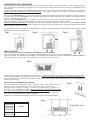
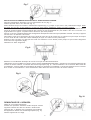
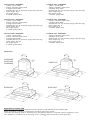
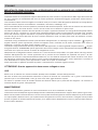
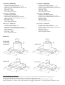
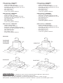
La hotte pourra être installée en version Recyclage, Evacuation ou avec moteur extérieur, selon le modèle que vous achèterez.
Modèles DHG556XP-DHG576XP-DHG577XP-DHG589: ces modèles peuvent être installés en version Recyclage ou
Evacuation, selon vos besoins.
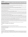
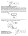
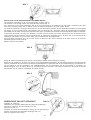
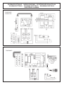
Dans la version Recyclage (Fig. 1), l’air et les vapeurs convoyés par l’appareil sont épurés par le filtre à charbon et remis en
circulation dans la pièce. ATTENTION: Pour la version Recyclage vous devez utiliser le filtre à charbon qui purifie l'air qui est
remis en circulation dans la pièce.
Dans la version Evacuation (Fig. 2), les vapeurs et les odeurs de la cuisine sont convoyées directement à l’extérieur par un
tuyau d’évacuation à travers la paroi/plafond. Il n’est donc pas nécessaire d’utiliser le filtre à charbon.
Modèles DHG560XP-DHG570XP: ces modèles peuvent être installés uniquement dans la version avec moteur externe
(Fig.3); c’est-à-dire qu’il faut relier unmoteur extérieur à l’appareil, qui opérera séparément, en utilisant l’appareil comme base
de raccordement de l’air à évacuer.
Cet appareil est conforme à l'arrêté du 16.08.89 relatif à la limitation des perturbations radioélectriques (Directive CEE n. 76.889
modifiée par la Directive CEE 87.308).
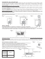
INSTALLATION
Il est conseillé de confier les opérations d’installation à des spécialistes.
Lire attentissement les indications au paragraphe “IMPORTANT” de la page n.3 de la notice d’utilisation.
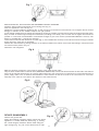
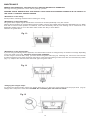
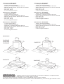
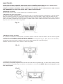
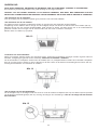
Avant de procéder aux opérations de montage, pour manoeuvrer plus aisément l’appareil, démontez les filtres à graisse: à
l'aide de la poignée, pousser l’arrêt vers l’intérieur et tirer le filtre vers le bas (Fig. 4).
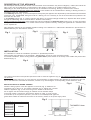
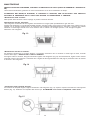
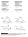
Faites le trou nécessaire afin d’insérer l’appareil (Fig. 5).
La base inférieure du meuble doit avoir une épaisseur de 16 mm.
Contrôler que les ailettes de fixation (Fig. 6) au meuble suspendu sont placées à une hauteur appropriée à l’épaisseur du
bas de ce dernier. Si cette distance est inférieure à l’épaisseur, il faut l’augmenter en dévissant les 2 vis correspondantes à
l’intérieur de l’appareil.
INSTALLATION EN VERSION RECYCLAGE
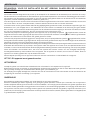
Prévoyez l’alimentation électrique. Insérez l’appareil dans le trou effectué (Fig. 5).
Prévoyez le trou d’évacuation de l’air au sommet de votre placard (Fig.1).
Serrez les deux vis qui se trouvent à l’interieur de l’appareil (Fig. 7), jusqu’à ce
que celui ci soit parfaitement intégré.
Eviter de serrer trop fort les vis de manière
à ce que les petits étriers métalliques restent en bonne position.
Raccordez le tuyau de raccordement à la bride de sortie de l’appareil (le tuyau
n’est pas fourni). Remontez les filtres antigraisse.
Effectuez le raccordement électrique de la hotte au moyen du câble d'alimentation.
EPAISSEUR 16mm
Fig. 1
Fig. 2
Fig. 4
Fig. 5
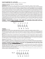
MODELS A
DHG556XP
DHG576XP
DHG589XP
DHG560XP
DHG577XP
DHG570XP
690mm
490mm
Fig. 6
Fig. 3

5
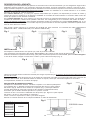
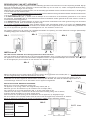
INSTALLATION EN VERSION EVACUATION ET AVEC MOTEUR EXTERNE
Prévoyez l’alimentation électrique et le trou d’évacuation de l’air (Fig. 2).
Insérez l’appareil dans le trou effectué (Fig. 5).
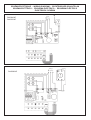
Serrez les deux vis qui se trouvent à l’interieur de l’appareil (Fig. 7), jusqu’à ce que celui ci soit parfaitement intégré.
Eviter
de serrer trop fort les vis de manière à ce que les petits étriers métalliques restent en bonne position.
Pour obtenir des conditions optimales, vous devez employer un tuyau d’évacuation qui ait une longueur suffisante avec le
moins de courbes possible (l'angle maximum des courbes ne doit pas dépasser 90°). Sa matière doit être conforme à la
réglementation en vigueur. La partie interne doit être le plus lisse possible.
De plus, nous vous conseillons d’éviter des changements brusques de section du tuyau (diamètre conseillé: 150 mm). L’appareil
est livré avec un réducteur 150-125cm.
Raccordez le tuyau pour l’évacuation de l’air à la bride de sortie de l’air de la hotte (Fig. 2): utilisez un tuyau souple et bloquez
le sur la sortie de l’air à l’aide d’un collier métallique (le tuyau et le collier ne sont pas fournis).
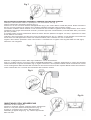
Enlevez le filtre à charbon, en appuyant sur l’arrêt vers l’intérieur et en le faisant pivoter jusqu’à ce que les deux languettes
sortent de leurs logements (Fig.8).
Remontez les filtres antigraisse.
Effectuez le raccordement électrique de la hotte au moyen du câble d'alimentation.
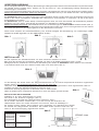
Uniquement pour les modèles en version moteur externe (DHG560XP-DHG570XP) : effectuez le raccordement électrique de
la hotte au moteur extérieur, en utilisant des borniers appropriés (Fig. 9) : enlevez l’élément A et le couvercle B du boîtier de
raccordement. Fixez le câble de raccordement du moteur au boîtier de raccordement C. Remontez l’élément A et le couvercle
B du boîtier de raccordement. L’autre extrêmité du câble devra être fixée au bornier du moteur extérieur.
DEMONTAGE DE L’APPAREIL
Retirer le ou les filtres antigraisse.
Pendant les opérations suivantes veuillez toujours soutenir
l’appareil. Dévisser les deux vis situées à l’intérieur de
l’appareil (Fig. 7); déplacer les 2 languettes vers l’intérieur
de l’appareil en utilisant les entailles appropriées (Fig. 10);
extraire l’appareil de son siège.
Fig. 7
Fig. 8
Fig. 9
Fig. 10
A
C
B

6
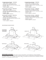
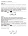
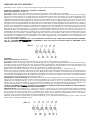
FONCTIONNEMENT DE L’APPAREIL
Selon les modèles, l’appareil est muni des types suivants de commandes:
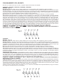
DHG556XP, DHG576XP, DHG577XP, DHG560XP, DHG570XP
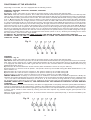
COMMANDES - Fig. 11:
A) ON/OFF lampes. Cette touche s’utilise également pour la fonction alarme filtres à graisse et filtres à charbon.
Alarme filtres : Après 30h de fonctionnement, le témoin lumineux L1 s’allume et reste allumé (c’est le moment de nettoyer
les filtres à graisse). Après 120h de fonctionnement, le témoin lumineux L1 s’allume et reste allumé (c’est le moment de
remplacer les filtres à charbon si la hotte en est équipée). L’alarme des filtres s’active UNIQUEMENT avec le moteur ARRETE.
L’alarme des filtres s’annule (remise à zéro du compteur HORAIRE) en maintenant la touche A enfoncée pendant 2". B) Appuyer
sur la touche B pour actionner le moteur à la première vitesse. La vitesse est signalée par le témoin lumineux L2 allumé. En
la maintenant enfoncée pendant 2" le moteur s’arrête. En appuyant une seule fois, avec le témoin lumineux allumé, on active
la fonction “Arrêt temporisé” (le moteur de l’appareil s’arrête après 5 minutes) signalée par le témoin lumineux qui clignote. Pour
désactiver la fonction “Arrêt temporisé” appuyer encore une seule fois. C) Appuyer sur la touche C pour actionner le moteur
en deuxième vitesse. La vitesse est signalée par le témoin lumineux L3 allumé. En appuyant une seule fois, avec le témoin
lumineux allumé, on active la fonction “Arrêt temporisé” (le moteur de l’appareil s’arrête après 5 minutes) signalée par le témoin
lumineux qui clignote. Pour désactiver la fonction “Arrêt temporisé” appuyer encore une seule fois. D) Appuyer sur la touche
D pour actionner le moteur en troisième vitesse. La vitesse est signalée par le témoin lumineux L4 allumé. En appuyant une
seule fois, avec le témoin lumineux allumé, on active la fonction “Arrêt temporisé” (le moteur de l’appareil s’arrête après 5
minutes) signalée par le témoin lumineux qui clignote. Pour désactiver la fonction “Arrêt temporisé” appuyer encore une seule
fois. E) Appuyer sur la touche E pour actionner le moteur en quatrième vitesse. La vitesse est signalée par le témoin lumineux
L5 allumé. En appuyant une seule fois, avec le témoin lumineux allumé, on active la fonction “Arrêt temporisé” (le moteur de
l’appareil s’arrête après 5 minutes) signalée par le témoin lumineux qui clignote. Pour désactiver la fonction “Arrêt temporisé”
appuyer encore une seule fois.
ATTENTION : EN ACTIONNANT LA FONCTION “ARRÊT TEMPORISÉ”, LE MOTEUR S’ETEINT APRÈS 5 MINUTES.
ATTENTION : QUAND LE
TEMOIN LUMINEUX L1 S’ALLUME IL EST NECESSAIRE DE NETTOYER LES FILTRES
ANTIGRAISSE OU DE REMPLACER LE FILTRE CHARBON.
DHG589XP
COMMANDES - Fig. 12:
A) ON/OFF lampes. Cette touche s’utilise également pour la fonction alarme filtres à graisse et filtres à charbon.
Alarme filtres : Après 30h de fonctionnement, le témoin lumineux L1 s’allume et reste allumé pendant 30" (c’est le moment
de nettoyer les filtres à graisse). Après 120h de fonctionnement, le témoin lumineux L1 s’allume et reste allumé pendant 30"
(c’est le moment de remplacer les filtres à charbon si la hotte en est équipée). L’alarme des filtres s’active UNIQUEMENT avec
le moteur ARRETE. L’alarme des filtres s’annule (remise à zéro du compteur HORAIRE) en maintenant la touche A enfoncée
pendant 2".
B) La touche B permet d’activer ou de désactiver la fonction automatique (une fois le capteur activé, le témoin L2 s’allume).
C) Appuyer sur la touche C pour actionner le moteur à la première vitesse. La vitesse est signalée par le témoin lumineux L3
allumé. En la maintenant enfoncée pendant 2" le moteur s’arrête. D) Appuyer sur la touche D pour actionner le moteur en
deuxième vitesse. La vitesse est signalée par le témoin lumineux L4 allumé. E) Appuyer sur la touche E pour actionner le moteur
en troisième vitesse. La vitesse est signalée par le témoin lumineux L5 allumé. F) Appuyer sur la touche F pour actionner le
moteur en quatrième vitesse. La vitesse est signalée par le témoin lumineux L6 allumé.
SENSIBILITE DU CAPTEUR : la sensibilité du AUTO peut être adaptée aux exigences propres.
Modifier la sensibilité, en appuyant en même temps sur les touches A et B. La sensibilité préfixée grâce aux 4 témoins L3,
L4, L5, L6 clignotants s’affiche. Fixez la sensibilité désirée, en utilisant les touches C, D, E ou F (touche C sensibilité minimale,
touche F sensibilité maximale). Fixez une sensibilité minimale pour une table gaz, moyenne pour la vitro, Maxi pour l’Induction.
ATTENTION : LORSQUE LE
TEMOIN LUMINEUX L1 S’ALLUME, IL EST NECESSAIRE DE NETTOYER LES FILTRES
ANTIGRAISSE OU DE REMPLACER LE FILTRE CHARBON.
FONCTION AUTOMATIQUE (elle s’active grâce à la touche B) : cet appareil est équipé d’un système complètement
automatisé (ICS) qui permet de gérer toutes les fonctions de la hotte. Grâce au système ICS, l’air reste toujours propre et sans
mauvaises odeurs dans la cuisine et ce, sans nécessiter aucune intervention de la part de l’utilisateur. Les capteurs très
sophistiqués réussissent à capter tous types d’odeur, vapeur, fumée ou chaleur dus à la cuisson. L’ICS capte également la
présence anormale de gas dans l’atmosphère.
Lorsque la fonction capteur est activée, les touches C D, E, F n’activent que momentanément les vitesses, puis c’est au tour
du AUTO d’imposer automatiquement les vitesses.
Fig. 11
Fig. 12

7
.Caracteristiques techniques - DHG556XP:
- 1 Moteur puissance 155W
- Tension réseau : 230-240V monophasé
- Eclairage 2 ampoules halogènes de 20W
- Livré avec cordon de 150 cm. avec prise de courant
- Poids brut : Kg.11
- Poids net : Kg.8,5
- 2 filtres antigraisse métalliques
Caracteristiques techniques - DHG576XP:
- 1 Moteur puissance 250W
- Tension réseau : 230-240V monophasé
- Eclairage 2 ampoules halogènes de 20W
- Livré avec cordon de 150 cm. avec prise de courant
- Poids brut : Kg.11
- Poids net : Kg.8,5
- 2 filtres antigraisse métalliques
Caracteristiques techniques - DHG577XP:
- 1 Moteur puissance 250W
- Tension réseau : 230-240V monophasé
- Eclairage 2 ampoules halogènes de 20W
- Livré avec cordon de 150 cm. avec prise de courant
- Poids brut : Kg.13,5
- Poids net : Kg.10
- 2 filtres antigraisse métalliques
Caracteristiques dimensionnelles
Caracteristiques techniques - DHG589XP:
- 1 Moteur puissance 350W
- Tension réseau : 230-240V monophasé
- Eclairage 2 ampoules halogènes de 20W
- Livré avec cordon de 150 cm. avec prise de courant
- Poids brut : Kg.12
- Poids net : Kg.9,5
- 2 filtres antigraisse métalliques
Caracteristiques techniques - DHG560XP:
- Tension réseau : 230-240V monophasé
- Eclairage 2 ampoules halogènes de 20W
- Livré avec cordon de 150 cm. avec prise de courant
- Poids brut : Kg. 8
- Poids net : Kg. 6
- 2 filtres antigraisse métalliques
Caracteristiques techniques - DHG570XP:
- Tension réseau : 230-240V monophasé
- Eclairage 2 ampoules halogènes de 20W
- Livré avec cordon de 150 cm. avec prise de courant
- Poids brut : Kg. 10,5
- Poids net : Kg. 8,5
- 2 filtres antigraisse métalliques
DHG560XP
DHG556XP
DHG576XP
DHG589XP
DHG577XP
DHG570XP
BRANCHEMENT ELECTRIQUE
Lors du branchement électrique, s'assurer que la tension correspond bien à celle indiquée sur la plaque signalétique.
Avant de procéder aux opérations de nettoyage ou d'entretien couper le courant. Le branchement au réseau doit être réalisé par
un installateur agréé, en se conformant à la norme en vigueur. Cet appareil est construit de façon a appartenir à la classe
d'isolation I; il est nécessaire de relier à la terre.

8
ENTRETIEN
AVANT TOUTE INTERVENTION, IL FAUT COUPER L’ALIMENTATION DE LA HOTTE (PRISE DE COURANT ou
INTERRUPTEUR).
Un entretien soigné assure un bon fonctionnement et un bon rendement dans le temps.
ATTENTION : LE MODELE DHG589XP EST EQUIPE D’UN CAPTEUR. EVITEZ DONC D’UTILISER DES PRODUITS
SILICONES A PROXIMITE DE LA HOTTE POUR NE PAS ENDOMMAGER LE CAPTEUR.
-Entretien de la carrosserie:
Pour le nettoyage de la carrosserie de l’appareil, éviter l’emploi de produits contenant des abrasifs.
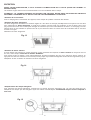
-Entretien des filtres antigraisse:
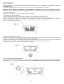
Les filtres antigraisse nécessitent un entretien régulier et il faut donc les nettoyer périodiquement en moyenne tous les deux
mois. Démontez les filtres antigraisse: à l’aide de la poignée, pousser l’arrêt vers l’intérieur et tirer les filtres vers le bas
(Fig.13).Lavez-les avec avec un nettoyant ménager du commerce puis rincer abondamment et sécher. Ce nettoyage peut etre
effectué dans un lave-vaisselle en prenant soin de ne pas mettre les filtres en contact avec de la vaisselle sale ou avec des
couverts en argent.
Remontez les filtres antigraisse.
-Entretien du filtre à charbon:
Si vous utilisez votre appareil en version récyclage, il sera nécessaire de remplacer le filtre à charbon en moyenne tous les
six mois, selon l’emploi. Code filtre à charbon: AH4063U1.
Pour enlever le filtre à charbon, il faut d’abord demonter les filtres antigraisse (Fig.13). Puis, enlevez le filtre à charbon, en
appuyant sur l’arrêt vers l’intérieur et en le faisant pivoter jusqu’à ce que les deux languettes sortent de leurs logements (Fig.14).
Remplacez le filtre à charbon et rémontez les filtres antigraisse.
-Remplacement des lampes halogènes:
Pour remplacer les lampes halogènes, commencez par enlever les filtres antigraisse (Fig. 13). Otez les hublot (Fig.15).
Remplacez les lampes par des halogènes ayant les mêmes caractéristiques. ATTENTION: Ne pas toucher l'ampoule à
main nue.
Fig. 13
Fig. 14
Fig. 15

9
IMPORTANT; BEFORE ANY OPERATION OF INSTALLATION AND USE, TAKE NOTE OF THE
FOLLOWING INSTRUCTIONS:
The distance between the supporting surface for the cooking vessels on the hob and the lower part of the hood must be at least 65
cm. If the instructions for installation for the hob specify a greater distance, this has to be taken into account.
The air collected must not be conveyed into a duct used to blow off smokes from appliances fed with an energy other than electricity
(central heating systems, thermosiphons, water-heaters, etc.).
Comply with the official instructions provided by the competent authorities in merit when installing the disposal duct. In addition,
exhaust air should not be discharged into a wall cavity, unless the cavity is designed for that purpose.
The room must be well aerated in case a hood and some other heat equipment fed with an energy other than electricity (gas, oil,
coal heaters, etc) operate at the same time.
In fact the intake hood, disposing of air, could create a vacuum in the room. The vacuum should not exceed 0,04mbar. This prevents
the gas exhausted by the heat source from being intaken again. It is therefore advisable to ensure the room contains air taps able
to ensure a steady flow of fresh air.
Check the data label inside the appliance; if the symbol (
) is printed, read the following: this appliance has such technical
particulars that it belongs to class II insulation, therefore it must not be earthed.
The following warning is valid in the United Kingdom only: in case your cable is not furnished with a plug, read the following
instructions; as the colours of the wires in the mains lead of this appliance may not correspond with the coloured markings identifying
the terminals in your plug, proceed as follows: – the wire which is coloured blue must be connected to the terminal which is marked
with the letter N or coloured black; – the wire which is coloured brown must be connected to the terminal which is marked with the
letter L or coloured red. – terminal of a three-pin plug.
Check the data label inside the appliance; if the symbol (
) is NOT printed, read the following: ATTENTION: This appliance must
be earthed. When making the electrical connections, check that the current socket has a ground connection.
The following warning is valid in the United Kingdom only: in case your cable is not furnished with a plug, read the following
instructions; as the colours of the wires in the mains lead of this appliance may not correspond with the coloured markings identifying
the terminals in your plug, proceed as follows: – the wire which is coloured green and yellow must be connected to the terminal in
the plug which is marked with the letter E or by the earth symbol [
], or coloured green or green and yellow; – the wire which is
coloured blue must be connected to the terminal which is marked with the letter N or coloured black; – the wire which is coloured
brown must be connected to the terminal which is marked with the letter L or coloured red.
When making the electrical connections, check that the voltage values correspond to those indicated on the data plate inside the
appliance itself. In case your appliance is not furnished with a non separating flexible cable and has no plug, or has not got any other
device ensuring omnipolar disconnection from the electricity main, with a contact opening distance of at least 3 mm, such separating
device ensuring disconnection from the main must be included in the fixed installation. If your unit features a power lead and plug,
position this so the plug is accessible.
Always switch off the electricity supply before carrying out any cleaning or servicing operations on the appliance.
ATTENTION: This appliance must be grounded.
USE
Avoid using materials which could cause spurts of flame (flambées) near the appliance.
When frying, take particular care to prevent oil and grease from catching fire. Already used oil is especially dangerous in this respect.
Do not use uncovered electric grates.
To avoid possible risks of fire always comply with the indicated instructions when cleaning anti-grease filters and when removing
grease deposits from the appliance.
MAINTENANCE
Thorough servicing guarantees correct and long-lasting operation.
Any fat deposits should be removed from the appliance periodically depending on amount of use (at least every 2 months). Avoid
using abrasive or corrosive products. To clean painted appliances on the outside, use a cloth dipped in lukewarm water and neutral
detergent. To clean steel, copper or brass appliances on the outside, it is always best to use specific products, following the
instructions on the products themselves. To clean the inside of the appliance, use a cloth (or brush) dipped in denatured ethyl
alcohol.
ENGLISH

10
Fig. 5
DESCRIPTION OF THE APPLIANCE
The description and characteristics shown in this document are for information only and not obligatory. Indeed, we reserve the
right to carry out any modification or improvement of the quality of certain of our products without prior notice.
Depending on the model purchased, the hoods may be installed in the filtering, ducting or external motor version.
Models: DHG556XP-DHG576XP-DHG577XP-DHG589: These models can be installed both in filtering or ducting versions, in
accordance with your requirements.
In the Filtering version (Fig. 1), the air and vapours conveyed by the appliance are depurated by charcoal filter and recirculated
around the room. ATTENTION: Using the hood as a filtering one it is necessary to use the charcoal filter that purifies the air
sent back into the room.
In the Ducting version (Fig. 2), cooking vapours and odours are conveyed straight outside by a disposal duct which passes
through the wall/ceiling. Use of charcoal filter is therefore unnecessary.
Models DHG560XP-DHG570XP: these models may only be installed in the External motor version (Fig. 3); more particularly
the apparatus must be connected to a ducted control unit that operates remotely, utilising the apparatus as a collection base
for the expelled air.
This apparatus conforms to the 16.08.89 regulation relating to the limitation of radio-electric disturbances (EC Directive n./
6.889 modified by the EC Directive 8/.308.).
INSTALLATION
It is advisable to entrust the installation operations to specialised personnel.
Read carefully the indications in the paragraph “IMPORTANT” at page 9 of the instruction booklet.
To facilitate installation, before starting remove the grease filters: press inward on the clamp at the handle and pull the filter
downward (Fig. 4).
Cut a hole in the bottom of the pensile cupboard in order to settle the appliance (Fig. 5).
The pensile cupboard bottom must be
16 mm thick.
Check that the fixing tabs (Fig. 6) to the wall unit are positioned at a height suited to the thickness of the bottom of the wall
unit. If this distance is less than the thickness, increase it by unscrewing the 2 corresponding screws inside the hood.
INSTALLATION IN FILTERING VERSION
Install the wiring system. Insert the appliance in the hole (Fig. 5). Make the air
evacuation hole on the top of the pensile cupboard (Fig.1). Tighten the 2 screws
inside the appliance (Fig. 7) until it fits snug on the bottom of the wall unit.
Do not tighten the two screws strongly to maintain the two metallic clamps
in the right position. Connect the tube with the device air outlet, to such a height
to reach the top of the pensile cupboard ( the tube is not included).Install again the
grease filters. Make the electrical connection of the hood by means of the power supply cable.
THICKNESS 16mm
Fig. 1
Fig. 2
Fig. 4
MODELS A
DHG556XP
DHG576XP
DHG589XP
DHG560XP
DHG577XP
DHG570XP
690mm
490mm
Fig. 6
Fig. 3

11
INSTALLATION OF THE DUCTING AND EXTERNAL MOTOR VERSIONS
Install the wiring system and prepare the air venting hole (Fig. 2).
Insert the appliance in the hole (Fig. 5).
Tighten the 2 screws inside the appliance (Fig. 7) until it fits snug on the bottom of the wall unit. Do not tighten the two screws
strongly to maintain the two metallic clamps in the right position.
To get optimal conditions the air venting pipe should: be as short as possible, have the lowest number of bends (max bende angle:
90°), be made of material approved by local authorities (according to the State), have its inner side as regular and smooth as
possible. It is moreover recommended to avoid drastic changes of pipe cross section (recommended diameter: 150 mm). The
device is provided with a 150-125 cm reduction.
Connect the air exit tube with the device air outlet (Fig. 2): use a flexible tube and stop it in the device air outlet through a metallic
clamp (tube and clamp are not provided).
Remove the charcoal filter by placing pressure on the clamp located on the interior of the hood and rotating it until the two tabs
are removed from position (Fig. 8).
Rimontare i filtri antigrasso.
Make the electrical connection of the hood by means of the power supply cable.
Only for those models with the external motor (DHG560XP-DHG570XP): Connect the electrical wires of the hood to the external
motor via the relevant terminals (Fig. 9); remove cable fastener A to the cover B of the connection box. Fix the external motor’s
power supply cable to the C terminal. Reassemble the cable fastener A and the cover B of the connection box. The other
extremity of the cable is to be fixed to the terminal of the external motor.
DEVICE DISASSEMBLY
Remove the grease filter .
During the following operations always support the device.
Tighten the 2 screws inside the device (Fig. 7); moving
the 2 small tongues toward the device inside using the
right carvings (Fig. 10); pull out the device from its side.
A
C
B
Fig. 7
Fig. 8
Fig. 9
Fig. 10

12
FUNCTIONING OF THE APPARATUS
Depending on the model, the unit is equipped with the following controls:
DHG556XP, DHG576XP, DHG577XP, DHG560XP, DHG570XP
CONTROLS - Fig. 11:
A) ON/OFF - lamps. This button is also used for the alarm function of the grease and charcoal filters.
Filter alarm: After 30h of motor operation, the L1 LED comes ON and remains ON (the grease filters have to be cleaned). After
120h of motor operation, the L1 LED comes ON and flashes (the charcoal filter have to be changed if the hood is so equipped).
The Filter Alarm is ONLY given with the motor is OFF. The Filter Alarm is cancelled (HOUR meter reset) by holding down button
A for 2". B) Press button B to start the motor at Speed 1. The speed is shown by the L2 LED coming ON. When held down
for 2", the motor switches off. A single pressure on the button when the LED is ON activates the timer function (motor ON for
5'), shown by the flashing LED. To cancel the timer function, press the button again ONCE. C) Press button C to start the motor
at Speed 2. The speed is shown by the L3 LED coming ON. A single pressure on the button when the led is on activates the
timer function (motor on for 5'), shown by the flashing led. To cancel the timer function, press the button again ONCE. D) Press
button D to start the motor at Speed 3. The speed is shown by the L4 LED coming ON. A single pressure on the button when
the led is on activates the timer function (motor on for 5'), shown by the flashing led. To cancel the timer function, press the
button again ONCE. E) Press button E to start the il motor at Speed 4. The speed is shown by the L5 LED coming ON. A single
pressure on the button when the led is on activates the timer function (motor on for 5'), shown by the flashing led. To cancel
the timer function, press the button again ONCE.
ATTENTION : BY ACTIVATING THE
TIMER FUNCTION, THE MOTOR SWITCHES OFF AFTER 5 MINUTES.
ATTENTION : WHEN THE
LED L1 LIGHTS UP IT IS TIME TO CLEAN THE GREASE FILTERS OR REPLACE THE
CHARCOAL FILTER.
DHG589XP
CONTROLS - Fig. 12:
A) ON/OFF - lamps. This button is also used for the alarm function of the grease and charcoal filters.
Filter alarm: After 30h of motor operation, the L1 LED comes ON and remains ON for 30" (the grease filters have to be cleaned).
After 120h of motor operation, the L1 LED comes ON and flashes for 30" (the charcoal filter have to be changed if the hood
is so equipped). The Filter Alarm is ONLY given with the motor is OFF. The Filter Alarm is cancelled (HOUR meter reset) by
holding down button A for 2".
B) The button B activates/deactivate sensor function (when activated the sensor is lit by the LED L2).
C) Press button C to start the motor at Speed 1. The speed is shown by the L3 LED coming ON. When held down for 2", the
motor switches off.
D) Press button D to start the motor at Speed 2. The speed is shown by the L4 LED coming ON.
E) Press button E to start the motor at Speed 3. The speed is shown by the L5 LED coming ON.
F) Press button F to start the il motor at Speed 4. The speed is shown by the L6 LED coming ON.
SENSOR SENSITIVITY: sensitivity of the sensor may be modified in accordance with individual requirements. Modify the
sensitivity by pressing simultaneously on the A and B buttons. The set sensitivity level will be displayed via the 4 flashing Leds
- L3, L4, L5, and L6. The desired sensitivity is set via the C, D, E, and F buttons (C being minimum, F being maximum). Set
the sensitivity level to minimum for gas cook tops, medium for glass-ceramic cook tops and maximum for induction cook tops.
WARNING: WHEN
LED L1 LIGHTS UP, THIS INDICATES THAT THE GREASE OR CHARCOAL FILTERS REQUIRE
CLEANING.
FILTER SENSOR (activated via the B button): this device is equipped with a completely automatic system (Advanced Sensor
Control) for management of all hood functions. Thanks to the Advanced sensor Control (ASC), air circulating in the kitchen is
maintained clean and odour-free without requiring any user intervention. The sophisticated sensors are able to capture any type
of odour, vapour, smoke or heat caused by cooking. The ASC also captures any possible irregular gases present in the
environment.
When the sensor function is activated, the C, D, E and F buttons activate the speed temporarily, to then be overridden by the
automatic speed setting.
Fig. 11
Fig. 12

13
Technical data - DHG556XP:
- 1 Motor - power 155W
- Voltage: 230-240V single phase
- 2 halogen lamps 20W
- Supplied with 150 cm electricity supply cable with plug.
- Gross weight: Kg.11
- Net weight: Kg.8,5
- 2 metallic grease filters
Technical data - DHG576XP:
- 1 Motor - power 250W
- Voltage: 230-240V single phase
- 2 halogen lamps 20W
- Supplied with 150 cm electricity supply cable with plug.
- Gross weight: Kg.11
- Net weight: Kg.8,5
- 2 metallic grease filters
Technical data - DHG577XP:
- 1 Motor - power 250W
- Voltage: 230-240V single phase
- 2 halogen lamps 20W
- Supplied with 150 cm electricity supply cable with plug.
- Gross weight: Kg.13,5
- Net weight: Kg.10
- 2 metallic grease filters
Dimensions
Technical data - DHG589XP:
- 1 Motor - power 350W
- Voltage: 230-240V single phase
- 2 halogen lamps 20W
- Supplied with 150 cm electricity supply cable with plug.
- Gross weight: Kg.12
- Net weight: Kg.9,5
- 2 metallic grease filters
Technical data - DHG560XP:
- Voltage: 230-240V single phase
- 2 halogen lamps 20W
- Supplied with 150 cm electricity supply cable with plug.
- Gross weight: Kg. 8
- Net weight: Kg. 6
- 2 metallic grease filters
Technical data - DHG570XP:
- Voltage: 230-240V single phase
- 2 halogen lamps 20W
- Supplied with 150 cm electricity supply cable with plug.
- Gross weight: Kg. 10,5
- Net weight: Kg. 8,5
- 2 metallic grease filters
ELECTRICITY CONNECTION
While connecting the electricity make sure that the tension is that indicated in the technical lable.
Before proceeding to cleaning or maintenance operations remove the tension.
Connecting the electricity must be performed by a specialised technician in conformity with the regulation in force.
This apparatus is constructed so as to belong to the I insulation class and therefore needs grounding.
DHG560XP
DHG556XP
DHG576XP
DHG589XP
DHG577XP
DHG570XP

14
MAINTENANCE
REMOVE THE TENSION AT THE HOOD (PLUG or SWITCH) BEFORE ANY OPERATION-
Thorough servicing guarantees correct and long-lasting operation.
WARNING: MODEL DHG589XP HAS THIS SENSOR. AVOID USING SILICON BASED PRODUCTS IN THE VICINITY OF
THE HOOD TO PREVENT SENSOR DAMAGE.
-Maintenance of the casing:
Avoid products containing abrasives when cleaning the casing.
-Maintenance of the grease filters:
The grease filters require regular maintenance and must be cleaned periodically every two months.
Remove the grease filters in correspondence with the handle, push the stop inward and pull the filter downwards (Fig.13). Wash
them with a normal neutral product in commerce, then rinse abundantly and dry. The washing can be carried out in the
dishwasher making sure not to let the filters make contact with dirty or silver dishes.
Remount the grease filters.
-Maintenance of the charcoal filter:
If you are using the filtering version apparatus, the charcoal filter need to be changed every six months on average depending
on the use made of the hood. Reference charcoal filter: AH4063U1.
To take away the charcoal filter, firstly you must remove the grease filters (Fig.13). Following this, remove the charcoal filter
by placing pressure on the clamp located on the interior of the hood and rotating it until the two tabs are removed from position
(Fig. 14). Replace the charcooal filter and install again the grease filters.
-Changing the halogen lamps:
To replace the halogen bulbs, remove the grease filters (Fig. 13). Open the cover levering from the proper slots (Fig.15).
Change with a lamp of the same kind. CAUTION: Do not handle glass bulb with bare hands.
Fig. 13
Fig. 14
Fig. 15

15
WICHTIG: VOR DEM AUSFÜHREN VON INSTALLATIONSSCHRITTEN UND DER INBETRIEBNAHME,
DIE FOLGENDEN ANWEISUNGEN LESEN:
Der Mindestabstand zwischen der Topf-Trägerfläche auf der Kochmulde und dem unteren Teil der Abzughaube muss 65 cm
betragen. Geben die Installationsanleitungen der Kochmulde einen höheren Abstand an, so ist dieser einzuhalten.
Ein Anschluss der Abluftleitungen an Verbrennung-sabgaskamine (zum Beispiel Zentralheizung, Heizgeräte, Badezimmeröfen
usw.) ist nicht gestattet.
In jedem Fall sind bei der Ableitung der Abluft die behördlichen Vorschriften zu beachten. Desweiteren darf die Abluft nur dann
durch ein Loch in der Wand geleitet werden, wenn dieses für diesen Zweck bestimmt ist.
Achtung! Bei gleichzeitigem Betrieb einer Abluft-Dunstabzugshaube und einer raumluftabhängigen Feuerstätte (wie z. B. gas-
, öl- oder kohlebetriebene Heizgeräte, Durchlauferhitzer, Warmwasserbereiter) ist Vorsicht geboten, da beim Absaugen der Luft
durch die Dunstabzugshaube dem Aufstellraum die Luft entnommen wird, die die Feuerstätte zur Verbrennung benötigt. Ein
gefahrloser Betrieb ist möglich, wenn bei gleichzeitigem Betrieb von Haube und raumluftabhängiger Feuerstätte im Aufstellraum
der Feuerstätte ein Unterdruck von höchstens 0,04 mbar erreicht wird und damit ein Rücksaugen der Feuerstättenabgase
vermieden wird. Daher den Raum mit Lüftungsanschlüssen versehen, die einen konstanten Zustrom von Frischluft gewährleisten.
Das Typenschild im Innern des Geräts kontrollieren: Den folgenden Anweisungen folgen, falls das Symbol (
) erscheint; dieses
Gerät weist konstruktive technische Details auf, die unter die Isolierungsklasse II fallen und deshalb muss es nicht geerdet
werden.
Das Typenschild im Innern des Geräts kontrollieren: den folgenden Anweisungen folgen, falls das Symbol (
) NICHT erscheint;
ACHTUNG: dieses Gerät muss geerdet werden. Beim elektrischen Anschluss sicherstellen, dass die Steckdose eine Erdung
aufweist.
Beim elektrischen Anschluss muss überprüft werden, ob die Spannungswerte des Stromnetzes mit den Werten auf dem im Innern
des Gerätes angebrachten Typenschilds übereinstimmen. Falls Ihr Gerät nicht mit einem fest angeschlossenem Kabel mit
Stecker oder einer sonstigen Vorrichtung, die eine allpolige Unterbrechung mit einer Kontaktöffnung von mindestens 3 mm
versehen ist, so müssen die entsprechenden Trennvorrichtungen bei der festen Installation vorgesehen werden. Das Gerät so
aufstellen, dass der Stecker zugänglich ist, falls Ihr Gerät mit einem Netzkabel mit Stecker ausgestattet ist.
Vor jeder Reinigungs- oder Wartungsarbeit muss das Gerät vom Stromnetz getrennt werden.
ACHTUNG: dieses Gerät muss geerdet werden.
GEBRAUCH
In der unmittelbaren Nähe des Geräts die Benutzung von flammenerzeugenden Materialien (Flambieren) vermeiden.
Beim Frittieren besonders auf die Brandgefahr achten, die durch Öl und Fette verursacht wird. Besonders gefährlich ist die
Entflammbarkeit von bereits benutztem Öl. Keine offenen Elektrogrills verwenden.
Zur Vermeidung einer möglichen Brandgefahr die Anweisungen zur Reinigung der Fettfilter und zur Entfernung eventueller
Fettablagerungen auf dem Gerät beachten.
WARTUNG
Nur eine sorgfältige Pflege garantiert auf Dauer eine gute Leistung und Funktion des Geräts.
Die Entfernung eventueller Fettablagerungen vom Gerät erfolgt in regelmäßigen Abständen in Abhängigkeit von der Benutzung
(zumindest alle zwei Monate). Die Verwendung von scheuernden oder korrosiven Produkten vermeiden. Für die äußere Reinigung
von lackierten Geräten ein mit lauwarmen Wasser und Neutralreiniger angefeuchtetes Tuch verwenden; für die äußere Reinigung
der Geräte aus Stahl, Kupfer und Messing wird die Verwendung von Spezial-produkten empfohlen, wobei die auf dem Produkte
angegebenen Anweisungen zu beachten sind; für die innere Reinigung der Geräte einen in denaturalisierten Äthylalkohol
eingetauchten Lappen (oder Pinsel) verwenden.
DEUTSCH

16
GERÄTEBESCHREIBUNG
Die im vorliegenden Dokument erwähnten Beschreibungen und Eigenschaften dienen Informationszwecken und sind nicht Pflicht.
Der Qualität unserer Produkte sicher, behalten wir uns das Recht vor, ohne Vorankündigung beliebige Änderungen bzw.
Verbesserungen vorzunehmen.
Je nach dem erstandenen Modell kann die Haube mit Umluft- oder Abluftversion oder mit einem Außenmotor installiert werden.
Modelle DHG556XP- DHG576XP- DHG577XP-DHG589: Diese Modelle können je nach Bedarf mit Filter- oder Saugfunktion
installiert werden.
Bei Umluftversion (Abb. 1) werden die durch das Gerät beförderten Dünste und die Abluft durch der Kohlefilter gereinigt und
wieder in den Raum zurückgeführt. ACHTUNG: Bei Umluftversion sind Kohlefilter zu verwenden, die die in den Raum
zurückgeführte Luft reinigen.
Bei Abluftversion (Abb. 2) werden Dampf und Küchengerüche direkt, mit einem durch Wand oder Zimmerdecke geführten
Abluftkanal, ins Freie geleitet. Deshalb fällt der Gebrauch von Kohlefiltern in diesem Falle weg.
Modelle DHG560XP-DHG570XP: Diese Modelle können nur als Ausführungen mit äußerem Motor installiert werden (Abb. 3).
Das bedeutet, dass das Gerät an eine Saugsteuerung angeschlossen werden muss, die von einem getrennten Ort aus arbeitet
und welche das Gerät als eine Zuleitungsbasis für die abzuleitende Luft benutzt.
Dieses Gerät entspricht der Gesetzesbestimmung vom 16.08.89 bezüglich der Beschränkung von Funkstörungen (EWG-
Richtlinie Nr.76.889 abgeändert von der EWG-Richtlinie 87.308.)
INSTALLATION
Es wird empfohlen, die Installationsschritte von einem Fachmann ausführen zu lassen.
Bitte genau die Hinweise des Paragraphen „WICHTIG“ auf Seite 15 der Bedienungsanleitung lesen. Vor den
Montageoperationen muß/müssen zur leichteren Handhabung des Geräts die Antifettfilter entfernt werden: Den Festhalter
in der Nähe des Griffs nach innen drücken und den Filter nach unten ziehen (Abb. 4).
Vor der Montage des Geräts muß in der Hängeschrankunterseite ein dem Gerät entsprechender Ausschnitt vorgenommen
werden (Abb.5).
Die Hängeschrankunterseite muss 16 mm dick sein.
Überprüfen, dass die Befestigungsflügel (Abb. 6) zum Festmachen am Hängeschranks in einer angemessenen Höhe im
Verhältnis zur Dicke des Hängeschrankbodens positioniert sind.
Sollte dieser Abstand geringer sein als die Dicke, muss er erhöht werden,
indem die beiden hierfür vorgesehenen Schrauben im Innern des Geräts gelockert werden.
INSTALLATION UMLUFTVERSION
Außerdem ist für einen Stromanschluß zu sorgen.
Das Gerät in den Ausschnitt eingefügen (Abb. 5).
Ein Luftabzugsloch oberhalb des Hängeschrankes vorbereiten. (Abb.1)
Die im Gerät 2 Schrauben anziehen (Abb. 7) bis das Teil auf der Hinterseite des
Hänßeschranks haftet. Die beiden Schrauben nicht forcieren, damit die Metallbügel in
der richtigen Position bleiben. Einen Schlauch (nicht mitgeliefert) am Luftausgang des Gerätes
bis oberhalb des Hängeschranks anschließen. Die Fettfilter wieder montieren. Nun kann das
Gerät an die Stromversorgung angeschlossen werden.
STÄRKE 16mm
Abb. 1
Abb. 2
Abb. 4
Abb. 5
MODELS A
DHG556XP
DHG576XP
DHG589XP
DHG560XP
DHG577XP
DHG570XP
690mm
490mm
Abb. 6
Abb. 3

17
INSTALLATION MIT ABLUFTVERSION UND AUSSENMOTOR
Für die Stromzufuhr sorgen und eine Öffnung zur Luftableitung vorsehen (Abb. 2).
Das Gerät in den Ausschnitt eingefügen (Abb. 5).
Die im Gerät 2 Schrauben anziehen (Abb. 7) bis das Teil auf der Hinterseite des Hänßeschranks haftet. Die beiden
Schrauben nicht forcieren, damit die Metallbügel in der richtigen Position bleiben.
Um die bestmöglichsten Vorbedingungen zu erreichen, ist es zu empfehlen Abluftrohre mit folgenden Eigenschaften zu
verwenden: möglichst kurzgehaltene Länge und, die geringste Anzahl von Kurven (Maximalwinkel der Kurve= 90 Grad), es
müssen normengerechte (je nach Staat) Materialien verwendet werden, Innenseite möglichst glatt. Ausserdem ist es ratsam,
drastische Veränderungen des Rohrquerschmittes zu vermeiden (empfohlener Durchmesser: 150 mm). Das Gerät ist mit einem
Reduzierstück 150-125cm ausgestattet.
Den Luftabzugsschlauch am Luftausgang des Gerätes (Abb.2) anschließen. Dazu einen flexiblen Schlauch verwenden, der mit
einer Metallklemme am Luftausgang des Gerätes fixiert wird. (Schlauch und Klemme werden nicht mitgeliefert).
Zur Abnahme des Kohlefilters den Haltestift nach innen drücken und so lange drehen, bis die beiden Laschen zum Vorschein
kommen (Abb.8).
Die Fettfilter wieder montieren.
Nun kann das Gerät an die Stromversorgung angeschlossen werden.
Nur für Modelle mit Außenmotor (DHG560XP- DHG570XP): Die Haube mit den entsprechenden Klemmen an den Strom der
außenliegenden Steuerung anschließen (Abb.9): Kabelklemme A und Deckel B aus dem Anschlusskasten nehmen.
Verbindungskabel der Steuerung in der Klemme C anbringen. Kabelklemme A und Deckel B des Anschlusskastens wieder
befestigen. Das andere Kabelende muss an der Klemme der außenliegenden Steuerung angeschlossen werden.
ABMONTIEREN DES GERÄTES
Den/die Fettfilter entfernen.
Während der folgenden Arbeiten immer das Gerät abstützen.
Die zwei Schrauben im Geräteinneren (Abb.7) lockern, die
beiden Zungen in Richtung Geräteinneres über die
vorgesehenen Einschnitte verschieben (Abb.10) und das
Gerät herausnehmen.
A
C
B
Abb. 7
Abb. 8
Abb. 9
Abb. 10

18
FUNKTIONSWEISE DES GERÄTES
Je nach Version ist das Gerät mit folgenden Bedienung ausgestattet:
DHG556XP, DHG576XP, DHG577XP, DHG560XP, DHG570XP
Bedienung - Abb. 11:
A) Lampen EIN/AUS. Diese Taste wird auch für die Fett- und Kohlenfilter-Alarmfunktion verwendet
Filteralarm: Nach 30 Motorbetriebsstunden schaltet sich die LED L1 ein und bleibt eingeschaltet (es ist Zeit, die Fettfilter zu
reinigen). Nach 120 Motorbetriebsstunden schaltet sich die LED L1 ein und blinkt (es ist Zeit, die Kohlenfilter auszutauschen,
falls die Haube hiermit ausgestattet ist). Der Filteralarm wird NUR bei STEHENDEM Motor angezeigt. Zur Rückstellung des
Filteralarms (Rückstellung des STUNDEN-Zählers) ist die Taste A 2 Sekunden lang gedrückt zu halten. B) Bei Drücken der
Taste B schaltet sich der Motor auf der ersten Geschwindigkeitsstufe ein. Die Geschwindigkeit wird von der eingeschalteten
LED L2 angezeigt. Wenn die Taste für 2 Sekunden gedrückt gehalten wird, schaltet sich der Motor aus. Bei einmaligem Drücken
der Taste bei eingeschalteter LED wird die Timerfunktion aktiviert (Motor bleibt 5 Sekunden eingeschaltet), was durch die
blinkende LED angezeigt wird. Zur Aufhebung der Timerfunktion ist die Taste erneut einmal zu drücken. C) Bei Drücken der
Taste C schaltet sich der Motor auf der zweiten Geschwindigkeitsstufe ein. Die Geschwindigkeit wird von der eingeschalteten
LED L3 angezeigt. Bei einmaligem Drücken der Taste bei eingeschalteter LED wird die Timerfunktion aktiviert (Motor bleibt
5 Sekunden eingeschaltet), was durch die blinkende LED angezeigt wird. Zur Aufhebung der Timerfunktion ist die Taste erneut
einmal zu drücken. D) Bei Drücken der Taste D schaltet sich der Motor auf der dritten Geschwindigkeitsstufe ein. Die
Geschwindigkeit wird von der eingeschalteten LED L4 angezeigt. Bei einmaligem Drücken der Taste bei eingeschalteter LED
wird die Timerfunktion aktiviert (Motor bleibt 5 Sekunden eingeschaltet), was durch die blinkende LED angezeigt wird. Zur
Aufhebung der Timerfunktion ist die Taste erneut einmal zu drücken. E) Bei Drücken der Taste E schaltet sich der Motor auf
der vierten Geschwindigkeitsstufe ein. Die Geschwindigkeit wird von der eingeschalteten LED L5 angezeigt. Bei einmaligem
Drücken der Taste bei eingeschalteter LED wird die Timerfunktion aktiviert (Motor bleibt 5 Sekunden eingeschaltet), was durch
die blinkende LED angezeigt wird. Zur Aufhebung der Timerfunktion ist die Taste erneut einmal zu drücken.
ACHTUNG : BEI BETÄTIGUNG DER
TIMERFUNKTION SCHALTET SICH DER MOTOR NACH 5 MINUTEN AUTOMATISCH AUS.
ACHTUNG : LEUCHTET DIE
LED L1 AUF, SOLLTEN DI FETTFILTER GEREINIGT ODER DIE KOHLENFILTER
AUSGEWECHSELT WERDEN.
DHG589XP
Bedienung - Abb. 12:
A) Lampen EIN/AUS. Diese Taste wird auch für die Fett- und Kohlenfilter-Alarmfunktion verwendet
Filteralarm: Nach 30 Motorbetriebsstunden schaltet sich die LED L1 ein und bleibt 30 Sekunden lang eingeschaltet (es ist
Zeit, die Fettfilter zu reinigen). Nach 120 Motorbetriebsstunden schaltet sich die LED L1 ein und blinkt für 30 Sekunden (es
ist Zeit, die Kohlenfilter auszutauschen, falls die Haube hiermit ausgestattet ist). Der Filteralarm wird NUR bei STEHENDEM
Motor angezeigt. Zur Rückstellung des Filteralarms (Rückstellung des STUNDEN-Zählers) ist die Taste A 2 Sekunden lang
gedrückt zu halten.
B) Mit der Taste B wird der Sensor aktiviert/deaktiviert (nach der Aktivierung des Sensors leuchtet Led L2).
C) Bei Drücken der Taste C schaltet sich der Motor auf der ersten Geschwindigkeitsstufe ein. Die Geschwindigkeit wird von
der eingeschalteten LED L3 angezeigt. Wenn die Taste für 2 Sekunden gedrückt gehalten wird, schaltet sich der Motor aus.
D) Bei Drücken der Taste D schaltet sich der Motor auf der zweiten Geschwindigkeitsstufe ein. Die Geschwindigkeit wird von
der eingeschalteten LED L4 angezeigt. E) Bei Drücken der Taste E schaltet sich der Motor auf der dritten Geschwindigkeitsstufe
ein. Die Geschwindigkeit wird von der eingeschalteten LED L5 angezeigt. F) Bei Drücken der Taste F schaltet sich der Motor
auf der vierten Geschwindigkeitsstufe ein. Die Geschwindigkeit wird von der eingeschalteten LED L6 angezeigt.
SENSORENSENSIBILITÄT: Die Sensibilität des Sensors kann je nach Bedarf reguliert werden. Bei gleichzeitigem Drücken
der Tasten A und B wird die eingegebene Sensibilität durch das Blinken der 4 Led L3, L4, L5 und L6 angezeigt. Mit den Tasten
C, D, E und F kann nun die gewünschte Sensibilität eingestellt werden (Taste C Mindestsensibilität, Taste F Höchstsensibilität).
Für die Gaskochfelder die geringste Sensibilitätsstufe, für die Glaskeramikkochfelder die mittlere Sensibilitätsstufe, und für
die Induktionskochfelder die höchste Sensibilitätsstufe einstellen.
ACHTUNG:
LED L1 BLINKT. ENTWEDER KOHLEFEILTER WECHSELN ODER FETTFILTER REINIGEN.
SENSORENFUNKTION (Aktivierung mit Taste B): Dieses Gerät ist mit einem vollautomatischen System (Advanced Sensor
Control) ausgestattet, mit dem alle Funktionen der Haube gesteuert werden. Durch dieses System haben Sie stets saubere
und geruchsfreie Luft in Ihrer Küche, ohne selbst etwas tun zu müssen. Diese sehr sensiblen Sensoren erkennen alle Arten
von Gerüchen, Dampf, Rauch oder Wärme, die beim Kochen entstehen. Das ASC System reagiert sogar auf GAS.
Wenn die Sensorfunktion aktiviert ist, so wird die Geschwindigkeit nur vorübergehend mit den Tasten C, D, E, und F eingestellt,
da der Sensor die Geschwindigkeit dann automatisch reguliert.
Abb. 11
Abb. 12

19
Technische Daten - DHG556XP:
- 1 Motor mit 155W Leistung
- Spannung: 230-240V einphasig
- Beleuchtung durch 2 20W-Halogenlampen
- Mit 150 cm langem Speisekabel zur
Steckdose ausgestattet
- Bruttogewicht: 11 kg
- Nettogewicht: 8,5 kg
- 2 metallische Fettfilter
Technische Daten
- DHG576XP:
- 1 Motor mit 250W Leistung
- Spannung: 230-240V einphasig
- Beleuchtung durch 2 20W-Halogenlampen
- Mit 150 cm langem Speisekabel zur
Steckdose ausgestattet
- Bruttogewicht: 11 kg
- Nettogewicht: 8,5 kg
- 2 metallische Fettfilter
Technische Daten
- DHG577XP:
- 1 Motor mit 250W Leistung
- Spannung: 230-240V einphasig
- Beleuchtung durch 2 20W-Halogenlampen
- Mit 150 cm langem Speisekabel zur
Steckdose ausgestattet
- Bruttogewicht: 13,5 kg
- Nettogewicht: 10 kg
- 2 metallische Fettfilter
Maße
STROMANSCHLUSS
Beim Stromanschluss überprüfen, dass die Spannung der auf dem Typenschild angegebenen entspricht.
Vor Beginn der Reinigungs- und Wartungsschritte das Gerät vom Netz trennen.
Der Stromanschluss muss gemäß den geltenden Bestimmungen vom Fachmann vorgenommen werden.
Dieses Gerät ist so konstruiert, dass es zur Isolationsklasse I gehört; es muss daher geerdet werden.
Technische Daten
- DHG589XP:
- 1 Motor mit 350W Leistung
- Spannung: 230-240V einphasig
- Beleuchtung durch 2 20W-Halogenlampen
- Mit 150 cm langem Speisekabel zur
Steckdose ausgestattet
- Bruttogewicht: 12 kg
- Nettogewicht: 9,5 kg
- 2 metallische Fettfilter
Technische Daten
- DHG560XP:
- Spannung: 230-240V einphasig
- Beleuchtung durch 2 20W-Halogenlampen
- Mit 150 cm langem Speisekabel zur
Steckdose ausgestattet
- Bruttogewicht: 8 kg
- Nettogewicht: 6 kg
- 2 metallische Fettfilter
Technische Daten
- DHG570XP:
- Spannung: 230-240V einphasig
- Beleuchtung durch 2 20W-Halogenlampen
- Mit 150 cm langem Speisekabel zur
Steckdose ausgestattet
- Bruttogewicht: 10,5 kg
- Nettogewicht: 8,5 kg
- 2 metallische Fettfilter
DHG560XP
DHG556XP
DHG576XP
DHG589XP
DHG577XP
DHG570XP

20
WARTUNG
VOR BEGINN DER ARBEITEN STETS DIE HAUBE VOM NETZ TRENNEN (STECKDOSE ODER SCHALTER).
Nur eine sorgfältige Pflege garantiert auf Dauer eine gute Leistung und Funktion des Geräts.
ACHTUNG: DAS MODELL DHG589XP ISST MIT EINEM SENSOR AUSGESTATTET. VERWENDEN SIE KEINE
SILIKONHALTIGEN PRODUKTE IN UNMITTELBERER NÄHE, UM SCHÄDEN AM SENSOR ZU VERMEIDEN.
- Wartung des Gehäuses:
Bei der Säuberung des Gehäuses ist die Verwendung von Produkten, die Scheuermittel enthalten, zu vermeiden.
- Wartung des Fettfilters
Die Fettfilter benötigen eine regelmäßige Wartung und müssen alle zwei Monate gereinigt werden. Die Fettfilter entfernen:
Entsprechend dem Griff die Sperre nach innen drücken und den Filter nach unten ziehen (Abb.13). Die Filter mit einem normalen
im Handel erhältlichen neutralen Produkt waschen, anschließend reichlich spülen und trocknen. Die Waschung kann auch in der
Geschirrspülmaschine vorgenommen werden, dabei ist darauf zu achten, die Filter nicht mit schmutzigem oder silbernem
Geschirr in Berührung kommen zu lassen. Die Fettfilter wieder einbauen.
- Wartung der Kohlefilter:
Wenn Sie das Gerät im Umluftbetrieb benutzen, müssen der Kohlefilter je nach Gebrauch im Durchschnitt alle sechs Monate
ausgewechselt werden. Referenzdaten Kohlefilter: AH4063U1.
Zur Entfernung der Kohlefilter müssen zunächst die Fettfilter (Abb.13) entfernt werden.
Nehmen Sie dann den Kohlefilter an, indem Sie den Haltestift nach innen drücken und so lange drehen, bis die beiden Laschen
zum Vorschein kommen (Abb.14).
Der Kohlefilter austauschen und die Fettfilter wieder montieren.
- Auswechselung der Halogenlampen:
Zum Wechsel der Halogenlampen müssen zunächst die Fettfilter abgenommen werden (Abb. 13). Fassen Sie den Deckel an
den entsprechenden Vertiefungen und nehmen Sie den Deckel ab (Abb. 15).
Mit Lampen desselben Typs ersetzen.
ACHTUNG:
Glaskolben nicht mit bloßen Händen anfassen.
Abb. 13
Abb. 14
Abb. 15
Seite wird geladen ...
Seite wird geladen ...
Seite wird geladen ...
Seite wird geladen ...
Seite wird geladen ...
Seite wird geladen ...
Seite wird geladen ...
Seite wird geladen ...
Seite wird geladen ...
Seite wird geladen ...
Seite wird geladen ...
Seite wird geladen ...
Seite wird geladen ...
Seite wird geladen ...
Seite wird geladen ...
Seite wird geladen ...
Seite wird geladen ...
Seite wird geladen ...
Seite wird geladen ...
Seite wird geladen ...
Seite wird geladen ...
Seite wird geladen ...
Seite wird geladen ...
Seite wird geladen ...
Seite wird geladen ...
Seite wird geladen ...
Seite wird geladen ...
Seite wird geladen ...
-
 1
1
-
 2
2
-
 3
3
-
 4
4
-
 5
5
-
 6
6
-
 7
7
-
 8
8
-
 9
9
-
 10
10
-
 11
11
-
 12
12
-
 13
13
-
 14
14
-
 15
15
-
 16
16
-
 17
17
-
 18
18
-
 19
19
-
 20
20
-
 21
21
-
 22
22
-
 23
23
-
 24
24
-
 25
25
-
 26
26
-
 27
27
-
 28
28
-
 29
29
-
 30
30
-
 31
31
-
 32
32
-
 33
33
-
 34
34
-
 35
35
-
 36
36
-
 37
37
-
 38
38
-
 39
39
-
 40
40
-
 41
41
-
 42
42
-
 43
43
-
 44
44
-
 45
45
-
 46
46
-
 47
47
-
 48
48


De Dietrich DHG556XP Bedienungsanleitung
- Kategorie
- Dunstabzugshauben
- Typ
- Bedienungsanleitung
in anderen Sprachen
- English: De Dietrich DHG556XP Owner's manual
- français: De Dietrich DHG556XP Le manuel du propriétaire
- español: De Dietrich DHG556XP El manual del propietario
- italiano: De Dietrich DHG556XP Manuale del proprietario
- Nederlands: De Dietrich DHG556XP de handleiding
- português: De Dietrich DHG556XP Manual do proprietário