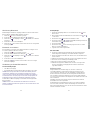
Radiodetection RD7000 Plus Benutzerhandbuch
- Typ
- Benutzerhandbuch

RD7000+
™
Universal precision electromagnetic
and RF marker locator
User Guide
Kurzbedienungsanleitung
90/UG095INT/02

ENGLISH 4
DEUTSCH 28

ENGLISH
4 5
Preface
About this guide
CAUTION: This guide provides basic operating instructions for the
RD7000+ locator and transmitter. It also contains important safety
information and guidelines and as such should be read in its entirety
before attempting to operate the RD7000+ Locator and transmitter.
This guide is intended as a quick reference guide only. For detailed instructions, including
the use of accessories, help with eCert
™
, CALSafe
™
*, SurveyCERT
™
and automatic
logging* please refer to the RD7000+ locator operation, SurveyCERT and RD Manager
™
manuals, which are available for download from www.radiodetection.com.
The online User Manual library also contains links to the SurveyCERT and
RD Manager manuals.
*Logging models only.
WARNING! Direct connection to live conductors is POTENTIALLY LETHAL.
Direct connections to live conductors should be attempted by fully qualified
personnel only using the relevant products that allow connections to energized
lines.
WARNING! The transmitter is capable of outputting potentially lethal
voltages. Take care when applying signals to any pipe or cable and be sure to
notify other technicians who may be working on the line.
WARNING! Reduce audio level before using headphones to avoid damaging
your hearing.
WARNING! This equipment is NOT approved for use in areas where
hazardous gases may be present.
WARNING! When using the transmitter, switch off the unit and disconnect
cables before removing the battery pack.
WARNING! The RD7000+ locator will detect most buried conductors but
there are some objects that do not radiate any detectable signal. The RD7000+,
or any other electromagnetic locator, cannot detect these objects so proceed
with caution. There are also some live cables which the RD7000+ will not be
able to detect in Power mode. The RD7000+ does not indicate whether a signal
is from a single cable or from several in close proximity.
WARNING! Batteries can get hot after prolonged use at full output power.
Take care while replacing or handling batteries.
Extended Warranty
Thank you for purchasing the RD7000+ locator and transmitter.
RD7000+ locators and transmitters are covered by a 1 year warranty as standard.
Customers can extend this warranty to a total of 3 years by registering the
products within 3 months of purchase.
Registration is carried out using the RD Manager PC software which can be
downloaded from the Radiodetection website. Visit www.radiodetection.com/
RDManager.
From time to time Radiodetection may release new software to improve the
performance or add new functionalities to these products. By registering, users
will benefit from subscribing to email alerts advising about any new software and
special offers related to its product range.
Users will be able to opt out at any moment from receiving software or technical
notifications as well as from receiving marketing material.
eCert
The RD7000+ locator is safety equipment which should be regularly checked to
ensure its correct operation.
eCert provides a thorough test of the RD7000+’s locating circuitry and marker
transceiver, and supplies a Radiodetection Calibration Certificate when a positive
test result is obtained.
To run eCert, the locator should be connected to an internet-enabled PC
on which the RD Manager software is installed. Additional purchase may be
required.
Refer to the RD Manager operation manual for further details.

ENGLISH
6 7
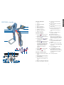
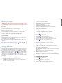
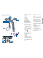
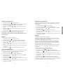
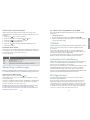
RD7000+ locator
Locator features
1. Keypad
2. LCD with auto backlight
3. Speaker
4. Battery compartment
5. Battery charger connector
6. Accessory connector
7. Headphone connector
8. Bluetooth
®
module antenna
9. Marker loop antenna
Locator keypad
10. Power key : Switches the unit on
and off. Opens the locator menu.
11. Frequency key
: Selects frequency.
Closes submenu.
12. Up and down arrows
: Adjusts
the signal gain. Scrolls through the
menu options.
13. Antenna key
: With antenna folded
up, toggles peak, combined peak/
null and null (PLM and TLM models)
modes. With antenna folded down,
toggles marker and combined
(marker/line) modes. Opens a
submenu.
14. Graph key
: Saves SurveyCERT
measurements.
15. Transmitter key
: Not used.
Locator screen icons
16. Indicates the signal strength and peak
marker.
17. Signal strength: Numerical indication
of signal strength.
18. Peak / Proportional arrows: Indicates
the location of the line relative to the
locator.
19. Battery icon: Indicates the battery level.
20. Volume icon: Displays the volume level.
21. Fault-Find arrows (PLM and TLM
models only).
22. Radio Mode: Indicates when Radio
Mode is active.
23. Power Mode: Indicates when Power
Mode is active.
24. Accessory or Measurement indicators:
Indicate when an accessory is
connected or if measurements are
active
25. A-Frame icon: Indicates when the
A-Frame is connected.
26. Operating mode indicator.
27. Bluetooth icon: Indicates status of
Bluetooth connection. Flashing icon
means pairing is in progress. Solid icon
indicates an established connection is
active.
28. Antenna mode icon: Indicates antenna
selection: Peak, Null and combined
Peak/Null.
29. Sonde icon: Indicates that the signal
source is from a sonde (DLM, PLM and
TLM models).
30. Line icon: Indicates that the signal
source is from a line.
31. Compass/Marker mode indicator:
Shows the direction of the located
cable relative to the locator. Also used
as a graphical indication for Marker
mode active
32. Current /depth indicator.
5
6
7
9
3
2
4
8
10
11
12
13 14
1512
1
16
17 181821
30
32
19
20
22
23
24 25 26 27 2831 29

ENGLISH
8 9
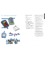
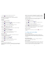
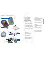
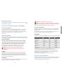
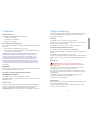
Tx-1, Tx-5 and Tx-10 transmitters
1
3
2
10
11
12 13 14
15
16
17
18
19
20
21
22
Transmitter features
1. Keypad.
2. LCD.
3. Removable accessory tray.
4. D-cell battery tray.
5. Rechargeable battery pack
(Optional).
Transmitter keypad
6. Power key : Switches the unit on
and off. Opens the transmitter menu.
7. Frequency key
: Selects frequency.
Menu navigation key.
8. Up and down arrows
: Adjusts
the output signal. Scrolls through the
menu options.
9. Measure key
: Opens a sub menu.
Used to take voltage and impedance
measurements.
Transmitter screen icons
10. Battery icon: Indicates the battery level.
11. Alphanumeric description of selected
operation mode.
12. Standby icon: Appears when the
transmitter is in Standby mode.
13. Output level: Displays transmitter
output power.
14. Clamp icon: Indicates when a clamp or
other plug is connected.
15. DC icon: Appears when the transmitter
is powered from a DC source.
16. Induction indicator: Appears when the
transmitter is in Induction mode.
17. A-Frame (Tx-5 and Tx-10 only):
Indicates when the transmitter is in
Fault-Find mode.
18. CD Mode indicator (Tx-10 only):
Indicates that the transmitter is in
Current Direction mode. For use with
RD8000
™
locators only.
19. Voltage warning indicator: Indicates
that the transmitter is outputting
potentially hazardous voltage levels.
20. Volume icon: Displays the volume level.
21. Pairing icon (Tx-5B and Tx-10B only):
For use with RD8000 locators only.
22. Bluetooth icon (Tx-5B and Tx-10B only).
For use with RD8000 locators only.
5
4
6
7
8
9

ENGLISH
10 11
Before you begin
IMPORTANT! This guide is intended to be a quick reference guide. We recommend
you read the operation manual before you attempt to operate the RD7000+ locator!
First use
For safety reasons RD7000+ locators are shipped with the Li-Ion battery packs
disconnected and transmitters with no D cells in the battery tray.
To connect the Li-Ion battery pack open the RD7000+ battery compartment and plug the
battery lead into the battery connector.
To fit the D cell batteries in the transmitter, unlatch the accessory tray. The battery
compartment is located underneath the transmitter body. Use the turnkey to unlatch
the battery compartment. Insert eight D-Cell Alkaline or NiMH batteries.
System setup
It is important that you set up the system according to your personal preferences and
operating requirements before you conduct your first survey. You can set the system up
using the RD7000+ menu as described below.
NOTE: These procedures refer to both the transmitter and locator unless stated
otherwise.
Before changing settings, switch the locator or transmitter on by pressing the
key.
NOTE: Once the system is switched on, pressing the
key momentarily will
activate the locator or transmitter menu.
Using the menus
The RD7000+ locator and transmitter menus allow you to select or change system options.
Once entered, the menu is navigated using the arrow keys. Navigation is consistent on both
the transmitter and the locator. When in the menu, most on-screen icons will temporarily
disappear and the menu options will appear in the bottom left-hand corner of the display.
Note that when browsing the locator menu, the
and keys act as left and right arrows.
When browsing the transmitter menu the
and keys act as left and right arrows. The
right arrow enters a submenu and the left arrow returns to the previous menu.
NOTE: When you select an option and press the
key, the option will be enabled
automatically.
Locator menu options
• VOL: Adjust the speaker volume from 0 (mute) to 3 (loudest).
• BT: Enable, disable, reset or pair Bluetooth connections. Also defines the protocol
used when connecting to a PC or PDA.
• UNITS: Select metric or imperial units.
• CAL: Displays the date of original factory calibration and the most recent service
calibration or eCert calibration validation.
• MARKR: Enable or disable individual utility markers.
• LANG: Select menus language.
• POWER: Select power frequency: 50 or 60Hz.
• ANT: Enable or disable any antenna mode with the exception of Peak.
• FREQ: Enable or disable individual frequencies.
• ALERT: Enable or disable StrikeAlert
™
.
• BATT: Set battery type: ALK, NiMH or Li-ION.
• COMP: Enable or disable display of the Compass feature.
To navigate the locator menu:
1. Press the key to enter the menu.
2. Use the
or
keys to scroll through the menu options.
3. Press the
key to enter the option’s submenu.
4. Use the
or
keys to scroll through the submenu options.
5. Press the
key to confirm a selection and return to the previous menu.
6. Press the
key to return to the main operation screen.
Transmitter menu options
• VOL: Adjust the speaker volume from 0 (mute) to 3 (loudest).
• FREQ: Enable or disable individual frequencies.
• BOOST: Boost transmitter output for a specified period of time (in minutes).
• LANG: Select menus language.
• OPT F: Enable or disable SideStepauto
™
.
• BATT: Set battery type: ALK, NiMH or Li-ION – Also select Eco mode for alkaline
batteries only.
• MAX P: Allow the transmitter to output its maximum wattage.
• MODEL: Specify the model of your locator.
• MAX V: Set the output voltage.
• BT: Enable, disable or pair Bluetooth connections to a RD8000 locator (Bluetooth
models only).
To navigate the transmitter menu:
1. Press the key to enter the menu.
2. Use the
or
keys to scroll through the menu options.
3. Press the
key to enter the option’s submenu.
4. Use the
or
keys to scroll through the submenu options.

ENGLISH
12 13
5. Press the
key to return to the previous level or exit the menu.
6. Press the
key to return to the main operation screen.
Examples of using the menu, selecting options
and making changes:
Language
To select your preferred menu language:
1. Press the
key to enter the menu.
2. Scroll to the LANG menu using the
or keys.
3. Press the
key (on the locator) or the key (on the transmitter) to enter the LANG menu.
4. Scroll up or down to select your preferred language.
5. Press the
key to accept your selection and return to the main menu.
6. Press the
key to return to the main operation screen.
Power / mains frequency (locator only)
To select the correct frequency (50 or 60Hz) for your country or region’s power supply:
1. Press the
key to enter the menu.
2. Scroll to the POWER menu using the
or keys.
3. Press the
key to enter the POWER menu.
4. Scroll up or down to select the correct frequency.
5. Press the
key to accept your selection and return to the main menu.
6. Press the
key to return to the main operation screen.
Units (locator only)
The RD7000+ locator allows you to work in Metric or Imperial (US customary) units.
To select your preferred units of measurements:
1. Press the
key to enter the menu.
2. Scroll to the UNIT option using the
or keys.
3. Press the
key to enter the UNIT submenu.
4. Scroll up or down to select Metric or Imperial units.
5. Press the
key to accept your selection and return to the main menu.
6. Press the
key to return to the main operation screen.
Batteries
The locator and transmitter are battery powered.
The RD7000+ locators are provided with a rechargeable Lithium-ion (Li-Ion) battery pack as
standard. The RD7000+ locators can also be powered using good quality D-cell alkaline or
NiMH batteries.
Transmitters can be powered by D-cell alkaline batteries (as standard), D-cell NiMH
batteries, or by an optional accessory Li-Ion battery pack. Alternatively, you can power
the transmitter from a mains or vehicle power source using a Radiodetection supplied
optional accessory adapter.
If using D-Cells it is important to set the system to match the currently installed battery
type to ensure optimal performance and correct battery level indication.
To set your battery type:
1. Press the
key to enter the menu.
2. Scroll to the BATT menu using the
or arrows.
3. Press the
key (on the locator) or the key (on the transmitter) to enter the
BATT menu.
4. Scroll up or down to select the correct battery type.
5. Press the
key to accept your selection and return to the main menu.
6. Press the
key to return to the main operation screen.
When using alkaline batteries Eco mode can be selected to maximize their usage. When
Eco mode is selected the transmitter automatically reduces its max power output when
the batteries cannot longer supply enough energy.
Shutting down
To switch the locator or the transmitter off, press and hold the key until the screen
goes blank.
Locating pipes and cables
Passive Frequencies
Passive frequency detection takes advantage of signals that are already present on
buried metallic conductors. The RD7000+ supports three types of passive frequencies:
power, radio, CPS (DL models only). You can detect these frequencies without the aid of
the transmitter.
Active Frequencies
Active frequencies are applied direct to the pipe or cable using the transmitter. The
transmitter can apply a signal using three methods:
Direct connection
In direct connection, you connect the transmitter directly to the pipe or cable you wish to
survey. The transmitter will then apply a discrete signal to the line, which you can trace
using the locator. This method provides the best signal on an individual line and enables
the use of lower frequencies, which can be traced for longer distances.

ENGLISH
14 15
Connecting the transmitter to a pipe or line requires the use of a direct connection lead
and a ground stake to complete the circuit.
WARNING! Direct connection to live conductors is POTENTIALLY LETHAL. Direct
connections to live conductors should be attempted by fully qualified personnel only
using the relevant products that allow connections to energized lines.
Induction
The transmitter is placed on the ground over or near the survey area. You select the
appropriate frequency. The transmitter will then induce the signal indiscriminately to
any nearby metallic conductor. In induction mode, using higher frequencies is generally
recommended as they are induced more easily onto nearby conductors.
Clamp
The optional signal clamp can be used to apply the transmitter signal to an insulated live
wire or pipe up to 8.5"/215mm in diameter.
WARNING! Do not clamp around uninsulated live conductors.
WARNING! Before applying or removing the clamp around a power cable ensure
that the clamp is connected to the transmitter at all times.
Refer to the Signal Clamps paragraph in the Using Accessories section.
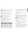
Locating RF Markers
The RD7000+ locator enables users to locate most common RF utility markers. These
are also referred to as Electronic Marker System (EMS) and Omni markers.
To enable marker locate mode lower the marker loop antenna. To disable the marker
locate mode fold the loop antenna up.
Marker types
The RD7000+ can detect 9 different RF Markers, as shown in the table below.
UTILITY COLOR DISPLAY FREQUENCY
ABBREVIATION
French Power Natural PFR 40.0kHz
General / Non-drinkable water Purple PUR 66.35kHz
Cable TV Black/Orange CTV 77.0kHz
Gas Yellow GAS 83.0kHz
Telephone/Telecoms Orange TEL 101.4kHz
Sanitary Green SAN 121.6kHz
German Power Blue/Red PDE 134.0kHz
Water Blue H20 145.7kHz
Electrical Power* Red PWR 169.8kHz
*Use of the red Electrical Power (PWR) marker locate mode is subject to radio licensing restrictions
for Short Range Devices in the EU and possibly other countries. It is the responsibility of the user
to ensure that the red Power (PWR) marker locate mode is only enabled in countries where radio
licensing restrictions do not apply at the operating frequency of 169kHz.
If required and permitted use RD Manager to enable this frequency.
Using accessories
The locator and transmitter are compatible with a wide range of accessories. For detailed
information on using any of the accessories below please refer to the RD7000+ locator
operation manual.
Signal clamps
When it is not possible to connect directly onto a pipe or cable, or induction mode is
unsuitable, a transmitter signal clamp may be used. The clamp is plugged into the output
of the transmitter and provides a means of applying a locate signal to an insulated live
wire. This is particularly useful with live insulated cables as it removes the need to disable
the power and break the line.
WARNING! Do not clamp around uninsulated live conductors.
WARNING! Before applying or removing the clamp around a power cable ensure
that the clamp is connected to the transmitter at all times.
To locate or identify individual lines a locator signal clamp can be connected to the
accessory socket of the locator and can be clamped around individual pipes or cables.
Stethoscopes
At times, it may not be possible to use a clamp around a cable because of congestion
or inaccessibility. A stethoscope antenna should be used in place of a clamp to identify
cables.
Radiodetection supplies a range of stethoscopes to suit most applications.
To use a stethoscope, connect it to the locator’s accessory socket. The locator will
automatically detect the device and filter out location modes that are irrelevant.
Sondes and FlexiTrace
Sondes are battery powered transmitters that are useful for tracing non-metallic pipes.
The RD7000+ can detect a range of sonde frequencies, including those transmitted by
Flexisondes, GatorCam
™
4 or flexiprobe
™
pushrod systems and P350 flexitrax
™
crawlers.
For a detailed guide on locating sondes, please refer to the operation manual.
A FlexiTrace is a traceable fiberglass rod incorporating wire conductors with a sonde
at the end. It is connected to the output of the transmitter and is typically used in small
diameter, non-metallic pipes. The user has the option of locating the entire length of the
cable or choosing to locate only the tip of the cable.

ENGLISH
16 17
The FlexiTrace has a maximum power rating of 1W. When using the FlexiTrace with a
Radiodetection Tx-5(B) or Tx-10(B) transmitter the output limit must be set to 1W in the
MAX P menu and the output voltage limit set to LOW in the MAX V menu.
No settings are required for the Tx-1 transmitter.
WARNING: Failure to follow the Tx-5(B) or Tx-10(B) instructions above may
result in the tip of the FlexiTrace becoming too hot to touch, resulting in risk of
personal injury and damage to the equipment.
Fault-finding with an A-Frame
The RD7000+ PLM and TLM models have the ability to detect cable sheath faults
accurately using an A-Frame accessory. The Tx-5 and Tx-10 provide a fault finding signal
that can be detected by the A-Frame as a result of the signal bleeding to ground through
damaged cable sheaths.
For a detailed guide to fault-finding, please refer to the operation manual.
Plug / Live cable connector
The plug connector is connected to the output of the transmitter and is used to put a signal
onto a line and trace it from a domestic mains plug to the service cable in the street.
The live cable connector can be used to apply a signal to a live cable. Only suitably
qualified personnel should use this equipment.
Submersible Double Depth Antenna
This antenna is connected to the locator and used to locate pipes and cables underwater
at depths down to 100 metres.
WARNING: use of the submersible antenna should be by fully licensed and
experienced personnel only, and only after fully reading the operation manual!
Transmitter Rechargeable battery packs
Rechargeable battery packs for the transmitter are available and are supplied with suitable
chargers. The rechargeable battery packs provide superior performance over traditional
alkaline batteries.
Bluetooth wireless connections
RD7000+ locators feature a Bluetooth wireless module, as standard, providing the ability
to connect to compatible devices such as PCs, laptops or handheld devices running a
compatible application.
NOTE: The RD7000+ locator wireless features may be subject to national and or
local regulations. Please consult your local authorities for more information.
WARNING! Do not attempt any wireless connection in areas where such
technology is considered hazardous. This may include: petrochemical facilities,
medical facilities or around navigation equipment.
Switching Bluetooth on
By default RD7000+ locators and Bluetooth enabled transmitters are shipped with the
Bluetooth wireless connection module disabled.
1. Press the
key to enter the menu.
2. Scroll to the BT menu using the
or keys.
3. Press the
key (locator) or the key (transmitter) to enter the BT menu.
4. Scroll up or down to the ON option.
5. Press the
key to switch Bluetooth ON and return to the previous menu.
Switching Bluetooth off
You can switch Bluetooth off to prolong battery life or comply with regulations in areas
where wireless communications are considered hazardous.
1. Press the
key to enter the menu.
2. Scroll to the BT menu using the
or keys.
3. Press the
key (locator) or the key (transmitter) to enter the BT menu.
4. Scroll up or down to the OFF option.
5. Press the
key to switch Bluetooth off and return to the previous menu.
Pairing to a PDA or PC
Connection requirements:
• Any RD7000+ locator.
• A compatible Bluetooth enabled PDA or Bluetooth enabled PC or Laptop.
NOTE: The procedure below describes the pairing process between a RD7000+
locator and a PDA. Pairing to a PC follows the same steps for the RD7000+ locator
and similar steps for your PC or laptop. Consult your PC or laptop Bluetooth pairing
instructions to pair with the RD7000+ locator.
Pair the RD7000+ locator to your PDA using your PDA’s Bluetooth software.
NOTE: The procedure for pairing your PDA may differ depending on the PDA make
and model. The following procedure should apply to most PDAs.
On the locator:
1. Press the
key to enter the menu.
2. Scroll to the BT menu using the
or keys.
3. Press the
key to enter the BT menu.
4. Scroll up or down to the PAIR menu.

ENGLISH
18 19
5. Press the key to enter the PAIR menu.
6. Scroll up or down to the BT-PC option.
7. Press the
key and the locator will attempt to pair with your PDA.
On your PDA:
8. From the PDA’s Start menu, select Settings then select the Connections Tab
followed by the Bluetooth icon.
9. Ensure the Bluetooth radio is switched on and make the PDA visible to other devices.
10. Select the Devices tab and scan for new partnerships.
11. Create a partnership with the RD7M_xxx device.
12. If asked for a passkey, enter 1234.
13. Select the COM Ports tab and make a New Outgoing Port with the RD7000+
locator. Note the port number of the selected COM port.
Troubleshooting
Successful wireless communication depends on a number of factors including:
battery life, electromagnetic interference, device memory and physical obstructions.
Ensure that the RD7000+ locator and any other wireless device is sufficiently charged
for wireless communication. Note that many PDAs will suspend wireless connections
when their battery capacity drops below a threshold percentage. Consult your device’s
documentation for more information.
Excessive electromagnetic interference can effectively limit the range of wireless
communication and / or corrupt data.
Your PDA device may have insufficient memory to maintain a wireless link, particularly if
the connection is sustained over an hour or longer. Make sure you quit applications on
your PDA using the method described in your device’s documentation.
Resetting connections
If you experience problems with the RD7000+ wireless Bluetooth technology features,
Radiodetection recommends resetting the connection and then pairing your device again:
1. Press the
key to enter the menu.
2. Scroll to the BT menu using the
or keys.
3. Press the
key to enter the BT menu.
4. Scroll up or down to the RESET menu.
5. Press the
key and the locator will purge all current connections.
6. Re-pair your devices.
Bluetooth error codes
If an error occurs when attempting to perform any Bluetooth command using the locator
to the transmitter or the locator to a PC or PDA, the LCD will display a code to help you
resolve the problem on the locator.
The codes are as follows:
BT CODE DESCRIPTION
BT001 Bluetooth not configured for this unit
BT002 Internal Bluetooth error
BT004 Locator not paired with PC/PDA
BT005 Paired but connection attempt failed. Power cycling may be required
Survey Measurements
The RD7000+ locator models can transmit survey measurements to a paired Pocket PC
(or PDA) with GPS, running a compatible application such as SurveyCERT.
Saving measurements
To save survey measurements, press the key.
To achieve accurate results the locator must be kept as still as possible during the saving
process.
If your PC or PDA is out of reach the locator will display an error code. To avoid these
errors disable the Bluetooth survey measurements transmission or ensure that your PC or
PDA is within range and correctly paired.
NOTE: A flashing depth and/or current reading display means that the
measurement is poor and should be taken again. Poor readings may be caused by
nearby conductors or sources of electromagnetic interference.
To obtain SurveyCERT for PDA:
SurveyCERT for PDAs and its operation manual are available as a free download from the
Radiodetection website:
1. Visit www.radiodetection.com.
2. Using the menu bar, go to Support -> SurveyCERT.
3. Click on the RD7000+ SurveyCERT link to get to the SurveyCERT download page
and follow the instructions.

ENGLISH
20 21
CALSafe
CALSafe enabled RD7000+ (PLM and TLM models only) are equipped with a system
which does not permit them to function once they are beyond the expected service/
calibration date.
When the unit is within 30 days of the service due date the unit will display at startup the
number of days left. The locator will stop functioning on the service due date.
You can edit the CALSafe service due date or disable this function using the RD Manager
PC software. Refer to its operation manual for further information.
Automatic Logging
RD7000+ logging models (PLM and TLM) offer a powerful data logging system which
records all the instrument’s critical parameters and warnings in its internal memory at the
rate of 1/sec.
The automatic logging system is always active and cannot be disabled. Its memory is
capable of storing at least 1 year’s worth of normal usage data – based on 4 hours
operation per day, 5 days per week, 20 days per month.
Logs can be retrieved using the RD Manager PC application for usage analysis and
survey validation. Refer to its operation manual for further information.
Important notices
When reporting any problems to your Radiodetection Dealer or Supplier it is important to
quote the unit serial number and the purchase date.
This instrument, or family of instruments, will not be permanently damaged by reasonable
electrostatic discharge and has been tested in accordance with IEC 801-2. However,
in extreme cases temporary malfunction may occur. If this happens, switch off, wait and
switch on again. If the instrument still malfunctions, disconnect the batteries for five
seconds and then reinstall and switch the unit on.
Compliance
EU Compliance
This equipment complies with the following EU Directives:
• R&TTE Directive: 1999/5/EC
• Low Voltage Directive: 2006/95/EC
• EMC Directive: 2004/108/EC
FCC Compliance Statement
This equipment complies with Part 15 of the FCC Rules. Operation is subject to the
following two conditions:
• The equipment may not cause harmful interference.
• The equipment must accept any interference received, including interference that
may cause undesired operation.
NOTE: This equipment has been tested and found to comply with the limits
for a Class A digital device pursuant to Part 15 of the FCC Rules. These limits
are designed to provide reasonable protection against harmful interference
when the equipment is operated in a commercial environment. This equipment
generates, uses, and can radiate radio frequency energy and, if not installed
and used in accordance with the manufacturer’s instruction manual, may cause
harmful interference with radio communications. Operation of this equipment in a
residential area is likely to cause harmful interference, in which case you will be
required to correct the interference at your own expense.
Modifications:
Any modifications made to this equipment not approved by Radiodetection may void the
authority granted to the user by the FCC to operate this equipment.
Industry Canada Compliance Statements
ICES-003 Class A Notice:
This Class A digital apparatus complies with Canadian ICES-003.
Avis NMB-003, Classe A: Cet appareil numérique de la classe A est conforme à la norme
NMB-003 du Canada.
Training
Radiodetection provides training services for most Radiodetection products. Our qualified
instructors will train equipment operators or other personnel at your preferred location or
at Radiodetection headquarters. For more information go to www.radiodetection.com or
contact your local Radiodetection representative.

ENGLISH
22 23
Care and maintenance
The RD7000+ locator and transmitter are robust, durable and weatherproof. However
you can extend your equipment’s life by following these care and maintenance guidelines.
General
Store the equipment in a clean and dry environment.
Ensure all terminals and connection sockets are clean, free of debris and corrosion and
are undamaged.
Do not use this equipment when damaged or faulty.
Batteries and power supply
Use good quality Alkaline or NiMH batteries only.
When using an AC adapter, use only Radiodetection approved adapters.
Only use Radiodetection approved Li-Ion battery packs.
Batteries should be disposed of in accordance with your company’s work practice, and/
or any relevant laws or guidelines in your country.
Cleaning
WARNING! Do not attempt to clean this equipment when it is powered or
connected to any power source, including batteries, adapters and live cables.
Ensure the equipment is clean and dry whenever possible.
Clean this equipment with soft, moistened cloth.
If using this equipment in foul water systems or other areas where biological hazards may
be present, use an appropriate disinfectant.
Do not use abrasive materials or chemicals as they may damage the casing, including the
reflective labels.
Do not use high pressure hoses.
Disassembly
Do not attempt to disassemble this equipment under any circumstances. The locator and
transmitter contain no user serviceable parts.
Disassembly may damage the equipment and or reduce its performance and may void the
manufacturer’s warranty.
Service and maintenance
The locator and transmitter are designed so that they do not require regular calibration.
However, as with all safety equipment, it is recommended that they are serviced at least
once a year either at Radiodetection or an approved repair center.
Regularly check your equipment using eCert; this automatic validation test ensures the
equipment is valid according to its original factory calibration.
NOTE: Service by non-approved service centers or operators may void the
manufacturer’s warranty.
Radiodetection products, including this guide, are under continuous development and are
subject to change without notice. Go to www.radiodetection.com or contact your local
Radiodetection representative for the latest information regarding the RD7000+ locator
or any Radiodetection product.
RD Manager
The RD Manager is the RD7000+ locator system PC companion and it allows you to
manage and customize your locator. It also allows software upgrades to both the locator
and transmitter.
You can use RD Manager to register your products to obtain 2 years extended warranty,
setup your locator by performing a number of maintenance tasks such adjusting date
and time, activating and de-activating active frequencies or RF markers, or by setting-up
functions like CALSafe or StrikeAlert.
RD Manager is also used to retrieve and analyze internal logged data (PLM and TLM
only).
RD Manager is compatible with PCs running Microsoft Windows XP, Vista, Windows 7
and Windows 8.
For more information about RD Manager refer to its operation manual.
To obtain RD Manager:
1. Go to www.radiodetection.com/RDManager.
2. Follow the instructions.
Software Upgrades
From time to time, Radiodetection may release software upgrades to enhance features
and improve performance of the RD7000+ locator or transmitter.
Software upgrades are free of charge.
You can check if your products are up-to-date or upgrade them by using the RD Manager
software upgrade screen. Refer to its operation manual for further information.
E-mail alerts and notification of new software releases are sent to all registered users.
NOTE: To be able upgrade your products software you need to have created an
account using RD Manager and you need a live internet connection. An optional
special PSU adaptor may be required to update your transmitter software.

ENGLISH
24 25
eCert
The RD7000+ locator is safety equipment which should be regularly checked to ensure
its correct operation.
eCert provides a thorough test of the RD7000+’s locating circuitry and marker
transceiver, and supplies a Radiodetection Calibration Certificate when a positive test
result is obtained.
To run eCert, the locator should be connected to an internet-enabled PC on which the
RD Manager software is installed. Additional purchase may be required.
Refer to the RD Manager operation manual for further details.
NOTE: eCert does not work with transmitters.
Warranty and extended warranty
RD7000+ locators and transmitters are covered by a 1 year warranty as standard.
Customers can extend the warranty period to a total of 3 years by registering their
products (locators and transmitters) within 3 months of purchase.
Registration is done using the RD Manager PC software.
From time to time Radiodetection may release new software to improve the performance
or add new functionality to its products. By registering, users will benefit from subscribing
to email alerts advising about any new software and special offers related to its product
range.
Users will be able to opt out at any moment from receiving software and technical
notifications or just from receiving marketing material.
Registering using email
You can also register your product(s) by sending an email to [email protected].
You will need to provide the following compulsory details:
1. Date of Purchase.
2. Serial Number of each of your qualifying products (RD7000+ locators and
transmitters).
3. Your email address.
4. Your Company Name.
5. Contact Name.
6. Address.
7. Telephone Number.
8. Country of residence.
9. Indicate that you do not wish to receive e-mail alerts advising about any new
software release (OPT OUT) – by default you will receive email notifications.
10. Indicate that you do not wish to receive e-mail or other marketing material with new
product information or special offers and promotions related to its product range
(OPT OUT) – by default you will receive marketing material.
Standard Warranty Terms
Subject to the conditions set out herein, Radiodetection Limited expressly and exclusively
provides the following warranty to original end user buyers of Radiodetection products.
Radiodetection hereby warrants that its products shall be free from defects in material
and workmanship for one year starting from point of sale to end customer. Extensions of
this warranty period are available where the same terms and conditions apply.
Statement of warranty conditions
The sole and exclusive warranty for any Radiodetection product found to be defective
is repair or replacement of the defective product at Radiodetection’s sole discretion.
Repaired parts or replacement products will be provided by Radiodetection on an
exchange basis and will be either new or refurbished to be functionally equivalent to new.
In the event this exclusive remedy is deemed to have failed of its essential purpose,
Radiodetection’s liability shall not exceed the purchase price of the Radiodetection
product. In no event will Radiodetection be liable for any direct, indirect, special,
incidental, consequential or punitive damages (including lost profit) whether based on
warranty, contract, tort or any other legal theory.
Warranty services will be provided only with the original invoice or sales receipt
(indicating the date of purchase, model name and dealer’s name) within the warranty
period. This warranty covers only the hardware components of the Radiodetection
product. Data storage media or accessories must be removed prior to submission of the
product for warranty service.
Radiodetection will not be responsible for loss or erasure of data storage media
or accessories. Radiodetection is not responsible for transportation costs and
risks associated with transportation of the product. The existence of a defect shall
be determined by Radiodetection in accordance with procedures established by
Radiodetection.
This warranty is in lieu of any other warranty, express or implied, including any implied
warranty of merchantability or fitness for a particular purpose.

ENGLISH
26 27
This warranty does not cover:
a. periodic maintenance and repair or parts replacement due to wear and tear
b. consumables (components that are expected to require periodic replacement during
the lifetime of a product such as non-rechargeable batteries, bulbs, etc.)
c. damage or defects caused by use, operation or treatment of the product inconsistent
with its intended use
d. damage or changes to the product as a result of:
i. misuse, including: - treatment resulting in physical, cosmetic or surface damage or
changes to the product or damage to liquid crystal displays
ii. failure to install or use the product for its normal purpose or in accordance with
Radiodetection’s instructions on installation or use
iii. failure to maintain the product in accordance with Radiodetection’s instructions
on proper maintenance
iv. installation or use of the product in a manner inconsistent with the technical or
safety laws or standards in the country where it is installed or used
v. virus infections or use of the product with software not provided with the product
or incorrectly installed software
vi. the condition of or defects in systems with which the product is used or
incorporated except other ‘Radiodetection products’ designed to be used with
the product
vii. use of the product with accessories, peripheral equipment and other products of
a type, condition and standard other than prescribed by Radiodetection
viii. repair or attempted repair by persons who are not Radiodetection warranted and
certified repair houses
ix. adjustments or adaptations without Radiodetection’s prior written consent,
including:
i. upgrading the product beyond specifications or features described in the
instruction manual, or
ii. modifications to the product to conform it to national or local technical or
safety standards in countries other than those for which the product was
specifically designed and manufactured
x. neglect e.g. opening of cases where there are no user replaceable parts
xi. accidents, fire, liquids, chemicals, other substances, flooding, vibrations, excessive
heat, improper ventilation, power surges, excess or incorrect supply or input
voltage, radiation, electrostatic discharges including lighting, other external forces
and impacts.
©2017 Radiodetection Ltd. All rights reserved. Radiodetection is a subsidiary of SPX Corporation. RD7000, RD8000, SurveyCERT, eCert,
StrikeAlert, SideStep, CALSafe, RD Manager, flexiprobe, GatorCam, flexitrax and Radiodetection are either trademarks of Radiodetection
in the United States and/or other countries. The Bluetooth word mark and logos are owned by the Bluetooth SIG, Inc. and any use of such
marks by Radiodetection is under license. Microsoft and Windows are either registered trademarks or trademarks of Microsoft Corporation in
the United States and/or other countries. Due to a policy of continued development, we reserve the right
to alter or amend any published specification without notice. This document may not be copied, reproduced,
transmitted, modified or used, in whole or in part, without the prior written consent of Radiodetection Ltd.

DEUTSCH
28 29
Einleitung
Über diese Anleitung
Vorsicht: In diesem Leitfaden werden die wesentlichen Bedienungsabläufe
für den Empfänger RD7000+ mit Sender beschrieben. Er enthält außerdem
wichtige Sicherheitsinformationen und -richtlinien. Deshalb muss er komplett
durchgelesen werden, bevor der Empfänger RD7000+ mit Sender verwendet wird.
Dieser Leitfaden ist nur als Kurzübersicht zum Mitführen gedacht. Für detailliertere
Informationen, einschließlich für den Einsatz von Zubehör, Hilfe bei eCert
™
, CALSafe
™
*,
SurveyCERT
™
und automatischer Protokollierung*; nutzen Sie bitte die RD7000+
Bedienungsanleitung, SurveyCERT und RD-Manager
™
Beschreibungen, welche als
Download unter www.radiodetection.com zur Verfügung steht.
Die Online-Bibliothek enthält auch Links zu SurveyCERT und RD-Manager
Beschreibungen.
*Nur für Protokollierung Modelle.
WARNUNG! Ein direkter Anschluss an stromführende Leitungen ist
LEBENSGEFÄHRLICH. Direkte Anschlüsse dürfen nur durch Fachpersonal
hergestellt werden.
WARNUNG! Der Sender kann lebensgefährliche Spannungen freigeben.
Seien Sie vorsichtig beim Anlegen von Signalen. Bitte informieren Sie alle
Techniker, die diese Linie nutzen.
WARNUNG! Reduzieren Sie die Lautstärke bevor Sie den Kopfhörer nutzen,
um Ihre Ohren zu schützen.
WARNUNG! Das System ist NICHT für Einsätze in explosionsgefährdeten
Bereichen zugelassen.
WARNUNG! Bei Verwendung des Senders das Gerät ausschalten und die
Kabel abziehen, bevor der Akkupack entfernt wird.
WARNUNG! Das RD7000+ erkennt praktisch alle unterirdisch verlegten Leiter.
Es gibt jedoch Objekte, die kein erkennbares Signal senden. Das RD7000+ oder
andere elektromagnetische Ortungsgeräte können diese Objekte nicht erkennen.
Gehen Sie daher mit Vorsicht vor. Es gibt auch stromführende Kabel, die das
RD7000+ im Strombetrieb nicht erkennen kann. Das RD7000+ zeigt nicht an,
ob ein Signal von einem Einzelkabel oder von mehreren Kabeln in unmittelbarer
Nähe kommt.
WARNUNG! Die Batterien können bei voller Nutzung heiß werden. Seien Sie
vorsichtig beim Ersetzen oder Handhabung der Batterien.
Erweiterte Garantie
Vielen Dank für den Kauf des Empfängers RD7000+ mit Sender.
Die Garantiezeit für den Empfänger RD7000+ mit Sender beträgt 1 Jahr.
Kunden können ihr Produkt (Empfänger und Sender) durch Registrierung die
Garantiezeit auf 3 Jahre verlängern.
Die Registrierung kann mit der RD Manager Software durchgeführt werden,
die Sie auf der Radiodetection Website downloaden können. Besuchen Sie
www.radiodetection.com/RDManager.
Von Zeit zu Zeit werden neue Softwareupdates zur Verbesserung der
Funktionalität von Radiodetection zur Verfügung gestellt. Nach erfolgter
Registrierung erhalten alle Anwender per E-Mail eine Mitteilung über spezielle
Angebote zur Produktgruppe.
Anwender sind somit in der Lage jederzeit aktuelle Informationen über technische
Neuerungen zu erhalten.
eCert
Der RD7000+ Empfänger ist eine Sicherheitsausrüstung, die regelmäßig
überprüft werden sollten, um die korrekte Funktion gewährleisten zu können.
eCert bietet eine gründliche Prüfung des RD7000+, die die Ortungs-
Schaltkreise und Marker-Transceiver überprüft und bei positivem Testergebnis
ein Radiodetection Kalibrierungszertifikat ausstellt.
Damit eCert einwandfrei genutzt werden kann, sollte die RD-Manager-Software
auf einem internetfähigen PC installiert sein. Ggfs. ist ein separater Kauf
notwendig.
Nähere Details zum RD-Manager finden Sie in der detaillierten Bedienungsanleitung.

DEUTSCH
30 31
5
6
7
9
3
2
4
8
10
11
12
13 14
1512
1
16
17 181821
30
32
19
20
22
23
24 25 26 27 2831 29
Empfänger RD7000+
Empfänger Funktionen
1. Tastenfeld
2. LCD-Anzeige
3. Lautsprecher
4. Batteriefach
5. Batterieladeanschluss
6. Zubehöranschluss
7. Kopfhöreranschluss
8. Bluetooth-Modul-Antenne
9. Marker-Rahmenantenne
Tastatur Empfänger
10. Ein-/Ausschalttaste : Schaltet
die Einheit ein oder aus. Öffnet das
Empfänger-Menü.
11. Frequenz-Taste
: Auswahl der
Frequenz. Schließen des Untermenüs.
12. Auf-/Ab-Pfeiltasten
: Einstellen
der Signalstärke. Scrollen durch die
Menüoptionen.
13. Antennentaste
: Bei ausgeklappter
Antenne schaltet das Gerät in den
Markermodus. Das Untermenü wird
gestartet.
14. Grafik-Taste
: Speichert die Messungen
durch SurveyCERT.
15. Sender-Taste
: Nicht verwendet.
Bildschirmsymbole des
Empfängers
16. Anzeige der Signalstärke und der
Spitzenmarke
17. Signalstärke: Numerische Anzeige der
Signalstärke
18. Links-/Rechts-Proportional-Pfeile:
Anzeige der georteten Leitung mit
Entfernungsrelation zum Ortungsgerät
19. Batterieanzeige: Anzeige des
Akkuladestands
20. Lautstärkeanzeige: Anzeige der Lautstärke.
21. Fehlersuch-Pfeile (mur PLM- und TLM-
Modelle).
22. Radio-Modus: Anzeige bei aktivem Radio-
Modus
23. Strom-Modus: Anzeige bei aktivem Strom-
Modus.
24. Zubehör-Anzeige: Gibt an, wenn Zubehör
angeschlossen ist oder Messungen aktiv
sind.
25. Rahmenantennen-Symbol: Zeigt an, wenn
die Rahmenantenne angeschlossen ist.
26. Anzeige der Betriebsart / Menüanzeige
27. Bluetooth
®
-Anzeige: Versuchte
Verbindungsaufnahme wird durch Blinken
des Symbols angezeigt. Ein nicht blinkendes
Symbol zeigt eine aktive Verbindung an.
28. Antennen-Betriebsanzeige: Zeigt die Wahl
der Antenne an: Spitze, Null und kombiniert
Spitze/Null.
29. Sonden-Symbol: Zeigt an, dass die
Signalquelle eine Sonde ist (DLM, PLM
und TLM-Modelle).
30. Leitungsortungssymbol: Zeigt an, dass
Leitungsortung gewählt wurde.
31. Kompass/Marker: Zeigt die Richtung
des georteten Kabels in Relation zum
Ortungsgerät an. Wird auch als graphische
Indikation für aktiven Marker verwendet.
32. Strom-/Tiefenanzeige.

DEUTSCH
32 33
Sender Tx-1, Tx-5 und Tx-10
1
3
2
10
11
12 13 14
15
16
17
18
19
20
21
22
5
4
6
7
8
9
Sender-Merkmale
1. Tastenfeld
2. LCD-Anzeige
3. Abnehmbare Zubehörbox
4. D-Zellen-Batterienfach
5. Akku-Pack (optional)
Sender-Tastenfeld
6. Ein-/Ausschalt-Taste : Ein-/
Ausschalten des Senders (lang
drücken) oder Zugang zum Sender-
Menü (kurz drücken). Öffnen des
Sender-Menüs.
7. Frequenz-Taste
: Auswahl der
Frequenz Menü-Navigationstaste.
8. Auf-/Ab-Pfeiltasten
: Einstellen
des Ausgangssignals / Scrollen durch
die Menüoptionen.
9. Mess-Taste
: Öffnet ein Untermenü
und mißt die Spannung.
Bildschirmsymbole des
Senders
10. Batterieanzeige: Anzeige des
Akkuladestands
11. Alphanumerische Anzeige der
gewählten Einstellung
12. Bereitschaftssymbol: Erscheint,
wenn der Sender in den
Bereitschaftsbetrieb versetzt wurde.
13. Ausgangsleistung: Zeigt die
Ausgangsleistung des Senders an.
14. Zangensymbol: Erscheint, wenn
eine Zange oder ein anderer
Steckverbinder angeschlossen wird.
15. DC-Symbol: Erscheint, wenn der
Sender an eine Gleichstromversorgung
angeschlossen ist.
16. Induktionsanzeige: Erscheint, wenn der
Sender im Induktionsbetrieb arbeitet.
17. A-Rahmen (nur Tx-5 und Tx-10):
Erscheint, wenn der Sender im
Fehlersuchebetrieb ist.
18. CD-Betriebsanzeige (nur Tx-10):
Zeigt an, dass der Sender in den
Signalstromrichtungsbetrieb geschaltet
ist. Nur für die Nutzung mit RD8000
™
-
Empfängern.
19. Spannungsanzeige: Zeigt an, dass
am Ausgang des Senders Spannung
anliegt.
20. Lautstärkeanzeige: Anzeige der
Lautstärke
21. Verbindungsanzeige (nur Tx-5B
und Tx-10B). Nur für die Nutzung mit
RD8000-Empfängern.
22. Bluetooth-Anzeige (nur Tx-5B und
Tx-10B). Nur für die Nutzung mit
RD8000-Empfängern.

DEUTSCH
34 35
Erste Schritte
WICHTIG! Dieser Leitfaden soll eine kurze Einführung sein. Wir empfehlen Ihnen,
die Bedienungsanleitung zu lesen, bevor Sie den RD7000+-Empfänger benutzen!
Bei der ersten Verwendung
Aus Sicherheitsgründen werden RD7000+ Empfänger getrennt von den Li-Ion-Akkus
und der Sender ohne D-Zellen im Batteriefach ausgeliefert.
Um die Li-Ion Batterien einzulegen, öffnen Sie das RD7000+ Batteriefach und schließen
Sie das Batteriekabel an den Batterieanschluss an.
Damit die D-Zellen Batterien in den Sender passen, entriegeln Sie die Zubehörablage. Das
Batteriefach befindet sich unter dem Senderkörper. Verwenden Sie den Drehverschluss um
das Batteriefach zu entriegeln. Legen Sie acht D-Cell Alkaline-oder NiMH-Akkus ein.
Systemeinrichtung
Es ist wichtig, dass Sie das System nach Ihren persönlichen Vorlieben und
Betriebsanforderungen einstellen, bevor Sie Ihre erste Ortung durchführen. Sie können das
System einrichten über das Menü Marker RD7000+-Empfänger wie unten beschrieben.
Hinweis: Dieses Verfahren bezieht sich sowohl auf den Sender und den Empfänger
sofern nicht anders angegeben.
Bevor Sie Einstellungen veränderen, schalten Sie den Empfänger oder den Sender an mit
der Ein-/Ausschalttaste
.
HINWEIS: Wenn das System einmal eingeschaltet ist, drücken Sie die Ein-/
Ausschalttaste
augenblicklich wird das Empfänger- oder Sender-Menü aktiviert.
Verwenden des Menüs
Über die Menüs des Empfängers RD7000+ können Sie Systemoptionen wählen oder
ändern. In den Menüs verwenden Sie die Pfeiltasten zur Navigation. Die Navigation verläuft
bei Sender und Empfänger nach dem gleichen Schema. Beim Aufrufen des Menüs werden
die meisten Bildschirmsymbole vorübergehend ausgeblendet und die Menüoptionen
werden links unten auf dem LCD-Bildschirm angezeigt. Beachten Sie, dass die Tasten
und
beim Durchsuchen als linke und rechte Pfeiltasten dienen. Beim Empfänger sind
die linken
und rechten Pfeiltasten nur aktiv, wenn Sie sich im Menü befinden. Mit der
rechten Pfeiltaste öffnen Sie ein Untermenü und mit der linken Pfeiltaste übernehmen Sie
die Auswahl und kehren in das vorhergehende Menü zurück.
HINWEIS: Wenn Sie eine Option wählen und die linke Pfeiltaste drücken, wird die
Option automatisch aktiviert.
Menüoptionen am Empfänger
• VOL: Einstellen der Lautstärke von 0 (stumm) bis 3 (sehr laut).
• BT: Einschalten, Ausschalten, Zurücksetzen oder Verbinden über Bluetooth. Definiert
auch die Protokoll-Nutzung bei Verbindung zu einem PC oder PDA.
• UNITS: Auswahl der Maßeinheit (metrisch oder imperial).
• CAL: Anzeige des Datums der ursprünglichen Werkskalibrierung und der aktuellsten
eCAL.
• MARKR: Aktivieren oder deaktivieren Sie einzelne Marker.
• LANG: Auswahl der gewünschten Sprache (DEU für Deutsch).
• POWER: Auswahl der örtlichen Stromfrequenz: 50 oder 60 Hz.
• ANT: Ein-/Ausschalten des Antennenbetriebs, mit Ausnahme der Spitzensignalortung.
• FREQ: Aktivieren bzw. Deaktivieren von individuellen Frequenzen.
• ALERT: Ein- bzw. Ausschalten von StrikeAler t
™
.
• BATT: Auswahl des Batterietyps: NiMH, ALK oder Li-ION.
• COMP: Einschalten oder Abschalten der Anzeige der Kompass-Funktion.
Navigieren im Empfängermenü:
1. Drücken Sie kurz die Taste , um das Menü zu öffnen.
2. Drücken Sie die
oder
-Tasten, um durch die Menüoptionen zu blättern.
3. Drücken Sie die Taste
, um das gewünschte Untermenü zu öffnen.
4. Verwenden Sie die
oder
-Tasten, um durch die Untermenüoptionen zu blättern.
5. Mithilfe der Taste
wird Ihre Auswahl bestätigt und Sie kehren zur vorherigen
Menüebene zurück.
6. Drücken Sie die Taste
, um zum Hauptarbeitsbildschirm zurückzukehren.
Menüoptionen am Sender
• VOL: Einstellen der Lautstärke von 0 (stumm) bis 3 (sehr laut).
• FREQ: Aktivieren und Deaktivieren von individuellen Frequenzen.
• BOOST: Anheben der Ausgangsleistung für einen bestimmten Zeitraum
(einstellbar in Minuten).
• LANG: Auswahl der Sender-Systemsprache.
• OPT F: Ein-/Ausschalten der SideStepAuto
™
-Funktion.
• BATT: Auswahl des Batterietyps: NiMH, ALK oder Li-ION.
• MAX P: Auswahl der Ausgangsleistung.
• MODELL: Spezifiziert das Modell Ihres RD7000+ Ortungsgeräts.
• MAX V: Auswahl der Ausgangsspannung.
• BT: Aktivieren, Deaktivieren oder Herstellen der Bluetooth-Verbindungen zu einem
RD8000 Empfänger (nur bei BT-Versionen verfügbar).

DEUTSCH
36 37
Navigieren im Sendermenü:
1. Drücken Sie kurz die Taste , um das Menü zu öffnen.
2. Verwenden Sie die Pfeiltasten
oder
, um durch die Menüoptionen zu blättern.
3. Drücken Sie die Taste
, um das gewünschte Untermenü zu öffnen.
4. Verwenden Sie die Pfeiltasten
oder
, um durch die Untermenüoptionen zu
blättern.
5. Mithilfe der Taste
wird Ihre Auswahl bestätigt und Sie kehren zur vorherigen
Menüebene zurück.
6. Drücken Sie die Taste
, um zum Hauptarbeitsbildschirm zurückzukehren.
Beispiele für das Verwenden des Menüs, das
Auswählen von Optionen und das Durchführen von
Änderungen:
Sprache
Zur Einstellung Ihrer gewünschten Menüsprache:
1. Drücken Sie kurz die Taste
, um das Menü zu öffnen.
2. Scrollen Sie mit Hilfe der Pfeiltasten im Menü bis zur Option LANG (Sprache).
3. Drücken Sie die Taste
(Taste am Sender), um das Untermenü LANG
(Sprache) zu öffnen.
4. Scrollen Sie mit
und nach oben oder unten, um die gewünschte Sprache zu
wählen.
5. Drücken Sie die Taste
, um Ihre Auswahl zu übernehmen und in das Hauptmenü
zurückzukehren.
6. Drücken Sie die Taste
, um zum Hauptarbeitsbildschirm zurückzukehren.
Strom und Hauptfrequenzen
Wählen Sie die richtige Frequenz (50 oder 60 Hz) entsprechend der Stromversorgung
Ihres Landes oder Ihrer Region. Wählen der Netzfrequenz am Ortungsgerät:
1. Drücken Sie kurz die Taste
um das Menü zu öffnen.
2. Scrollen Sie mit Hilfe der Pfeiltasten zur Option POWER (Strom).
3. Scrollen Sie mit den Pfeiltasten
oder nach oben oder unten, bis POWER
(Strom) angezeigt wird.
4. Drücken Sie die Taste
, um das STROM-Untermenü zu öffnen.
5. Scrollen Sie mit den Pfeiltasten
oder nach oben oder unten, um die richtige
Frequenz zu wählen.
6. Drücken Sie die Taste
, um Ihre Auswahl zu bestätigen. Das Gerät kehrt jetzt zum
Ausgangsbildschirm zurück.
Maßeinheiten (nur Empfänger)
Sie können mit dem RD7000+ in metrischen oder in britischen (bzw. amerikanischen)
Maßeinheiten arbeiten. Zur Auswahl der gewünschten Maßeinheiten gehen Sie bitte
folgendermaßen vor:
1. Drücken Sie kurz die Taste
, um das Menü zu öffnen.
2. Scrollen Sie mit Hilfe der Pfeiltasten zur Option POWER (Strom).
3. Scrollen Sie mit den Pfeiltasten
oder nach oben oder unten, bis POWER
(Strom) angezeigt wird.
4. Drücken Sie die Taste
, um das STROM-Untermenü zu öffnen.
5. Scrollen Sie mit den Pfeiltasten
oder nach oben oder unten, um die richtige
Frequenz zu wählen.
6. Drücken Sie die Taste
, um Ihre Auswahl zu bestätigen. Das Gerät kehrt jetzt zum
Ausgangsbildschirm zurück.
Batterien
Der Empfänger und Sender sind batteriebetrieben.
Die RD7000+-Empfänger werden standardmäßig mit einer Lithium-Ionen-(Li-Ion)
Batterie-Pack ausgeliefert. Die RD7000+-Empfänger können auch mit hochwertigen
D-Cell Alkaline-oder NiMH-Batterien betrieben werden.
Der Sender kann standardmäßig mit D-Zellen-Alkaline-Batterien, D-Zellen-NiMH-
Batterien oder optional mit Li-Ionen-Akku betrieben werden. Alternativ können Sie
den Sender mit einer Netz- oder Fahrzeugstromquelle mit einem von Radiodetection
gelieferten optionales Zubehör-Adapter betrieben werden.
Bei der Verwendung von D-Cells ist es wichtig, das System auf die derzeit installierte
Akku-Typ zu setzen, um eine optimale Leistung und richtige Batteriestandsanzeige
sicherzustellen.
Zur Auswahl des Batterietyps gehen Sie folgendermaßen vor:
1. Drücken Sie kurz die Taste
, um das Menü zu öffnen.
2. Scrollen Sie mit den Pfeiltasten
oder zur Option BATT (Batterie).
3. Drücken Sie die Taste
(Taste am Sender), um das Untermenü BATT (Batterie)
zu öffnen.
4. Scrollen Sie nach oben oder unten, um den gewünschten Batterietyp zu wählen.
5. Drücken Sie die Taste
, um Ihre Auswahl zu übernehmen und in das Hauptmenü
zurückzukehren.
6. Drücken Sie die Taste
, um zum Hauptarbeitsbildschirm zurückzukehren.
Bei der Verwendung von Alkali-Batterien kann der Eco-Modus ausgewählt werden, um
deren Nutzung zu maximieren. Beim Eco-Modus reduziert der Sender automatisch seine
Leistung, wenn die Batterien nicht mehr ausreichend Energie liefern.

DEUTSCH
38 39
Das Herunterfahren
Um den Empfänger oder den Sender auszuschalten, drücken und halten Sie die Taste ,
bis der Bildschirm schwarz wird.
Orten von Rohrleitungen und Kabeln
Passive Frequenzen
Passive Frequenzortung hat den Vorteil, dass die Signale auf den meisten erdverlegten
Kabeln und Leitungen schon vorhanden sind. Das RD7000+ hat vier verschiedene
Ortungsfrequenzen zur Verfügung: Strom- und Funksignale, CPS*- und CATV*-Signale.
Sie können diese Frequenzen orten, ohne einen Sender nutzen zu müssen.
*Modellspezifisch.
Aktive Frequenzen
Aktive Frequenzen werden mit Hilfe des Senders direkt oder induktiv auf eine Leitung oder
ein Kabel aufgebracht. Der Sender kann auf drei verschiedene Arten ein Signal übertragen:
Direkte Ankopplung
Bei der direkten Ankopplung wird der Sender direkt mit der Leitung oder dem Kabel
verbunden. Der Sender erzeugt ein Signal, welches über die Leitung bzw. das Kabel
übertragen wird und mit Hilfe des Ortungsgeräts geortet werden kann. Diese Methode
liefert das beste Signal auf einer einzelnen Leitung und ermöglicht die Verwendung
niedrigerer Frequenzen, die über größere Entfernungen geortet werden können.
Um den Sender an eine Rohrleitung oder ein Kabel anzuschließen, muss ein
Verbindungskabel an die Zubehörbuchse des Senders angeschlossen werden.
WARNUNG! Ein direkter Anschluss an stromführende Leitungen ist
LEBENSGEFÄHRLICH. Direkte Anschlüsse dürfen nur durch Fachpersonal
hergestellt werden.
Induktion
Der Sender wird auf den Boden in der Nähe der zu ortenden Umgebung aufgesetzt.
Wählen Sie eine entsprechende Frequenz. Der Sender wird diese Frequenz induktiv
auf alle metallischen Leitungen in der Nähe übertragen. Im Induktionsbetrieb wird die
Anwendung von höheren Frequenzen empfohlen, da diese Frequenzen sich leichter auf
metallische Leitungen übertragen lassen.
Sendezange
Die optionale Sendezange kann genutzt werden, um das Sendersignal zu einem isolierten
Live-Draht-oder Rohr bis zu 215 mm Durchmesser anzuwenden.
HINWEIS! Bei nicht isolierten Leitern nicht anklemmen.
HINWEIS Vor dem Anbringen oder Entfernen der Zange um ein Stromkabel
gewährleisten, dass die Zange die gesamte Zeit an den Sender angeschlossen ist.
Beachten Sie den Sendenzangen-Absatz unter Nutzung von Zubehör.
Ortung von Markern
Der RD7000+ Empfänger macht es Anwendern möglich, die meisten handelsüblichen
Marker zu orten. Diese werden auch als Electronic Marker System (EMS) und Omni
Marker bezeichnet.
Um die Markerortung zu ermöglichen, senken Sie die Marker-Rahmenantenne. Um die
Markerortung zu deaktivieren, klappen Sie die Rahmenantenne auf.
Markertypen
Der RD7000+ kann 9 verschiedene RF Marker orten – wie unten in der Tabelle beschrieben.
BRANCHE FARBE ANZEIGEN- FREQUENZ
ABKÜRZUNG
Frankreich Strom natur PFR 40.0 kHz
Wasser/Abwasser lila PUR 66.35 kHz
Kabel TV schwarz/orange CTV 77.0 kHz
Gas gelb GAS 83.0 kHz
Telefon/Telekom orange TEL 101.4 kHz
Sanitär grün SAN 121.6 kHz
Deutschland Strom blau/rot PDE 134.0 kHz
Wasser blau H20 145.7 kHz
Elektrische Energie* rot PWR 169.8 kHz
*Die Verwendung des roten Electrical Power (PWR) Markerortungmodus ist, die
Funkzulassungsbeschränkungen für Short Range Devices in der EU und möglicherweise
anderen Ländern. Es ist die Verantwortung des Anwenders sicherzustellen, dass die rote Power
(PWR) Markerortung nur in Ländern, in denen Funkzulassungsbeschränkungen nicht bei der
Betriebsfrequenz von 169 kHz gelten, aktiviert wird.
Bei Bedarf nutzen Sie den RD-Manager, um diese Frequenz zu ermöglichen.
Einsatz des Zubehörs
Der Empfänger und der Sender können mit verschiedenem Zubehör verbunden werden.
Einzelheiten zum Einsatz des nachfolgend beschriebenen Zubehörs finden Sie in der
ausführlichen Bedienungsanleitung für das RD7000+.
Seite wird geladen ...
Seite wird geladen ...
Seite wird geladen ...
Seite wird geladen ...
Seite wird geladen ...
Seite wird geladen ...
Seite wird geladen ...
-
 1
1
-
 2
2
-
 3
3
-
 4
4
-
 5
5
-
 6
6
-
 7
7
-
 8
8
-
 9
9
-
 10
10
-
 11
11
-
 12
12
-
 13
13
-
 14
14
-
 15
15
-
 16
16
-
 17
17
-
 18
18
-
 19
19
-
 20
20
-
 21
21
-
 22
22
-
 23
23
-
 24
24
-
 25
25
-
 26
26
-
 27
27


Radiodetection RD7000 Plus Benutzerhandbuch
- Typ
- Benutzerhandbuch
in anderen Sprachen
Verwandte Artikel
Andere Dokumente
-
Greenlee EML100 Marker-Mate Electronic Marker Locator Benutzerhandbuch
-
Amprobe A-5000 Sheath Fault Locator Benutzerhandbuch
-
-
Steinberg Nuendo 4.0 Quick Start
-
C.Scope SGA4 Benutzerhandbuch
-
Yamaha AW2400 Benutzerhandbuch
-
Hexatronic LTT20000 Benutzerhandbuch
-
Wohler L 200 Bedienungsanleitung
-
Sonel LKZ-1000 Benutzerhandbuch
-
Extech Instruments CLT600 Quick Start