CAME TARGHA GSM VR Installationsanleitung
- Typ
- Installationsanleitung

TARGHA GSM VR 24809620 22-07-14
TARGHA GSM VR
24809620
Italiano
IT
English
EN
Français
FR
Deutsch
DE
Español
ES
www.bpt.it
TARGHA GSM VR1 TARGHA GSM VR2
TARGHA GSM VR4

2
A
D
F
C
E
B
a
521 811 1214
521 811 1214
AA AA
BA
AA
BA
CA
DA
AA AA
BA
AA
BA
CA
DA
G
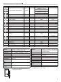
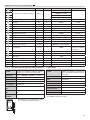
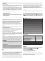
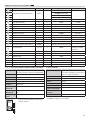
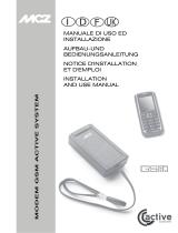
99 mm 22 mm
207 mm
45,5 mm
a
a

3
Avvertenze generali
• Leggere attentamente le istruzioni prima di iniziare l’installazione ed eseguire
gli interventi come specicato dal costruttore;
• L’installazione, la programmazione, la messa in servizio e la manutenzione del
prodotto deve essere eettuata soltanto da personale tecnico qualicato ed
opportunamente addestrato nel rispetto delle normative vigenti ivi comprese
le osservanze sulla prevenzione infortuni;
• Prima di eettuare qualunque operazione di pulizia o di manutenzione, to-
gliere l’alimentazione al dispositivo;
• L’apparecchio dovrà essere destinato unicamente all’uso per il quale è stato
espressamente concepito.
• Il mancato rispetto delle prescrizioni sopra elencate può compromettere la
sicurezza dell’apparecchio.
• Il costruttore non può comunque essere considerato responsabile per eventua-
li danni derivanti da usi impropri, erronei ed irragionevoli.
Informazioni sulla sicurezza
Il presente dispositivo è una radio ricetrasmittente a bassa potenza. Quando è
in funzione, invia e riceve energia a radiofrequenza (RF). Il dispositivo produce
campi magnetici, per questa ragione deve essere tenuto lontano da supporti
magnetici quali dischetti, nastri, ecc.
Il funzionamento del dispositivo vicino a dispositivi elettrici ed elettronici quali
radio, telefoni, televisioni e computer può causare interferenze.
Interferenze
Il presente dispositivo, così come tutti i dispositivi senza li, è soggetto a interfe-
renze che posso-no inuire sulle prestazioni del dispositivo.
Utilizzo all’interno degli Ospedali
È sconsigliabile l’utilizzo del dispositivo negli ospedali e nei centri sanitari, in
quanto è possibile che siano in uso dispositivi sensibili a segnali esterni di ra-
diofrequenza.
Utilizzo in prossimita’ di materiali esplosivi
Non utilizzate il dispositivo in depositi di carburante, impianti chimici o in aree
caratterizzate dalla presenza di gas esplosivi o dove sono in corso operazioni con
esplosivi. Sarà necessario rispetta-re le limitazioni e attenersi a qualunque nor-
ma o disposizione prevista.
Modalità uso
Non utilizzare il dispositivo a contatto col corpo umano, non toccare l’antenna
se non strettamente necessario. Utilizzate solo accessori approvati. Consultate
i manuali di eventuali altri dispositivi da collegare al presente dispositivo. Non
collegate dispositivi incompatibili.
SMALTIMENTO
Assicurarsi che il materiale d’imballaggio non venga disperso nell’ambiente,
ma smaltito seguendo le norme vigenti nel paese di utilizzo del prodotto.
Alla ne del ciclo di vita dell’apparecchio evitare che lo stesso venga disperso
nell’ambiente.
Lo smaltimento dell’apparecchiatura deve essere eettuato rispettando le
norme vigenti e privilegiando il riciclaggio delle sue parti costituenti.
Sui componenti, per cui è previsto lo smaltimento con riciclaggio, sono ripor-
tati il simbolo e la sigla del materiale.
y Nota
Prima di eseguire l’installazione è indispensabile vericare che, nel luogo in cui
si intende installare il dispositivo, vi sia un livello adeguato del segnale GSM: per
fare ciò è suciente inserire la SIM-CARD acquistata in un telefono cellulare e
vericarne la ricezione.
Nel caso la ricezione non risulti di buona qualità, sarà necessario installare il
dispositivo in un altro luogo, ove ci sia una migliore qualità del segnale oppure
utilizzare in alternativa l’antenna esterna.
Resta inteso che la società BPT S.p.A. non assume alcuna responsabilità in re-
lazione al mancato invio, mancata ricezione o ritardato invio o ritardata rice-
zione del messaggio SMS da parte del posto esterno, quando si tratti di fatto
imputabile alla ricezione del relativo segnale o a problemi di qualunque tipo che
attengano all’attività del gestore di telefonia;
Le SIM-CARD di alcuni Provider sono soggette a scadenza: si consiglia di tenerne
conto al momento della programmazione del posto esterno.
Descrizione
TARGHA GSM VR è un sistema citofonico GSM, in grado di eettuare chiamate
audio in modalità viva voce, a numeri telefonici di rete mobile e rete ssa con
la pressione dei pulsanti.
Attraverso 2 relè montati a bordo, si possono comandare l’apertura di una porta
o di un cancello a distanza, digitando (in conversazione) il tasto per il relè 1
ed il tasto per il relè 2 dalla tastiera del proprio telefono.
Con i messaggi SMS, inne, è possibile programmare, gestire e chiedere infor-
mazioni relative al parametro prescelto.
MAX 4 pulsanti di chiamata (1, 2 oppure 4)
Memoria no a 20 numeri telefonici (5 per ogni utenza)
Ripetizioni di chiamata no a 9 (loop sequenza)
Sequenza di chiamata non variabile
Minuti di conversazione no a 9 (hang-up automatico)
Pulsanti escludibili
Audio esterno escludibile no alla risposta
Password di sistema variabile
Test pulsanti
Test relè
Audio esterno regolabile
Invio e ricezione SMS
Modem GSM/GPRS Quad Band 900/1800 MHz
Alloggiamento microSIM card tipo Push-Push
Indicatori Luminosi: Alimentazione e status (all’interno del modulo)
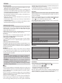
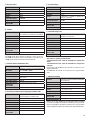
Dati tecnici
Tipo TARGHA GSM VR1-2-4
Alimentazione max [VDC] 12- 26
Consumo in stand-by a 18 V [mA] 30
Consumo in chiamata a 18 V[mA] 300
Potere d’interruzione [mA] max 50 V 500
Lunghezza cavo antenna [m] 3
Range di temperatura [°C] -15 / +50
Grado di protezione [IP] 54
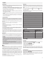
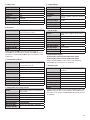
Dimensioni
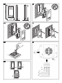
Installazione
Le fasi di installazione della TARGHAVR GSM comprendono:
• Fissaggio a muro della base da parete o da incasso ;
• Inserimento della carta SIM a a;
• Collegamento dell’alimentazione ed eventuali relè;
• Programmazione e congurazione tramite SMS;
Dopo aver estratto il prodotto dalla confezione, vericarne l’integrità. Prima di
collegare l’alimentazione, è necessario inserire la carta SIM nel dispositivo e una
volta acceso vericare la copertura di rete attraverso il led stato rete.
Italiano

4
Inserimento della carta SIM
Prima di iniziare l’installazione del prodotto, inserisci la carta SIM nell’apposito
alloggiamento presente all’interno del posto esterno a a.
TARGHAVR GSM supporta qualsiasi SIM del tipo PLUG-IN (3V/1,8V). Al ne di
evitare il danneggiamento della SIM o la perdita di informazioni consigliamo di
non toccare la parte dorata della SIM (dove sono presenti i contatti).
Attenzione
Vericate con l’operatore telefonico che la SIM sia abilitata al traco SMS. Vi
consigliamo di controllarne il corretto funzionamento usandola su un normale
telefono cellulare; in modo particolare è importante:
• disabilitare la richiesta del codice PIN ad ogni accensione;
• provare un invio ed una ricezione di messaggi SMS;
In caso di problemi:
• Vericate il credito residuo (nel caso di SIM prepagate);
• Vericate ed eventualmente inserire il numero del Centro Servizi (fate riferi-
mento all’operatore telefonico).
Probabilmente la SIM card Vi sarà fornita su un supporto compatibile con i dispo-
sitivi che utilizzano la SIM full-size.
1. Staccate la SIM con cautela dal supporto per farla diventare delle dimensioni
PLUG-IN.
2. Assicuratevi che il dispositivo sia spento, scollegando l’alimentazione.
3. Individuate l’alloggiamento della SIM.
4. Inserite la SIM nello specico porta SIM con i contatti rivolti verso il basso, e
vericando che l’angolo tagliato sia posizionato in modo corretto.
5. Fate scivolare nell’apposito alloggio la SIM premendo no in fondo. In caso
di dicoltà non forzate assolutamente il porta SIM, ma vericatene il corretto
posizionamento.
Collegamento antenna esterna
Terminata la fase di installazione della SIM, potete collegare l’antenna esterna:
assicuratevi che il dispositivo sia spento, scollegando l’alimentazione; inserire
il connettore dell’antenna esterna al connettore del modem GSM no al bloc-
caggio.
In caso di dicoltà non forzate assolutamente il connettore ma vericatene il
corretto posizionamento.
La TARGHAVR GSM è pronta ad operare in modo ottimale solo al termine della
registrazione alla rete GSM, e con una buona qualità del segnale GSM.
E’ possibile vericare il segnale GSM in 2 modalità:
· Attraverso un telefono cellulare
· Attraverso il LED GSM
Alimentazione
Attenzione. La tensione di alimentazione non deve superare il valore massimo
indicato, pena il danneggiamento del prodotto stesso.
Dare alimentazione soltanto quando l’installazione è completata, quindi tutti i
collegamenti sono stati eseguiti correttamente.
Messa in servizio
Terminata l’installazione, sarà necessario programmare il prodotto. Durante la
prima accensione vericare i led di illuminazione tasti. Dopo 45 secondi dall’ac-
censione, il posto esterno sarà registrato alla rete, il led inizierà a lam-
peggiare lentamente; nel caso in cui il led rimanga acceso in modo permanente,
spegnete e vericate:
• Il corretto inserimento della SIM nell’alloggiamento;
• La disabilitazione della richiesta del codice PIN;
• La qualità del segnale GSM, inserendo la stessa carta SIM in un telefono cellu-
lare;
• L’antenna esterna collegata in modo errato.
Resta inteso che la società Bpt S.p.A. a Socio Unico non si assume alcu-
na responsabilità in relazione ai seguenti eventi:
• mancato invio, mancata ricezione o ritardato invio o ritardata rice-
zione del messaggio SMS da parte del posto esterno, quando si tratti
di fatto imputabile alla ricezione del relativo segnale o a problemi di
qualunque tipo che attengano all’attività del gestore di telefonia;
• addebito sul credito residuo della SIM del posto esterno di costi de-
rivanti da messaggi provenienti dal gestore di telefonia mobile o da
altri servizi eettuati dal gestore di telefonia mobile.
Sostituzione cartellino portanome
Per scrivere i dati desiderati sul cartellino portanome, estrarre il ferma cartellino
e quindi il cartellino.
Si possono utilizzare cartellini portanome personalizzati no ad un massimo di
2mm di spessore.
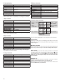
Connessioni
a Slot ingresso SIM-Card;
LED GSM;
Ingresso Antenna;
Pulsante di reset;
Morsettiera
Positivo Alimentazione;
Negativo Alimentazione;
Comune relè 1;
NO relè 1;
Comune relè 2;
NO relè 2;
Configurazione
La congurazione di TARGHA GSMVR viene eettuata con l’invio di semplici mes-
saggi SMS da un normale telefono cellulare, verso il numero telefonico della SIM
CARD inserita nel prodotto.
I comandi di congurazione vengono accettati e memorizzati dal po-
sto esterno solo se il messaggio SMS viene preceduto dal PIN (default
0000) di sistema corretto, altrimenti il messaggio verrà ignorato. TAR-
GHA GSMVR, alla ricezione corretta del messaggio di testo SMS e nei
casi in cui è previsto, risponde, attraverso un messaggio SMS, al mit-
tente confermando l’avvenuta congurazione del comando.

5
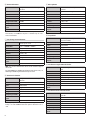
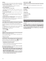
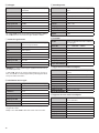
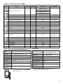
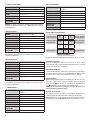
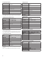
Congurazione pulsanti per la programmazione F
Comando Parametro Range Default Esempio SMS Note
Assocciazione pulsanti - numeri telefonici A-B-C-D -
0000AA[numero cellulare]
-
0000BA[numero cellulare]
0000CA[numero cellulare]
0000DA[numero cellulare]
Cicli di chiamata 1-9 1 0000G1 -
Timeout chiamata 1-9 3 0000H1 1=1min
Tono di ring 0-1 1 0000I1 0=O 1=On
Timeout tra chiamate 1-9 9 0000K9 9=45 sec
Blocco pulsante 0-1 1 0000LAA1 0=O
Test pulsante - - 0000MAA -
Cancellazione singolo numero - - 0000NAA1 1=Posizione 1
Cancellazione totale numeri - - 0000O*# -
Password 4 DIGIT 0000 0000P1234 -
Apricancello 0-2 0 0000Q1 0=O 1=Relè 2=Relè
Invio automatico sms credito 0-30 0 0000T0 0=Inattivo
Numero ricezione sms credito 16 DIGIT - 0000U[numero ricezione sms credito] -
Scelta lingua 0-1-2-3-4 0 0000V0
0=Italiano 1=Inglese
2=Francese 3=Tedesco
4=Spagnolo
Volume altoparlante 1-9 7 0000X7 -
Guadagno microfono 0-9 7 0000Y7 0=Mute
Qualità segnale - - 0000Z-
* Attivazione relè 1 - - 0000*-
# Attivazione relè 2 - - 0000#-
** Tempo chiusura relè 1 0-9 3 0000**3 0=Disabilitato 3=3 sec
## Tempo chiusura relè 2 0-9 3 0000##3 0=Disabilitato 3=3 sec
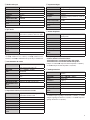
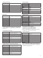
Associazione pulsanti di chiamata e numeri telefonici
Funzione Congurare e/o modicare i numeri telefonici conte-
nuti e associati ai pulsanti (AA no a DA)
Sintassi SMS <pin><comando><posizione><nr telefono>
<pin> 0000 (Default)
<comando> AA, BA, CA, DA oppure aa,ba,ca,da
<posizione> 1, 2, 3, 4, 5
<nr telefono> max 14 cifre
Esempio sintassi
SMS
0000AA13331234567
Esempio risposta
SMS
Numeri associati ad AA:
349.......
SMS automatico di
risposta
Si
1 BA1
2BA2
3BA3
4BA4
5BA5
1AA1
2AA2
3AA3
4AA4
5AA5
Per ogni tasto è possibile memorizzare un massi-
mo di 5 numeri di cellulare.
Cicli di chiamata
Funzione Congurare e/o modicare i cicli di chiamata
dei numeri telefonici, nel caso l’utente non ri-
sponda ad una chiamata
Sintassi SMS <pin><comando><valore>
<pin> 0000 (Default)
<comando> G oppure g
<valore> 1, 2, 3, 4, 5, 6, 7, 8, 9
Esempio sintassi SMS 0000G1
Esempio risposta SMS 1
SMS automatico di ri-
sposta
Si
Default 1
Esempio: con l’ SMS 0000G1 si imposta 1 ciclo di chiamata;
con 0000G2 si imposta 2 cicli di chiamata

6
Timeout di chiamata
Funzione Congurazione e/o modica del tempo di con-
versazione
Sintassi SMS <pin><comando><valore>
<pin> 0000 (Default)
<comando> H oppure h
<valore> 1, 2, 3, 4, 5, 6, 7, 8, 9
Esempio sintassi SMS 0000H1
Esempio risposta SMS 1
SMS automatico di ri-
sposta
Si
Default 3
Con l’ SMS 0000H1 viene impostato ad 1 minuto il tempo di conversazione
della chiamata; con 0000H3 viene impostata a 3 minuti il tempo di conver-
sazione della chiamata.
Tono dei ring esterni di chiamata
Funzione Abilitare e/o disabilitare i ring di chiamata
esterni al posto esterno
Sintassi SMS <pin><comando><valore>
<pin> 0000 (Default)
<comando> I oppure i
<valore> 0=OFF, 1=ON
Esempio sintassi SMS 0000I1
Esempio risposta SMS ON oppure OFF
SMS automatico di ri-
sposta
Si
Default 1 (ON)
NOTA. I ring esterni di chiamata hanno valenza sia nelle chiamate in ingresso
che in uscita
Con l’ SMS 0000I0 vengono disabilitati i ring di chiamata esterni al posto esterno; con
0000I1 vengono abilitati i ring di chiamata esterni al posto esterno.
Timeout tra le chiamate
Funzione Congurazione della durata dello squillo di
chiamata
Sintassi SMS <pin><comando><valore>
<pin> 0000 (Default)
<comando> K oppure k
<valore> 1, 2, 3, 4, 5, 6, 7, 8, 9
Esempio sintassi SMS 0000K9
Esempio risposta SMS 9
SMS automatico di ri-
sposta
Si
Default 9 (45 secondi)
NOTA. Ogni step vale 5 secondi. Per esempio il valore 5 è uguale a 25 secondi.
Esempio: con l’ SMS 0000K6 la durata dello squillo di chiamata è di 30 se-
condi.
Blocco pulsante
Funzione Abilitare e/o disabilitare il pulsante di chiamata
desiderato
Sintassi SMS <pin><comando><pulsante><valore>
<pin> 0000 (Default)
<comando> L oppure l
<pulsante> AA, BA, CA,DA oppure aa, ba, ca, da
<valore> 0=OFF, 1=ON
Esempio sintassi SMS 0000LAA0
Esempio risposta SMS AA: OFF
SMS automatico di
risposta
Si
Default 1=ON
Test pulsante
Funzione Simulare la pressione del pulsante desiderato e
inviare una chiamata
Sintassi SMS <pin><comando><pulsante>
<pin> 0000 (Default)
<comando> M oppure m
<pulsante> AA, BA, CA,DA oppure aa, ba, ca, da
<valore> 0=OFF, 1=ON
Esempio sintassi SMS 0000MAA
Esempio risposta SMS Test switch
SMS automatico di
risposta
Si
Cancellazione singolo numero di telefono
Funzione Eliminazione singolo numero telefonico dal pul-
sante
Sintassi SMS <pin><comando><pulsante><posizione>
<pin> 0000 (Default)
<comando> N oppure n
<pulsante> AA, BA, CA,DA oppure aa, ba, ca, da
<posizione> 1, 2, 3, 4, 5
Esempio sintassi SMS 0000NAA1
Esempio risposta SMS Numeri associati ad AA:....
SMS automatico di ri-
sposta
Si
Cancellazione totale numeri di telefoni
Funzione Eliminazione di tutti i numeri telefonici associati
ai pulsanti
Sintassi SMS <pin><comando><valore>
<pin> 0000
<comando> O oppure o
<valore> *#
Esempio sintassi SMS 0000O*#
Esempio risposta SMS Intera rubrica cancellata
SMS automatico di ri-
sposta
Si

7
Modica valore ‘pin’
Funzione Congurazione e/o modica ‘pin’ di sistema
Sintassi SMS <pin><comando><valore>
<pin> 0000 (Default)
<comando> P oppure p
<valore> 4 cifre
Esempio sintassi SMS 0000P5555
Esempio risposta SMS Pin modicato. Nuovo pin: 5555
SMS automatico di ri-
sposta
Si
NOTA. Fino a 10.000 combinazioni possibili
Apricancello
Funzione Abilitazione della funzione apricancello tramite
squillo telefonico (eettuare almeno due squilli)
Sintassi SMS <pin><comando><valore>
<pin> 0000 (Default)
<comando> Q oppure q
<valore> 0, 1, 2, 3
Esempio sintassi SMS 0000Q1
Esempio risposta SMS Apricancello: Relay 1
SMS automatico di ri-
sposta
Si
Default 0
Esempio: con l’ SMS 0000Q0 si disabilita la funzione ‘apricancello’;
con 0000Q1 si abilita il relè 1 e si esclude il 2; con 0000Q2 si abilita il relè 2 e si
esclude il 1; con 0000Q3 si abilita la funzione ‘apricancello’ per entrambi i relè.
Invio automatico sms credito
Funzione Congurazione dell’invio automatico del credito
residuo al numero impostato in
Sintassi SMS <pin><comando><valore>
<pin> 0000 (Default)
<comando> T oppure t
<valore> O=funzione disabilitata; no a 30 step; 1 step=1
giorno
Esempio sintassi SMS 0000T30
Esempio risposta SMS Trasmissione automatica ogni 30 giorni
SMS automatico di ri-
sposta
Si
Default 0 (disabilitata)
Impostazione numero per la ricezione sms di credito
Funzione Congurazione numero telefonico per la ricezio-
ne automatica dell’sms di credito
Sintassi SMS <pin><comando><numero>
<pin> 0000 (Default)
<comando> U oppure u
<numero> Fino a 16 DIGIT
Esempio sintassi SMS 0000U3388619861
Esempio risposta SMS Numero ricezione automatica sms: 3388619861
SMS automatico di ri-
sposta
Si
Impostazione lingua
Funzione Congurazione lingua desiderata
Sintassi SMS <pin><comando><valore>
<pin> 0000 (Default)
<comando> V oppure v
<valore> O (italiano), 1 (inglese), 2 (francese), 3 (tedesco),
4 (spagnolo)
Esempio sintassi SMS 0000V0
Esempio risposta SMS Italiano
SMS automatico di ri-
sposta
Si
Default 0 (italiano)
Volume altoparlante
Funzione Congurazione e/o modica il volume esterno
dell’altoparlante
Sintassi SMS <pin><comando><valore>
<pin> 0000 (Default)
<comando> X oppure x
<valore> 1, 2, 3, 4, 5, 6, 7, 8, 9
Esempio sintassi SMS 0000X4
Esempio risposta SMS Volume altoparlante:1
SMS automatico di ri-
sposta
Si
Default 7
NOTA. Questo parametro può essere modicato anche in fase di con-
versazione tramite la tastiera del telefono:
- Premendo il tasto 1 si incrementa il volume dello speaker
- Premendo il tasto 4 si decrementa il volume dello speaker
Esempio: con l’ SMS 0000X1 si imposta il volume altoparlante a 1 (minimo);
con 0000X9 si imposta il volume altoparlante a 9 (massimo).
Guadagno microfono
Funzione Congurazione e/o modica della sensibilità del
microfono
Sintassi SMS <pin><comando><valore>
<pin> 0000 (Default)
<comando> Y oppure y
<valore> 0, 1, 2, 3, 4, 5, 6, 7, 8, 9
Esempio sintassi SMS 0000Y1
Esempio risposta SMS Guadagno microfono:1
SMS automatico di ri-
sposta
Si
Default 7
Esempio: con l’ SMS 0000Y0 si disabilita il guadagno del microfono (0=muto);
con 0000Y1 si imposta il guadagno del microfono a 1 (minimo); con 0000Y5
si imposta il guadagno del microfono a 5 (medio) e con 0000Y9 si imposta il
guadagno del microfono a 9 (massimo).

8
Qualità del segnale GSM
Funzione Visualizzazione della qualità del segnale GSM
Sintassi SMS <pin><comando>
<pin> 0000 (Default)
<valore> ‘range da...a’
Esempio sintassi SMS 0000Z
Esempio risposta SMS Livello segnale: 12
SMS automatico di ri-
sposta
Si
NOTA. Il comando ‘Z’ analizza la qualità del segnale GSM, e restituisce all’u-
tente un valore numerico: da 0-1 (minimo), da 17-23 (medio), da 31 (mas-
simo)
Attivazione relè 1
Funzione Attivazione del relè 1 tramite sms
Sintassi SMS <pin><comando>
<pin> 0000 (Default)
<comando> *
<valore> 0, 1, 2, 3, 4, 5, 6, 7, 8, 9
Esempio sintassi SMS 0000*
Esempio risposta SMS Attivazione relè 1
SMS automatico di ri-
sposta
Si
NOTA. L’attivazione del relè 1 può essere eettuata anche in fase di comuni-
cazione attiva premendo il pulsante * sulla propria tastiera telefonica.
Attivazione relè 2
Funzione Attivazione del relè 2 tramite sms
Sintassi SMS <pin><comando>
<pin> 0000 (Default)
<comando> #
<valore> 0, 1, 2, 3, 4, 5, 6, 7, 8, 9
Esempio sintassi SMS 0000#
Esempio risposta SMS Attivazione relè 2
SMS automatico di ri-
sposta
Si
NOTA. L’attivazione del relè 2 può essere eettuata anche in fase di comunica-
zione attiva premendo il pulsante # sulla propria tastiera telefonica.
Tempo di chiusura del relè 1
Funzione Congurazione e/o modica del tempo di chiu-
sura del relè 1
Sintassi SMS <pin><comando><valore>
<pin> 0000 (Default)
<comando> **
<valore> 0 (disabilitato), 1, 2, 3, 4, 5, 6, 7, 8, 9
Esempio sintassi SMS 0000**5
Esempio risposta SMS Tempo di chiusura relè: 5
SMS automatico di ri-
sposta
Si
Default 3
NOTA. Il valore viene espresso in secondi
Tempo di chiusura del relè 2
Funzione Congurazione e/o modica del tempo di chiu-
sura del relè 2
Sintassi SMS <pin><comando><valore>
<pin> 0000 (Default)
<comando> ##
<valore> 0 (disabilitato), 1, 2, 3, 4, 5, 6, 7, 8, 9
Esempio sintassi SMS 0000##5
Esempio risposta SMS Tempo di chiusura relè: 5
SMS automatico di ri-
sposta
Si
Default 3
NOTA. Il valore viene espresso in secondi
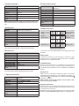
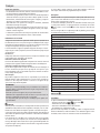
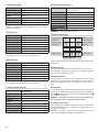
Comandi in conversazione
Aumenta volume
speaker 1 2 3 Aumenta sensibilità
del microfono
Dimunisce
volume speaker 4 5 6 Dimunisce sensibili-
tà microfono
7 8 9
Attivazione relè 1 * 0 #Attivazione relè 2
Chiusura della conversazione *
La conversazione viene chiusa tramite il pulsante ‘0’ solo sugli apparati telefonici
di rete ssa.
Volume Speaker
Se durante la conversazione, il nostro interlocutore non percepisce al giusto
volume la nostra voce è possibile aumentare, premendo il tasto ‘1’, o diminuire,
premendo il tasto ‘4’ , il volume dello speaker.
Sensibilità Microfono
Nel caso in cui non dovessimo ricevere correttamente la voce dell’interlocutore
di fronte alla postazione citofonica , possiamo intervenire premendo il tasto ‘3’
per aumentare oppure premendo il tasto ‘6’ per diminuirne la sensibilità del
microfono.
Attivazione relè
Tramite i due relè , possiamo pilotare l’apertura di un portone o di un cancello
automatizzato. Questa operazione può essere eettuata in conversazione pre-
mendo il pulsante per attivare il primo relè , oppure premendo il pulsante
per attivare il secondo relè.
NOTA: entrambi i relè non possono sopportare tensioni superiori a 60V e
correnti di carico superiori a 500mA.
Chiudere la conversazione
Questa funzione deve essere obbligatoriamente utilizzata quando il nostro di-
spositivo citofonico GSM contatta un numero di telefonia ssa. Premendo il tasto
‘0’ si interromperà la conversazione.
NOTA : Nel caso in cui non venga premuto il pulsante ‘0’ , la conversazione rimane
aperta no al tempo di TIMEOUT dell’apparato citofonico ( Vedi parametro ‘H’ ).

9
English
General Notes
• Read the instructions carefully before beginning the installation and carry out
the actions as specied by the maker;
• The installation, programming, putting into operation and maintenance of the
product must be carried out only by qualied technical personnel, correctly
trained with regard to respecting the regulations in force, including the imple-
mentation of accident prevention measures;
• Before carrying out any cleaning or maintenance operation, disconnect the
device from the power supply;
• The equipment must be destined solely for the use for which it was expressly
designed.
• Failure to comply with the above instructions may compromise the unit’s safety.
• The manufacturer declines all liability for any damage as a result of improper,
incorrect or unreasonable use.
Safety information
This device is a low power radio receiver-transmitter. When it is in operation, it
sends and receives energy by radio frequency (RF). The device produces mag-
netic elds, therefore it must be kept away from magnetic items such as disks,
tapes, etc.
Operating the device near to electrical and electronic devices such as radios,
telephones, televisions and computers can cause interference.
Interference
This device, like all wireless devices, is susceptible to interference which might
aect the performance of the device.
Use in Hospitals
It is not recommended that the device be used in hospitals and health centres,
given that devices sensitive to external radio frequency signals may be in use.
Use in proximity to explosive materials
Do not use the device in fuel storage depots, chemical factories or in areas where
explosive gases are present or where works using explosives are in progress. It
will be necessary to respect restrictions and comply with any standards or reg-
ulations in force.
Mode of use
Do not use the device in contact with the human body, do not touch the aerial unless
absolutely necessary. Use only approved accessories. Consult the manuals of any
other devices to be connected to this device. Do not connect incompatible devices.
DISPOSAL
Do not litter the environment with packaging material: make sure it is disposed
of according to the regulations in force in the country where the product is used.
When the equipment reaches the end of its life cycle, avoid discarding it in
the environment.
The equipment must be disposed of in compliance with the regulations in
force, recycling its component parts wherever possible.
Components that qualify as recyclable waste feature the relevant symbol and
material's abbreviation.
y Note
Before installing the device it is essential to check that there is an adequate GSM
signal in the place you intend to install it: to do this you just need to put the SIM-
CARD you purchased into a mobile phone and check its reception.
If the reception is not good, it will be necessary to install the device somewhere
else where there is a better signal, or alternatively to use an external aerial.
We would advise that BPT S.p.A. assumes no responsibility with regard to the
failed sending, failed receipt, delayed sending or delayed receipt of the SMS
message by the entry panel, when this can be attributed to reception of the
relative signal or to problems of any nature relating to the business of the tele-
phone provider;
Some Providers’ SIM-CARDs have expiry dates: it is recommended that you bear
this in mind when programming the entry panel.
Description
TARGHA GSM VR is a GSM audio entry system that can make audio calls in
speaker mode to telephone numbers on xed and mobile networks, by pressing
buttons.
Using 2 on-board relays, you can command the opening of a door or gate re-
motely, by pressing (during call) the key for relay 1 and the key for relay 2
on your phone’s keypad.
Finally, with SMS messages, you can programme, manage and ask for informa-
tion about the selected parameter.
MAX 4 call buttons (1, 2 or 4)
Memory of up to 20 telephone numbers (5 for each user)
Up to 9 call repetitions (loop sequence)
Invariable call sequence
Up to 9 minutes of conversation (automatic hang-up)
Buttons can be disabled
External audio can be disabled up to answering
Variable system password
Buttons test
Relay test
Adjustable external audio
Sending and receiving SMS
Quad Band 900/1800 MHz GSM/GPRS modem
Push-pull type microSIM card slot
Light Indicators: Power supply and status (inside module)
Technical data
Type TARGHA GSM VR1-2-4
Max power supply (VDC) 12- 26
Consumption in stand-by mode 18 V [mA] 30
Consumption during call 18 V [mA] 300
Breaking capacity [mA] max 50 V 500
Aerial cable length [m] 3
Temperature range [°C] -15 / +50
Protection rating [IP] 54
Dimensions
Installation
The installation stages for the TARGHAVR GSM include:
• Attachment to wall of the wall-mounted or recessed base ;
• Insertion of SIM card a a;
• Connection of power supply and any relays;
• Programming and settings via SMS;
After taking the product out of the box, check it is all intact. Before connect-
ing the power supply, the SIM card must be inserted into the device and once
switched on the network coverage must be checked via the network status LED.
Inserting SIM card
Before beginning the installation of the product, insert the SIM card into the slot
inside the entry panel a a.
TARGHAVR GSM supports any PLUG-IN type SIM (3V/1.8V). In order to avoid
damaging the SIM or losing information we recommend you do not touch the
gold part of the SIM (where the contacts are).

10
Warning
Check with the telephone provider that the SIM is enabled for SMS trac. We
recommend you check it is working correctly by using it in a normal mobile
phone; it is particularly important to:
• disable the request for the PIN number every time it is switched on;
• try out sending and receiving SMS messages;
In the event of problems:
• Check the remaining credit (on prepaid SIMs);
• Check and if necessary enter the number of the Service Centre (refer to the
phone provider).
The SIM card will probably be supplied to you in a holder that is compatible with
the devices that use full-size SIMs.
1. Carefully detach the SIM from the holder to make it the right size for the
PLUG-IN.
2. Make sure that the device is turned o, disconnecting the power supply.
3. Identify the SIM slot.
4. Insert the SIM in the specic SIM holder with the contacts downwards, check-
ing that the cut-o corner is correctly positioned.
5. Slide the SIM into the slot by pressing it down. If you have any diculty do not
force the SIM holder but check it is in the right position.
Connecting external aerial
Once installation of the SIM is completed, you can connect the external aerial:
make sure that the device is turned o, disconnecting the power supply; insert
the external aerial connector of the GSM modem connector until it locks.
If you have any diculty do not force the connector but check it is in the right
position.
The TARGHAVR GSM is ready for optimum operation only once registration with
the GSM network has been completed, and with a good GSM signal.
The GSM signal can be checked in 2 ways:
· Via a mobile phone
· Via the GSM LED
Power supply
Warning. The voltage supplied must not be greater than the maximum value
shown, or else the product may be damaged.
Power up only when installation has been completed, i.e. when all the connec-
tions have been made correctly.
Putting into operation
Once installation is completed, it will be necessary to reprogramme the product.
During rst switch-on check the key lighting LEDs. 45 seconds after switch-on,
the entry panel will be registered with the network, the LED will begin to
ash slowly; if the LED stays on permanently, turn o and check:
• The SIM has been inserted in the slot correctly;
• The PIN number request has been disabled;
• The quality of the GSM signal, by inserting the SIM card into a mobile phone;
• The external aerial has not been connected wrongly.
We would advise that BPT S.p.A. a Socio Unico assumes no responsibil-
ity in relation to the following events:
• failed send, failed receipt or delayed send or delayed receipt of the
SMS message by the entry panel, when this can be attributed to re-
ception of the relative signal or to problems of any nature relating to
the business of the telephone provider;
• charge to credit remaining on entry panel’s SIM of costs arising from
messages coming from the mobile phone provider or from other ser-
vices carried out by the mobile phone provider.
Replacing name card
To write the desired information on the name card, take out the card holder and
the card.
Personalised name cards up to a maximum thickness of 2mm can be used.
Connections
a SIM-Card input slot;
GSM LED;
Aerial Input;
Reset button;
Terminal board
Positive Power Supply;
Negative Power Supply;
Common relay 1;
NO relay 1;
Common relay 2;
NO relay 2;
Settings
Setting TARGHA GSMVR is carried out by sending simple SMS messages from
a normal mobile phone to the telephone number of the SIM CARD inserted in
the product.
The settings commands are accepted and stored by the entry panel
only if the SMS message is preceded by the correct system PIN (default
0000), otherwise the message will be ignored. TARGHA GSMVR, after
correctly receiving the SMS text message and in the cases for which
it is set up, answers the sender, via an SMS message, conrming the
command has been set up.

11
Setting buttons for programming F
Command Parameter Range Default Example SMS Notes
Association buttons - telephone numbers A-B-C-D -
0000AA[mobile number]
-
0000BA[mobile number]
0000CA[mobile number]
0000DA[mobile number]
Call cycles 1-9 1 0000G1 -
Call timeout 1-9 3 0000H1 1=1min
Ring tone 0-1 1 0000I1 0=O 1=On
Timeout between calls 1-9 9 0000K9 9=45 sec
Button lock 0-1 1 0000LAA1 0=O
Button test - - 0000MAA -
Deleting single number - - 0000NAA1 1=Position 1
Deleting all numbers - - 0000O*# -
Password 4 DIGIT 0000 0000P1234 -
Gate release 0-2 0 0000Q1 0=O 1=Relay 2=Relay
Send automatic credit sms 0-30 0 0000T0 0=O
Credit sms receipt number 16 DIGIT - 0000U[credit sms receipt number] -
Choose language 0-1-2-3-4 0 0000V0
0=Italian 1=English
2=French, 3=German,
4=Spanish
Speaker volume 1-9 7 0000X7 -
Microphone gain 0-9 7 0000Y7 0=Mute
Signal quality - - 0000Z-
* Relay 1 activation - - 0000*-
# Relay 2 activation - - 0000#-
** Relay 1 closure time 0-9 3 0000**3 0=Deactivated 3=3 sec
## Relay 2 closure time 0-9 3 0000##3 0=Deactivated 3=3 sec
Associating call buttons and telephone numbers
Function Setting up and/or editing the telephone numbers con-
tained and associated with the buttons (AA up to DA)
SMS Syntax <pin><command><position><telephone no>
<pin> 0000 (Default)
<command> AA, BA, CA, DA or aa,ba,ca,da
<position> 1, 2, 3, 4, 5
<telephone no> 14 digits max
SMS syntax example
0000AA13331234567
SMS reply example
Numbers associated to AA:
349.......
Automatic reply
SMS
Yes
1 BA1
2BA2
3BA3
4BA4
5BA5
1AA1
2AA2
3AA3
4AA4
5AA5
For each key a maximum of 5 mobile numbers
can be stored.
Call cycles
Function Setting up and/or editing the call cycles of
phone numbers, should the user not answer
the call
SMS Syntax <pin><command><value>
<pin> 0000 (Default)
<command> G or g
<value> 1, 2, 3, 4, 5, 6, 7, 8, 9
SMS syntax example 0000G1
SMS reply example 1
Automatic reply SMS Yes
Default 1
Example: with the SMS 0000G1 1 call cycle is set;
with 0000G2 2 call cycles are set;

12
Call timeout
Function Setting and/or editing call time
SMS Syntax <pin><command><value>
<pin> 0000 (Default)
<command> H or h
<value> 1, 2, 3, 4, 5, 6, 7, 8, 9
SMS syntax example 0000H1
SMS reply example 1
Automatic reply SMS Yes
Default 3
With SMS 0000H1 the call conversation time is set at 1 minute; with 0000H3
the call conversation time is set at 3 minutes.
External call ring tones
Function Enabling and/or disabling the external ring
tones at the entry panel
SMS Syntax <pin><command><value>
<pin> 0000 (Default)
<command> I or i
<value> 0=OFF, 1=ON
SMS syntax example 0000I1
SMS reply example ON or OFF
Automatic reply SMS Yes
Default 1 (ON)
NOTE. The external call rings are valid for both incoming and outgoing calls
With SMS 0000I0 the external call rings are disabled at the entry panel; with
0000I1 the external call rings are enabled at the entry panel.
Timeout between calls
Function Setting duration of call ring
SMS Syntax <pin><command><value>
<pin> 0000 (Default)
<command> K or k
<value> 1, 2, 3, 4, 5, 6, 7, 8, 9
SMS syntax example 0000K9
SMS reply example 9
Automatic reply SMS Yes
Default 9 (45 seconds)
NOTE. Each step is worth 5 seconds. For example value 5 is equal to 25 sec-
onds.
Example: with SMS 0000K6 the length of the call ring is 30 seconds.
Button lock
Function Enabling and/or disabling the desired call button
SMS Syntax <pin><command><button><value>
<pin> 0000 (Default)
<command> L or l
<button> AA, BA, CA,DA or aa, ba, ca, da
<value> 0=OFF, 1=ON
SMS syntax example 0000LAA0
SMS reply example AA: OFF
Automatic reply SMS Yes
Default 1=ON
Button test
Function Simulate pressing the desired button and send
a call
SMS Syntax <pin><command><button>
<pin> 0000 (Default)
<command> M or m
<button> AA, BA, CA,DA or aa, ba, ca, da
<value> 0=OFF, 1=ON
SMS syntax example 0000MAA
SMS reply example Switch test
Automatic reply SMS Yes
Deleting single telephone number
Function Deleting single telephone number from button
SMS Syntax <pin><command><button><position>
<pin> 0000 (Default)
<command> N or n
<button> AA, BA, CA,DA or aa, ba, ca, da
<position> 1, 2, 3, 4, 5
SMS syntax example 0000NAA1
SMS reply example Numbers associated to AA:
Automatic reply SMS Yes
Totally deleting telephone numbers
Function Deleting all the telephone numbers associated
to the buttons
SMS Syntax <pin><command><value>
<pin> 0000
<command> O or o
<value> *#
SMS syntax example 0000O*#
SMS reply example All contacts deleted
Automatic reply SMS Yes

13
Edit ‘pin’ value
Function Setting and/or editing system pin.
SMS Syntax <pin><command><value>
<pin> 0000 (Default)
<command> P or p
<value> 4 digits
SMS syntax example 0000P5555
SMS reply example Pin edited. New pin: 5555
Automatic reply SMS Yes
NOTE. Up to 10,000 possible combinations
Gate release
Function Enabling gate release function via telephone
ringing (let it ring at least twice)
SMS Syntax <pin><command><value>
<pin> 0000 (Default)
<command> Q or q
<value> 0, 1, 2, 3
SMS syntax example 0000Q1
SMS reply example Gate release: Relay 1
Automatic reply SMS Yes
Default 0
Example: with SMS 0000Q0 the 'gate release' function is disabled’;
with 0000Q1 relay 1 is enabled and 2 is disabled; with 0000Q2 relay 2 is ena-
bled and relay 1 is disabled; with 0000Q3 the 'gate release' function is enable
for both relays.
Send automatic credit sms
Function Setting up sending automatic remaining credit
sms to the number set in
SMS Syntax <pin><command><value>
<pin> 0000 (Default)
<command> T or t
<value>O=function disabled; up to 30 steps; 1 step=1
day
SMS syntax example 0000T30
SMS reply example Automatic transmission every 30 days
Automatic reply SMS Yes
Default 0 (disabled)
Setting number for receiving credit sms
Function Setting telephone number for automatically re-
ceiving credit sms
SMS Syntax <pin><command><number>
<pin> 0000 (Default)
<command> U or u
<number> Up to 16 DIGIT
SMS syntax example 0000U3388619861
SMS reply example Automatic sms receipt number: 3388619861
Automatic reply SMS Yes
Setting language
Function Setting language wanted
SMS Syntax <pin><command><value>
<pin> 0000 (Default)
<command> V or v
<value> O (Italian), 1 (English), 2 (French), 3 (German), 4
(Spanish)
SMS syntax example 0000V0
SMS reply example Italian
Automatic reply SMS Yes
Default 0 (Italian)
Speaker volume
Function Setting and/or modifying external volume of
speaker
SMS Syntax <pin><command><value>
<pin> 0000 (Default)
<command> X or x
<value> 1, 2, 3, 4, 5, 6, 7, 8, 9
SMS syntax example 0000X4
SMS reply example Speaker volume 1
Automatic reply SMS Yes
Default 7
NOTE. This parameter can also be modied during a conversation
using the telephone keypad:
- By pressing key 1 you increase the volume of the speaker
- By pressing key 4 you decrease the volume of the speaker
Example: with SMS 0000X1 the speaker volume is set at 1 (minimum);
with 0000X9 the speaker volume is set at 9 (maximum).
Microphone gain
Function Setting and/or modifying the sensitivity of the
microphone
SMS Syntax <pin><command><value>
<pin> 0000 (Default)
<command> Y or y
<value> 0, 1, 2, 3, 4, 5, 6, 7, 8, 9
SMS syntax example 0000Y1
SMS reply example Microphone gain 1
Automatic reply SMS Yes
Default 7
Example: with SMS 0000Y0 the microphone gain is disabled (0=mute); with
0000Y1 the microphone gain is set at 1 (minimum); with 0000Y5 the micro-
phone gain is set at 5 (average) and with 0000Y9 the microphone gain is set
at 9 (maximum).

14
GSM signal quality
Function Displaying GSM signal quality
SMS Syntax <pin><command>
<pin> 0000 (Default)
<value> ‘range from...to’
SMS syntax example 0000Z
SMS reply example Signal level: 12
Automatic reply SMS Yes
NOTE. The command ‘Z’ analyses the quality of the GSM signal, and returns a
numerical value to the user: 0-1 (minimum), 17-23 (average), 31 (maximum)
Relay 1 activation
Function Relay 1 activation via sms
SMS Syntax <pin><command>
<pin> 0000 (Default)
<command> *
<value> 0, 1, 2, 3, 4, 5, 6, 7, 8, 9
SMS syntax example 0000*
SMS reply example Relay 1 activation
Automatic reply SMS Yes
NOTE. Activating relay 1 can also be carried out during an active call by press-
ing the * button on your phone keypad.
Relay 2 activation
Function Relay 2 activation via sms
SMS Syntax <pin><command>
<pin> 0000 (Default)
<command> #
<value> 0, 1, 2, 3, 4, 5, 6, 7, 8, 9
SMS syntax example 0000#
SMS reply example Relay 2 activation
Automatic reply SMS Yes
NOTE. Activating relay 2 can also be carried out during an active call by press-
ing the # button on your phone keypad.
Relay 1 closure time
Function Setting and/or modifying relay 1 closure time
SMS Syntax <pin><command><value>
<pin> 0000 (Default)
<command> **
<value> 0 (disabled), 1, 2, 3, 4, 5, 6, 7, 8, 9
SMS syntax example 0000**5
SMS reply example Relay closure time: 5
Automatic reply SMS Yes
Default 3
NOTE. The value is expressed in seconds
Relay 2 closure time
Function Setting and/or modifying relay 2 closure time
SMS Syntax <pin><command><value>
<pin> 0000 (Default)
<command> ##
<value> 0 (disabled), 1, 2, 3, 4, 5, 6, 7, 8, 9
SMS syntax example 0000##5
SMS reply example Relay closure time: 5
Automatic reply SMS Yes
Default 3
NOTE. The value is expressed in seconds
Commands during conversation
Increase speaker
volume 123Increase micro-
phone sensitivity
Reduce
speaker volume 456Reduce microphone
sensitivity
789
Relay 1 activation * 0 #Relay 2 activation
Ending the call *
The call is ended by pushing button ‘0’ only on telephones on xed networks.
Speaker Volume
If during the call the person you are talking to cannot hear your voice at the
right volume, you can increase the speaker volume by pressing key 1, or lower
it by pressing key 4.
Microphone Sensitivity
If you can’t hear the voice of the person in front of the audio entry panel, you
can press key 3 to increase or key 6 to reduce the sensitivity of the microphone.
Relay activation
Via the two relays, you can control the opening of a front door or automated
gate. This operation can be carried out during a call by pressing the button
to activate the rst relay, or pressing the button to activate the second relay.
NOTE: both relays cannot support voltages above 60V and currents with a
load over 500mA.
Ending the call
This function must be used when your GSM audio receiver device contacts a
number on a xed line. By pressing key ‘0’ you will stop the call.
NOTE: If button ‘0’ is not pressed, the call will remain on the line until the audio
receiver’s TIMEOUT time ( See parameter ‘H’ ).

15
Français
Instructions générales
• Lire attentivement les instructions, avant de commencer l’installation et eec-
tuer les interventions comme indiqué par le fabricant;
• L’installation, la programmation, la mise en service et l’entretien du produit ne
doivent être eectuées que par un personnel technique qualié et convena-
blement formé, conformément aux normes légales en vigueur, y compris les
dispositions concernant la prévention des accidents;
• Avant d’eectuer toute opération de nettoyage ou d’entretien, débrancher
l’alimentation électrique de l’appareil;
• L’appareil doit être uniquement utilisé dans le but pour lequel il a été conçu.
• Le défaut de respect des prescriptions qui gurent ci-dessus peut compro-
mettre la sécurité de l’appareil.
• Le fabricant ne peut toutefois être tenu pour responsable des éventuels dom-
mages qui naîtraient d’une utilisation erronée ou déraisonnable.
Informations sur la sécurité
Cet appareil est un émetteur-récepteur radio à faible puissance. Quand il est en
fonctionnement, il envoie et reçoit de l’énergie en radiofréquence (RF). L’appa-
reil produit des champs magnétiques, pour cette raison, il doit être tenu à l’écart
des supports magnétiques tels que les disquettes, bandes, etc.
Le fonctionnement de l’appareil à proximité d’appareils électriques et électro-
niques tels que les radios, téléphones, téléviseurs et ordinateurs peut provoquer
des interférences.
Interférences
Ce dispositif, comme tous les appareils sans l, est sujet à des interférences qui
peuvent inuer sur les performances de l’appareil.
Utilisation à l’intérieur des hôpitaux
Il est déconseillé d’utiliser l’appareil dans les hôpitaux et les centres de santé où il
pourrait y avoir des appareils sensibles aux signaux externes en radiofréquence.
Utilisation à proximité de matériaux explosifs
Ne pas utiliser l’appareil dans les dépôts de carburant, les usines chimiques ou
les zones caractérisées par la présence de gaz explosifs ou lorsque des opéra-
tions de dynamitage sont en cours. Veuillez respecter les restrictions et suivre les
normes ou dispositions prévues.
Mode d’emploi
Ne pas utiliser l’appareil au contact avec le corps humain, ne pas toucher inu-
tilement l’antenne. Utiliser uniquement des accessoires agréés. Consulter les
manuels des autres dispositifs éventuels à connecter à cet appareil. Ne pas
connecter des dispositifs incompatibles.
ÉLIMINATION
Vérier que le matériel d'emballage n'est pas abandonné dans l'environne-
ment mais éliminé conformément aux normes légales en vigueur dans le pays
d'utilisation du produit.
À la n du cycle de vie de l'appareil, ne pas le jeter dans la nature.
L'élimination de l'équipement doit avoir lieu dans le respect des normes en
vigueur et en privilégiant le recyclage de ses composants.
Les composants prévus pour être recyclés sont indiqués par le symbole et le
sigle du matériau.
y Remarque
Avant de procéder à l’installation, il est indispensable de vérier que dans le lieu
d’installation du dispositif le niveau du signal GPS est adéquat: pour cela, il suf-
t d’insérer la carte SIM dans un téléphone portable et de vérier la réception.
Si la réception n’est pas de bonne qualité, il faudra installer le dispositif dans un
autre endroit où la qualité du signal sera meilleure ou bien utiliser en alternative
l’antenne externe.
Il est entendu que la société BPT S.p.A. ne saurait être tenue pour responsable
en cas de non-envoi, non-réception ou en cas d’envoi ou de réception diéré du
message SMS depuis l’unité externe dès lors qu’il s’agit d’un fait imputable à la
réception du signal ou à des problèmes de toute nature se rapportant à l’activité
de l’opérateur de téléphonie;
Les cartes SIM de certaines opérateurs ont une date d’expiration: veillez à en
tenir compte au moment de la programmation du poste externe.
Description
TARGHA GSM VR est un système d’interphone GSM capable d’eectuer des ap-
pels vocaux en mode mains libres vers des numéros de téléphone des réseaux
mobile ou xe en appuyant sur les boutons.
Les deux relais embarqués permettent de commander l’ouverture d’une porte
ou d’un portail à distance, en tapant (pendant la conversation) sur la touche
pour le relais 1 et sur la touche pour le relais 2 depuis le clavier de votre
téléphone.
Avec les messages SMS, il est également possible de planier, gérer et utiliser
des informations du paramètre sélectionné.
MAX 4 touches d'appel (1, 2 ou 4)
Répertoire jusqu'à 20 numéros de téléphone (5 pour chaque utilisateur)
Répétitions d'appel jusqu'à 9 (boucle séquence)
Séquence d'appel non modiable
Minutes de conversation jusqu'à 9 (raccrochage automatique)
Touches désactivables
Audio externe désactivable jusqu'à la réponse
Mot de passe système modiable
Test touches
Test relais
Audio externe réglable
Envoi et réception SMS
Modem GSM/GPRS Dual Band 900/1800 MHz
Emplacement carte micro-SIM de type Pousser-Pousser
Voyants lumineux: Alimentation et état (dans le module)
Données techniques
Type TARGHA GSM VR1-2-4
Alimentation max [Vcc] 12 - 26
Consommation de veille 18 V [mA] 30
Consommation en appel 18 V [mA] 300
Pouvoir d'interruption [mA] max 50 V 500
Antenne longueur de câble [m] 3
Plage de température [°C] -15 / +50
Indice de protection [IP] 54
Dimensions
Installation
Les phases d’installation de la TARGHAVR GSM incluent:
• Fixation au mur de la base murale ou à encastrer ;
• Introduction de la carte SIM a a;
• Connexion de l’alimentation et des relais éventuels;
• Programmation et conguration par SMS;
Après avoir retiré le produit de son emballage, vérier son intégrité. Avant de
brancher l’alimentation, veuillez introduire la carte SIM dans l’appareil et une
fois allumé, assurez-vous de la couverture réseau via la Led d’état réseau.

16
Introduction de la carte SIM
Avant de procéder à l’installation du produit, introduire la carte SIM dans l’em-
placement prévu à cet eet dans le poste externe a a.
TARGHAVR GSM accepte toute carte SIM de type PLUG-IN (3V/1,8V). Pour éviter
d’endommager la carte SIM ou la perte d’informations, il est recommandé de ne
pas toucher la partie dorée de la SIM (où se trouvent les contacts).
Attention
Vérier auprès de l’opérateur téléphonique que la carte SIM est activée pour le
trac de SMS. Il est recommandé de vérier son bon fonctionnement en l’utili-
sant sur un téléphone portable; en particulier, il est important de:
• désactiver la demande de code PIN à chaque allumage;
• essayer un envoi et une réception de messages SMS;
En cas de problèmes :
• vérier le crédit restant (dans le cas d’une SIM prépayée);
• vérier et, si nécessaire, saisir le numéro du Centre de Services (voir avec votre
opérateur téléphonique).
La carte SIM vous sera probablement remise sur un support compatible avec les
appareils qui utilisent une carte SIM full-size.
1. Détacher la SIM de son support avec précaution pour qu’elle soit adaptée aux
dimensions PLUG-IN.
2. S’assurer que le dispositif soit éteint, en débranchant l’alimentation.
3. Identier la position de la SIM.
4. Insérer la carte SIM dans le porte-carte SIM avec les contacts vers le bas, et
vérier si le coin biseauté est positionné correctement.
5. Faire glisser la carte SIM dans son emplacement et appuyer à fond. En cas
de diculté, ne forcer sous aucun prétexte le porte-carte SIM et vérier le bon
positionnement.
Branchement d’une antenne externe
Après l’installation de la carte SIM, il est possible de connecter l’antenne ex-
terne: s’assurer que l’appareil est éteint en débranchant l’alimentation élec-
trique; insérer le connecteur de l’antenne externe au connecteur du modem
GSM jusqu’à ce qu’elle se bloque.
En cas de diculté, ne forcer sous aucun prétexte le connecteur et vérier le
bon positionnement.
Le TARGHAVR GSM est prêt à fonctionner de manière optimale seulement à la n
de l’enregistrement sur le réseau GSM, et avec une bonne qualité de signal GSM.
Il est possible de vérier le signal GSM de 2 diérentes façons:
· à l’aide d’un téléphone portable
· à l’aide de la LED GSM
Alimentation
Attention ! La tension d’alimentation ne doit pas dépasser la valeur maximale
spéciée, sous risque d’endommager le produit.
Mettre sous tension uniquement lorsque l’installation est terminée et que
toutes les connexions ont été eectuées correctement.
Mise en service
Après l’installation, il faudra programmer le produit. Lors de la première mise
en marche, vérier les Leds d’éclairage des touches. 45 secondes après la mise
en marche, le poste externe sera enregistré sur le réseau, la Led clignote
lentement; si la Led reste allumée, éteindre et vérier:
• La bonne introduction de la carte SIM dans son logement;
• La désactivation de la demande du code PIN;
• La qualité du signal GSM en insérant la carte SIM dans un téléphone mobile;
• Le bon branchement de l’antenne externe.
Il est entendu que la société BpT S.p.A. à Actionnaire Unique n’assume
aucune responsabilité en ce qui concerne les événements suivants:
• absence d’envoi, absence de réception ou retard dans l’envoi ou re-
tard dans la réception d’un message SMS de la part du poste externe,
lorsqu’il s’agit d’un fait attribuable à la réception du signal corres-
pondant ou à des problèmes de toute nature qui sont liées aux activi-
tés de l’opérateur de téléphonie;
• prélèvement sur le solde créditeur résiduel de la SIM du poste ex-
terne de coûts découlant de messages provenant de l’opérateur de
téléphonie mobile ou d’autres services eectués par l’opérateur de
téléphonie mobile.
Remplacement de l’étiquette porte-nom
Pour écrire les données souhaitées sur l’étiquette, extraire le bloque-étiquette
puis l’étiquette.
Il est possible d’utiliser des étiquettes porte-nom personnalisées jusqu’à un
maximum de 2 mm d’épaisseur.
Connexions
a Fente d’entrée carte SIM;
LED GSM;
Entrée antenne;
Touche de réinitialisation;
Bornier
Positif alimentation;
Négatif alimentation;
Commun relais 1;
NO relais 1;
Commun relais 2;
NO relais 2;
Configuration
La conguration de Targha GSMVR se fait par l’envoi de messages SMS simples à
partir d’un téléphone portable normal vers le numéro de téléphone de la carte
SIM insérée dans le produit.
Les commandes de conguration sont acceptées et enregistrées par
le poste externe uniquement si le message SMS est précédé du code
PIN (par défaut 0000) système correct, sinon le message sera ignoré.
TARGHA GSMVR, en cas de bonne réception du message de texte SMS
et dans les cas où cela est prévu, répond par l’intermédiaire d’un mes-
sage SMS, vers l’expéditeur, conrmant la bonne conguration de la
commande.

17
Conguration des touches pour la programmation F
Commande
Paramètre Plage Implicite Exemple SMS Remarques
Association touches - numéros de téléphone A-B-C-D -
0000AA[numéro portable]
-
0000BA[numéro portable]
0000CA[numéro portable]
0000DA[numéro portable]
Cycles d'appel 1-9 1 0000G1 -
Délai appel 1-9 3 0000H1 1=1min
Sonnerie 0-1 1 0000I1 0=O 1=On
Délai entre appels 1-9 9 0000K9 9=45 sec
Verrouillage touche 0-1 1 0000LAA1 0=O
Test touche - - 0000MAA -
Supprimer d'un seul numéro - - 0000NAA1 1=Position 1
Supprimer tous les numéros - - 0000O*# -
Mot de passe 4 DIGIT 0000 0000P1234 -
Ouvre-grille 0-2 0 0000Q1 0=O 1=Relais 2=Relais
Envoi automatique crédit sms 0-30 0 0000T0 0=Inactif
Numéro réception crédit sms 16 DIGIT - 0000U[numéro réception crédit sms] -
Sélection langue 0-1-2-3-4 0 0000V0
O=italien, 1=anglais,
2=français, 3=allemand,
4=espagnol
Volume haut-parleur 1-9 7 0000X7 -
Gain microphone 0-9 7 0000Y7 0=Mute
Qualité signal - - 0000Z-
* Activation relais 1 - - 0000*-
# Activation relais 2 - - 0000#-
** Temps fermeture relais 1 0-9 3 0000**3 0=Désactivé 3=3 sec
## Temps fermeture relais 2 0-9 3 0000##3 0=Désactivé 3=3 sec
Association de touches d’appel et de numéros de téléphone
Fonction Congurer et/ou modier les numéros de téléphone
contenus et associés aux touches (AA jusqu'à DA)
Syntaxe SMS <pin><commande><position><n° téléphone>
<pin> 0000 (implicite)
<commande> AA, BA, CA, DA ou aa, ba, ca, da
<position> 1, 2, 3, 4, 5
<n° téléphone> 14 chires max
Exemple syntaxe
SMS
0000AA13331234567
Exemple réponse
SMS
Numéros associés à l'AA:
349.......
Réponse SMS au-
tomatique
Oui
1 BA1
2BA2
3BA3
4BA4
5BA5
1AA1
2AA2
3AA3
4AA4
5AA5
Pour chaque touche il est possible d'enregistrer
jusqu'à 5 numéros de téléphone portable.
Cycles d’appel
Fonction
Congurer et/ou modier les cycles d'appel des
numéros de téléphone si l'utilisateur ne répond
pas à un appel
Syntaxe SMS
<pin><commande><valeur>
<pin>
0000 (implicite)
<commande>
G ou g
<valeur>
1, 2, 3, 4, 5, 6, 7, 8, 9
Exemple syntaxe SMS
0000G1
Exemple réponse SMS
1
Réponse SMS automatique
Oui
Implicite
1
Exemple: avec le SMS 0000G1 il est déni 1 cycle d'appel;
avec 0000G2 il est déni 2 cycles d'appel

18
Délai appel
Fonction
Conguration et/ou modication du temps de
conversation
Syntaxe SMS
<pin><commande><valeur>
<pin>
0000 (implicite)
<commande>
H ou h
<valeur>
1, 2, 3, 4, 5, 6, 7, 8, 9
Exemple syntaxe SMS
0000H1
Exemple réponse SMS
1
Réponse SMS automatique
Oui
Implicite
3
Avec le SMS 0000H1 la durée de conversation de l'appel est déni à 1 minute;
avec 0000H3 la durée de conversation de l'appel est déni à 3 minutes.
Sonnerie des appels externes
Fonction
Activer et/ou désactiver les sonneries d'appel
externes vers le poste externe
Syntaxe SMS
<pin><commande><valeur>
<pin>
0000 (implicite)
<commande>
I ou i
<valeur>
0=OFF, 1=ON
Exemple syntaxe SMS
0000I1
Exemple réponse SMS
ON ou OFF
Réponse SMS automatique
Oui
Implicite
1 (ON)
REMARQUE. Les sonnerie externes d'appel s'appliquent aussi bien aux ap-
pels en entrée qu'en sortie
Le SMS 0000I0 désactive les sonneries d'appel externes vers le poste ex-
terne; avec 0000 I1 les sonneries d'appel externes permis d'appeler anneau
vers le poste externe sont activées.
Délai d’attente entre les appels
Fonction
Conguration de la durée de la sonnerie d'appel
Syntaxe SMS
<pin><commande><valeur>
<pin>
0000 (implicite)
<commande>
K ou k
<valeur>
1, 2, 3, 4, 5, 6, 7, 8, 9
Exemple syntaxe SMS
0000K9
Exemple réponse SMS
9
Réponse SMS automatique
Oui
Implicite
9 (45 secondes)
REMARQUE. Chaque étape équivaut à 5 secondes. Par exemple, la valeur 5
est égale à 25 secondes.
Exemple: avec le SMS 0000K6 la durée de la sonnerie est de 30 secondes.
Verrouillage touche
Fonction
Activer et/ou désactiver la touche d'appel sou-
haitée
Syntaxe SMS
<pin><commande><touche><valeur>
<pin>
0000 (implicite)
<commande>
L ou l
<touche>
AA, BA, CA,DA ou aa, ba, ca, da
<valeur>
0=OFF, 1=ON
Exemple syntaxe SMS
0000LAA0
Exemple réponse SMS
AA: OFF
Réponse SMS automatique
Oui
Implicite
1=ON
Test touche
Fonction
Simuler en appuyant sur la touche souhaitée et
passer un appel
Syntaxe SMS
<pin><commande><touche>
<pin>
0000 (implicite)
<commande>
M ou m
<touche>
AA, BA, CA,DA ou aa, ba, ca, da
<valeur>
0=OFF, 1=ON
Exemple syntaxe SMS
0000MAA
Exemple réponse SMS
Test switch
Réponse SMS automatique
Oui
Suppression d’un seul numéro de téléphone
Fonction
Suppression d'un seul numéro de téléphone par
la touche
Syntaxe SMS
<pin><commande><touche><position>
<pin>
0000 (implicite)
<commande>
N ou n
<touche>
AA, BA, CA,DA ou aa, ba, ca, da
<position>
1, 2, 3, 4, 5
Exemple syntaxe SMS
0000NAA1
Exemple réponse SMS
Numéros associés à AA:....
Réponse SMS automatique
Oui
Suppression de tous les numéros de téléphone
Fonction
Suppression de tous les numéros de téléphone
associés aux touches
Syntaxe SMS
<pin><commande><valeur>
<pin>
0000
<commande>
O ou o
<valeur>
*#
Exemple syntaxe SMS
0000O*#
Exemple réponse SMS
Répertoire tout eacé
Réponse SMS automatique
Oui

19
Modier valeur ‘pin’
Fonction
Conguration et/ou modication ‘pin’ de système
Syntaxe SMS
<pin><commande><valeur>
<pin>
0000 (implicite)
<commande>
P ou p
<valeur>
4 chires
Exemple syntaxe SMS
0000P5555
Exemple réponse SMS
Pin modié. Nouveau pin: 5555
Réponse SMS automatique
Oui
REMARQUE. Jusqu'à 10 000 combinaisons possibles
Ouvre-grille
Fonction
Activation de la fonction ouvre-grille via un appel
téléphonique (laisser sonner au moins deux fois)
Syntaxe SMS
<pin><commande><valeur>
<pin>
0000 (implicite)
<commande>
Q ou q
<valeur>
0, 1, 2, 3
Exemple syntaxe SMS
0000Q1
Exemple réponse SMS
Ouvre-grille: Relais 1
Réponse SMS automatique
Oui
Implicite
0
Exemple: le SMS 0000Q0 désactive la fonction ‘ouvre-grille’;
0000Q1 active le relais 1 et désactive le relais 2; 0000Q2 active le relais 2
et désactive le relais 1; 0000Q3 active la fonction ‘ouvre-grille’ pour les deux
relais.
Envoi automatique crédit sms
Fonction
Conguration de l'envoi automatique du crédit
restant au numéro déni dans
Syntaxe SMS
<pin><commande><valeur>
<pin>
0000 (implicite)
<commande>
T ou t
<valeur>
O=fonction désactivée ; jusqu'à 30 étapes ; 1
étape = 1 jour
Exemple syntaxe SMS
0000T30
Exemple réponse SMS
Transmission automatique tous les 30 jours
Réponse SMS automatique
Oui
Implicite
0 (désactivée)
Sélection numéro pour la réception sms crédit
Fonction
Conguration numéro de téléphone pour la ré-
ception automatique du crédit SMS
Syntaxe SMS
<pin><commande><numéro>
<pin>
0000 (implicite)
<commande>
U ou u
<numéro>
Jusqu'à 16 DIGIT
Exemple syntaxe SMS
0000U3388619861
Exemple réponse SMS
Numéro réception automatique SMS :
3388619861
Réponse SMS automatique
Oui
Sélection langue
Fonction
Sélection langue souhaitée
Syntaxe SMS
<pin><commande><valeur>
<pin>
0000 (implicite)
<commande>
V ou v
<valeur>
O (italien), 1 (anglais), 2 (français), 3 (allemand),
4 (espagnol)
Exemple syntaxe SMS
0000V0
Exemple réponse SMS
Français
Réponse SMS automatique
Oui
Implicite
0 (italien)
Volume haut-parleur
Fonction
Conguration et / ou modier le volume du haut-
parleur externe
Syntaxe SMS
<pin><commande><valeur>
<pin>
0000 (implicite)
<commande>
X ou x
<valeur>
1, 2, 3, 4, 5, 6, 7, 8, 9
Exemple syntaxe SMS
0000X4
Exemple réponse SMS
Volume haut-parleur: 1
Réponse SMS automatique
Oui
Implicite
7
REMARQUE. Ce paramètre peut également être modiée pendant un
appel en utilisant le clavier du téléphone:
- Appuyer sur la touche 1 pour augmenter le volume du haut-parleur
- Appuyer sur la touche 4 pour diminuer le volume du haut-parleur
Exemple: le SMS 0000X 1 règle le volume du haut-parleur à 1 (minimum);
0000X9 règle le volume du haut-parleur à 9 (maximum).
Gain microphone
Fonction
Conguration et/ou modication de la sensibilité
du microphone
Syntaxe SMS
<pin><commande><valeur>
<pin>
0000 (implicite)
<commande>
Y ou y
<valeur>
0, 1, 2, 3, 4, 5, 6, 7, 8, 9
Exemple syntaxe SMS
0000Y1
Exemple réponse SMS
Gain microphone: 1
Réponse SMS automatique
Oui
Implicite
7
Exemple: avec le SMS 0000Y0 désactive le gain du microphone (0=muet);
0000Y1 pour régler le gain du microphone sur 1 (minimum); 0000Y5 pour
régler le gain du microphone sur 5 (moyen) et 0000Y9 pour régler le gain du
microphone sur 9 (maximum).

20
Qualité du signal GSM
Fonction
Achage de la qualité du signal GSM
Syntaxe SMS
<pin><commande>
<pin>
0000 (implicite)
<valeur>
‘plage de...à’
Exemple syntaxe SMS
0000Z
Exemple réponse SMS
Niveau signal: 12
Réponse SMS automatique
Oui
REMARQUE. La commande 'Z' analyse la qualité du signal GSM et restitue à
l'utilisateur une valeur numérique: de 0-1 (minimum), de 17 à 23 (moyenne),
à partir de 31 (maximum)
Activation relais 1
Fonction
Activation du relais 1 via sms
Syntaxe SMS
<pin><commande>
<pin>
0000 (implicite)
<commande>
*
<valeur>
0, 1, 2, 3, 4, 5, 6, 7, 8, 9
Exemple syntaxe SMS
0000*
Exemple réponse SMS
Activation relais 1
Réponse SMS automatique
Oui
REMARQUE. L'activation du relais 1 peut également avoir lieu pendant l'ap-
pel en appuyant sur la touche * sur votre clavier téléphonique.
Activation relais 2
Fonction
Activation du relais 2 via sms
Syntaxe SMS
<pin><commande>
<pin>
0000 (implicite)
<commande>
#
<valeur>
0, 1, 2, 3, 4, 5, 6, 7, 8, 9
Exemple syntaxe SMS
0000#
Exemple réponse SMS
Activation relais 2
Réponse SMS automatique
Oui
REMARQUE. L'activation du relais 2 peut également avoir lieu pendant l'ap-
pel en appuyant sur la touche # sur votre clavier de téléphone.
Temps de fermeture du relais 1
Fonction
Conguration et/ou modication du temps de
fermeture du relais 1
Syntaxe SMS
<pin><commande><valeur>
<pin>
0000 (implicite)
<commande>
**
<valeur>
0 (désactivé), 1, 2, 3, 4, 5, 6, 7, 8, 9
Exemple syntaxe SMS
0000**5
Exemple réponse SMS
Temps de fermeture relais: 5
Réponse SMS automatique
Oui
Implicite
3
REMARQUE. La valeur est exprimée en secondes
Temps de fermeture du relais 2
Fonction
Conguration et/ou modication du temps de
fermeture du relais 2
Syntaxe SMS
<pin><commande><valeur>
<pin>
0000 (implicite)
<commande>
##
<valeur>
0 (désactivé), 1, 2, 3, 4, 5, 6, 7, 8, 9
Exemple syntaxe SMS
0000##5
Exemple réponse SMS
Temps de fermeture relais: 5
Réponse SMS automatique
Oui
Implicite
3
REMARQUE. La valeur est exprimée en secondes
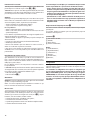
Commandes pendant l’appel
Augmenter volume
haut-parleur 123Augmenter sensibi-
lité du microphone
Diminuer volume
haut-parleur 456Diminuer sensibilité
microphone
789
Activation relais 1 * 0 #Activation relais 2
Fin de la conversation *
L’appel est terminé via la touche ‘0 ‘uniquement sur les appareils téléphoniques
du réseau xe.
Volume haut-parleur
Si pendant l’appel, l’interlocuteur n’entend pas la voix au bon volume; il est pos-
sible d’augmenter, en appuyant sur la touche ‘1’, ou de diminuer, en appuyant
sur la touche ‘4’, le volume du haut-parleur.
Sensibilité microphone
Si vous n’entendez pas correctement la voix de l’interlocuteur devant le poste
d’interphone, vous pouvez intervenir en appuyant sur la touche ‘3 ‘pour aug-
menter ou en appuyant sur la touche ‘6’ pour diminuer la sensibilité du micro-
phone.
Activation relais
Les deux relais permettent de piloter l’ouverture d’un portail ou d’une grille au-
tomatisée. Cette opération peut être eectuée pendant l’appel en appuyant sur
la touche pour activer le premier relais, ou bien en appuyant sur la touche
pour activer le deuxième relais.
REMARQUE : les deux relais ne peuvent pas supporter des tensions supé-
rieures à 60V et des courants de charge supérieurs à 500 mA.
Interrompre la conversation
Cette fonction doit être obligatoirement utilisée lorsque notre dispositif d’in-
terphone GSM contacte un numéro de téléphone xe. Appuyer sur la touche ‘0’
pour arrêter la conversation.
REMARQUE : Si la touche ‘0’ n’est pas activée, la conversation reste ouverte
jusqu’au temps de TIMEOUT de l’interphone (voir paramètre ‘H’).
Seite wird geladen ...
Seite wird geladen ...
Seite wird geladen ...
Seite wird geladen ...
Seite wird geladen ...
Seite wird geladen ...
Seite wird geladen ...
Seite wird geladen ...
Seite wird geladen ...
Seite wird geladen ...
Seite wird geladen ...
Seite wird geladen ...
Seite wird geladen ...
Seite wird geladen ...
Seite wird geladen ...
Seite wird geladen ...
-
 1
1
-
 2
2
-
 3
3
-
 4
4
-
 5
5
-
 6
6
-
 7
7
-
 8
8
-
 9
9
-
 10
10
-
 11
11
-
 12
12
-
 13
13
-
 14
14
-
 15
15
-
 16
16
-
 17
17
-
 18
18
-
 19
19
-
 20
20
-
 21
21
-
 22
22
-
 23
23
-
 24
24
-
 25
25
-
 26
26
-
 27
27
-
 28
28
-
 29
29
-
 30
30
-
 31
31
-
 32
32
-
 33
33
-
 34
34
-
 35
35
-
 36
36


CAME TARGHA GSM VR Installationsanleitung
- Typ
- Installationsanleitung
in anderen Sprachen
- français: CAME TARGHA GSM VR Guide d'installation
- español: CAME TARGHA GSM VR Guía de instalación
- italiano: CAME TARGHA GSM VR Guida d'installazione
Verwandte Artikel
Andere Dokumente
-
 MCZ MczControl Installation and Use Manual
-
SWITEL M800 Bedienungsanleitung
-
Extraflame GSM Module Bedienungsanleitung
-
Doro HandleEasy 330 gsm Bedienungsanleitung
-
LG KG810.ASWSBK Benutzerhandbuch
-
SWITEL M350 Bedienungsanleitung
-
LG F3000.ACISBK Benutzerhandbuch
-
LG KG220.AVDHBK Benutzerhandbuch
-
LG C3380.ARUSBL Benutzerhandbuch
