
1
R. 10/22 850 840
SAMOA Industrial, S.A. · Pol. Ind. Porceyo, I-14 · Camino del Fontán, 831 · 33392 - Gijón - Spain · Tel.: +34 985 381 488 · www.samoaindustrial.com
2022_10_04-12:30
Parts and technical service guide
Guía de servicio técnico y recambio
Guide d’instructions et pièces de rechange
Bedienungsanleitung und Teileliste
Part No. / Cód. / Réf. / Art. Nr.:
502 XXX
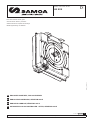
ENCLOSED HOSE REEL, RM-12CLX SERIES
ENROLLADOR CARENADO, SERIE RM-12CLX
ENROLEUR CARROSE, SÉRIE RM-12CLX
AUTOMATIK SCHLAUCHAUFROLLER - OFFEN, SERIE RM-12CLX
EN
FR
ES
DE

2850 840 R. 10/22
SAMOA Industrial, S.A. · Pol. Ind. Porceyo, I-14 · Camino del Fontán, 831 · 33392 - Gijón - Spain · Tel.: +34 985 381 488 · www.samoaindustrial.com
2022_10_04-12:30
EN
DESCRIPTION
Enclosed hose reel for air, cold & hot water, oil lubricants, grease, and other fluids depending on model.
Hose can be extended to the desired length and latched with the mechanism.
By pulling the hose, the latch is released and the hose is automatically rewound by means of a power spring.
WARNING
• This equipment is for professional use only.
• Do not allow the hose to recoil unattended.
• Ensure that pressure does not exceed maximum working pressure or temperature rating of lowest rated system component.
• Use fluids and solvents that are compatible with the equipments wetted parts.
• Release pressure inside the reel before servicing.
• Use protective guards or covers during use or maintenance.
• Fluids under pressure can cause serious injury.
• Do not alter or modify equipment.
• Keep clear of moving parts.
• The power spring is always under great tension. To reduce the risk of serious injury, do not attempt to replace or service the spring.
• To avoid damage the power spring, never exceed the maximum power spring turns, which are specified in this handbook.
!
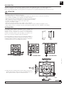
INSTALLATION
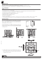
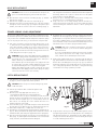
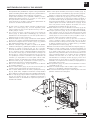
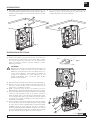
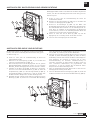
Hose reel can be installed directly onto a fixed surface or using a plate
(fig. A) or a pivoting bracket (fig. B). Be sure the mounting surface is
strong enough to support the weight of the reel, the fluid, and the stress
caused by pulls on the service hoses.
Several mounting positons are available to match the users needs. For a
proper and smooth operation, avoid the hose to bend with sharp radius
or angles. Hereafter you can see the recommended and most common
mounting positions: Fig. A Fig. B
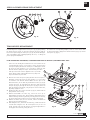
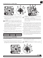
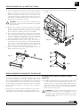
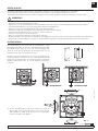
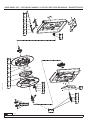
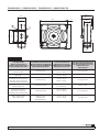
1. To take in place the hose reel, first assemble the base (1) (fig. 2) on
the desired hose reel flank. Then, use the sheet metal screws (2)
(fig. 2) to attach the base to the casing. Is possible to attach the base
in 3 different positions (fig. 2).
FLOOR WALL CEILING
Fig. 2
1
2

3
R. 10/22 850 840
SAMOA Industrial, S.A. · Pol. Ind. Porceyo, I-14 · Camino del Fontán, 831 · 33392 - Gijón - Spain · Tel.: +34 985 381 488 · www.samoaindustrial.com
2022_10_04-12:30
EN
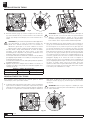
HOSE INSTALLATION
FIRST HOSE INSTALLATION:
1. For the first hose installation, be sure to securely anchor the hose reel
on a flat and stable surface. The power spring must be relaxed, in
such a way that the spool does not try to turn while the ratchet is
unlocked.
DANGER!
Handle the hose reel with care, wearing heavy leather gloves &
the appropriate sucurity elements. While turning the spool, the
power spring will gain force and speed, specially if the spool
starts to turn freely. Grab the spool firmly to avoid it to turn
freely, thus in this case, it could cause injuries. Keep clear of
moving parts during operation.
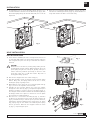
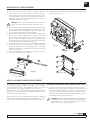
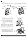
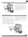
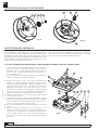
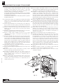
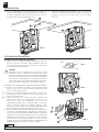
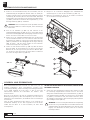
2. Place the hose stopper at the hose outlet end (fig. 5).
3. Take away the bolts (1) (fig. 6) which are used to hold the spring
fixation. Doing this, the spring fixation will be free to rotate,
avoiding the spring of getting tension.
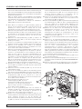
4. Disassemble the service lid (1) (fig. 7) loosening the plastic nuts (2)
(fig. 7). Tools are not required to loosen this nuts.
5. Introduce the hose end (the opposite one of the hose stopper)
through the rollers outlet (3) (fig. 7), and put it through the spool
window, to be able to conect it to the hose reel fitting (4) (fig. 7).
The casing has a wide window to facilitate the task. When tightening
the fittings, beware not to place too much stress over the plastic
spool, because it could be damaged.
6. Once the hose is connected to the fitting (4) (fig. 7), introduce
an Allen key (7 mm between faces) inside the brass hexagon (2)
(fig. 8), and turn this key to turn the spool in possitive direction,
following the indication stamped on the casing (4) (fig. 8). In this
way, step by step, the hose will be coiled and the power spring
will not get tension. When the hose stopper touches the rollers
(3) (fig. 7), stop turning the spool.
INSTALLATION
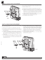
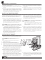
2. To suspend the hose reel on the mounting surface (2) (fig. 3), it is
recommended first to introduce in it two M10 bolts (1) (fig. 3), with
their heads slightly jutting out. Over this bolt heads, the reel can be
suspended.
Fig. 5
3. Once the reel is suspended, always holding it securely, proceed to
introduce the remaining two bolts (3) (fig. 4), which should be no
longer than 10mm to be able to screw them easily.
Fig. 4Fig. 3
1
2
3
Fig. 6
1
Fig. 7
1
2
5
4
3
!

4850 840 R. 10/22
SAMOA Industrial, S.A. · Pol. Ind. Porceyo, I-14 · Camino del Fontán, 831 · 33392 - Gijón - Spain · Tel.: +34 985 381 488 · www.samoaindustrial.com
2022_10_04-12:30
EN
HOSE INSTALLATION
!
CAUTION: Make sure to avoid the power spring to exceed the
19 maximum turns. If so, the service life and the spring power
will be decreased.
If you are in doubt about how many pre-tension turns to apply,
first, count the spool turns “N” to fully coil the desired hose.
Then, calculate 19·N = maximum pre-tension turns.
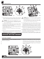
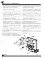
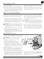
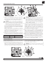
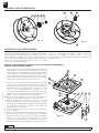
9. After applying the pre-tension turns, without releasing the tool (1)
(fig. 9) and grasping it firmly, introduce the bolts (3) (fig. 9). While
tightening these bolts, pay attention not to release the tool, because
this could cause injure. Once the first bolt is tighten, do not turn
again the tool, this stress could damage the Tensor piece (2) (fig. 9).
10. After tighten the 4 bolts (3) (fig. 9), release the tool (1) (fig. 9). Verify
if the hose reel is coiling properly with the desired force, coiling and
uncoiling several times. If necessary, adjust the spring tension
following the instructions shown in section “Spring load adjustment”.
11. Assemble the service lid (1) (fig. 7) using the plastic nuts (2) (fig. 7).
Do not apply too much torque, because you could damage the nuts
thread. No tools required for this operation.
12. Connect the inlet hose to the swivel. Make sure not to apply too much
torque to the swivel, use a flat-wrench if necessary to make counter-force.
TABLE 1. PRE-TENSION TURNS
Hose Lenght Pre-tension turns
1/2", 3/8", y 1/4" 30' & 50' 5
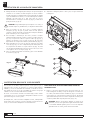
7. Take away the Allen key (1) (fig. 8), and replace it with a square key
(1) (fig. 9). Turning this key, the spring fixation (2) (fig. 9) will turn
(the spool will keep static) and the power spring will get tension.
WARNING: Extreme caution. While applying tension to the
power spring, it will get strong force. Grab firmly the key and the
hose reel, using heavy leather gloves. If the spool starts to turn
freely, it could cause injuries.
- Never allow the spool to turn freely. If it does, high speeds could be
reached. Hose reel parts could be damaged and you could be injured
if hit by the hose or any other moving part.
- Always grasp firmly, and with enough security, the spool and adjusting
tools while applying tension to the spring. The spring tension can
cause the tools to move violently.
- Attach the hose reel firmly on a flat stable surface during instalation/
maintenance.
8. Apply the pre-tension to the power spring as shown in Table 1, by
means turning the tool in possitive direction, following the indication
stamped on the casing (4) (fig. 8).
!
HOSE REPLACEMENT
To replace the aged hose for a new one with similar caracteristics,
follow the next procedure:
Fig. 8
1
2
3
4
5
Fig. 9
12 3
Fig. 10
2
1
3
4
5
1. With the hose reel firmly attached on a surface, uncoil all the hose
and latch the spool in the nearest position. For higher security, use
a tool which avoid the spool to turn freely. If not, it is recommended
to block de spool by introducing an Allen key 7 mm between faces
(1) (fig. 10) inside the brass hexagon (2) (fig. 10), through the
Tensor piece (3) (fig. 10).

5
R. 10/22 850 840
SAMOA Industrial, S.A. · Pol. Ind. Porceyo, I-14 · Camino del Fontán, 831 · 33392 - Gijón - Spain · Tel.: +34 985 381 488 · www.samoaindustrial.com
2022_10_04-12:30
EN
CAUTION: Beware not to free the latch because the spool can
get loose and start turning freely, which could cause injure.
2. Disconnect the old hose from the reel fitting (4) (fig. 7), and take
away the hose stopper.
3. Place the hose stopper at the new hose outlet end (fig. 5).
4. Introduce the new hose end (the opposite one of the hose stopper)
through the rollers outlet (3) (fig. 7), and put it through the spool
window, to be able to conect it to the hose reel fitting (4) (fig. 7).
HOSE REPLACEMENT
The casing has a wide window to facilitate the task. When tightening
the fittings, beware not to place too much stress over the plastic
spool, because it could be damaged.
5. Release the spool, unlatching and removing all the security tools,
and let the hose to coil gently between your hands.
6. Verify if the hose reel is coiling properly with the desired force,
coiling and uncoiling several times. If necessary, adjust the spring
tension following the instructions shown in section “Spring load
adjustment”.
POWER SPRING LOAD ADJUSTMENT
The hose reels supplied with hose, have setted as a standar pre-tension
the maximum pre-tension available, which match with shown in Table
1. If you don´t feel confortable with this and prefer to adjust the spring
force to suit your personal choice, you can follow the next procedure:
1. First of all is necessary to remove the power spring tension. To do
so, with all the hose coiled and the hose stopper contacting with the
roller outlet, introduce a square key (1) (fig. 9) in the Tensor piece
(2) (fig. 9), and loosen the bolts (3) (fig. 9). Do not turn the tool (1)
(fig. 9) until all the bolts have been taken away, because the stress
could damage the Tensor piece (3) (fig. 10).
WARNING: Extreme caution while applying tension adjustments
to the power spring, because it has strong force. Grab firmly the
key and the hose reel, using heavy leather gloves. If the spool
starts to turn freely, it could cause injuries.
- Never allow the spool to turn freely. If it does, high speeds could
be reached. Hose reel parts could be damaged, and you could
be injured if hitted by the hose or any other moving part.
- Always grasp firmly and with enough security the spool and
adjusting tools while applying tension to the spring. The spring
tension can cause the tools to move violently.
!
2. By turning the tool in negative direction, following the indication
stamped on the casing (4) (fig. 8), the power spring will loose force.
By turning the tool in possitive direction, the power spring will gain
force. Add or subtract turns as you need allways having in mind to
leave a minimum of 2 pre-tension turns and a maximum pre-tension
turn which avoid to exceed the spring total allowed turns.
CAUTION: Make sure to avoid the power spring to exceed the
19 maximum turns. If so, the service life and the spring power
will be decreased.
If you are in doubt about how many pre-tension turns to apply,
first, count the spool turns “N” to fully coil the desired hose.
Then, calculate 19-N = maximum pre-tension turns.
3. Finally, while grasping firmly the tool, introduce again the bolts (3)
(fig. 9). Remember not to turn the tool when the bolts are in place,
because this could damage the Tensor piece (3) (fig. 10). When all
the bolts are tightened, you can take away the tool. Verify if the hose
reel is coiling properly with the desired force, coiling and uncoiling
several times. If necessary, repeat the procedure.
!
!
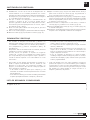
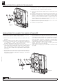
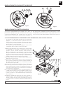
LATCH REPLACEMENT
1. Take apart the service lid (2) (fig. 11) loosening the plastic nuts
(1) (fig. 11). No tools required to do this operation.
2. Turn the spool until the latch is visible through the wide
service window.
3. Block the spool using appropiate tools. If not, it is
recommended to block the spool using an Allen key
7 mm between faces (1) (fig. 8) introducing it inside the brass
hexagon (2) (fig. 8), through the Tensor piece (3) (fig. 8). You can
also move the hose stopper (fig. 5) to a new position, where the
latch can be seen through the service window when the hose
stopper touches the roller outlet.
4. Loosen the bolt (3) (fig. 11) and take away the reinforcement metal
sheet (4) (fig. 11), the latch (5) (fig. 11), and the spring (6) (fig. 11).
5. Clean all the components, or replace then for a new ones.
6. Assemble the new latch and the sprig through the guiding axis (7)
(fig. 11), having in mind that the spring arms side must be oriented
towards the latch, and leaving the spigot between the spring arms.
7. Place the reinforcement metal sheet (4) (fig. 11) and introduce the
bolt (3) (fig. 11). When tighten the bolt beware not to exceed 4 Nm
torque, otherwise, the bolt thread can be damaged.
CAUTION: Beware the spool not to start turning freely, which
could cause injure.
!
Fig. 11
1 2 3 4 5 6
7
8. Verify the latch is moving correctly and assemble again the service
lid, tightening the plastic nuts carefully (beware not to damage the
nuts thread). Hold the hose and unlatch the spool taking away the
security tools which are blocking its movement. Gently let the spool
to coil the remaining uncoiled hose.

6850 840 R. 10/22
SAMOA Industrial, S.A. · Pol. Ind. Porceyo, I-14 · Camino del Fontán, 831 · 33392 - Gijón - Spain · Tel.: +34 985 381 488 · www.samoaindustrial.com
2022_10_04-12:30
EN
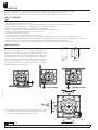
SWIVEL & SEALING RINGS REPLACEMENT
It is no necessary to disassemble the casing for easily replace the swivel.
Follow the next steps to do it:
1. Make sure the hose stopper is in contact with the rollers outlet.
2. Take apart the circlip (1) (fig. 12) and remove the swivel (2) (fig. 12).
3. Replace the sealing rings (3) (fig. 12). For the medium & high
pressure hose reels, the sealing rings are located on the swivel. For
low pressure hose reels, the sealing rings are located on the shaft. If
you also need to replace the swivel, disconnect the inlet hose from
it and connect the hose again to the new swivel.
4. Apply a bit of grease to the swivel and the shaft (4) (fig. 12) before
introducing the swivel carefully through the shaft.
5. Place again the circlip on the shaft.
SHAFT & SEALING RINGS REPLACEMENT
It is no necessary to disassemble the casing for easily replace the shaft.
Follow the next steps to do it:
1. Make sure the hose stopper is in contact with the rollers outlet.
2. Take apart the circlip (1) (fig. 13) and remove the swivel (3) (fig. 13).
3. Swivel sealing rings, as shown at previous section “swivel & sealing
rings replacement”.
4. Unscrew the shaft (4) (fig. 13). For doing this, it is needed to do
counterforce by introducing an Allen key 7mm between faces (1)
(fig. 8) inside the brass hexagon (2) (fig. 8), through the Tensor
piece (3) (fig. 8). Avoid to transmit stress to other hose reel
components.
5. Once the shaft has been taken apart, you will be able to reach the
inner sealing ring (5) (fig. 13). Replace it if necessary. This sealing
ring is used in all the hose reels models, located inside the inner
rotating part (6) (fig. 13).
6. Introduce carefully the shaft inside the inner rotating part (6) (fig. 13),
through the inner sealing ring (5) (fig. 13), be careful not to damage
it with the shaft thread. It is recommended to clean the threads and
apply a medium strength threadlocker in this threaded coupling. For
tighten the shaft, again use the Allen key to make counterforce,
avoiding the stress to transmit to other hose reel components.
7. Apply a bit of grease to the swivel and to the shaft, and introduce
the swivel through the shaft carefully.
8. Finally, place again the circlip (1) (fig. 13) on the shaft, and take
apart the Allen key (1) (fig. 8).
Fig. 12
1
2
34
Fig. 13
12
3
4 5 6

7
R. 10/22 850 840
SAMOA Industrial, S.A. · Pol. Ind. Porceyo, I-14 · Camino del Fontán, 831 · 33392 - Gijón - Spain · Tel.: +34 985 381 488 · www.samoaindustrial.com
2022_10_04-12:30
EN
1. Uncoil a short leght of the hose, only to avoid the hose stopper to
contact with the roller outlet. Make sure to latch the spool. For
higher security, use a tool which avoid the spool to turn freely. If not,
it is recommended to block de spool by introducing an Allen key 7
mm between faces (1) (fig. 8) inside the brass hexagon (2) (fig. 8),
through the Tensor piece (3) (fig. 8).
CAUTION: Beware not to free the latch because the spool can
get loose and start turning freely, which could cause injure.
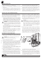
2. Loosen the bolts (1) (fig. 14) and take away the roller outlet assembly
(2) (fig. 14) which can be disassembled in a single piece. The roller
outlet assembly can be disassembled into pieces for cleaning. Also
you can replace it by a new roller outlet assembly.
3. Once the roller outlet assembly has been cleaned or replaced by a
new one, it is necessary to assemble all its components. For doing
this, first of all you should place the long rollers (1) (fig. 15) in its
position over the roller supports (2) (fig. 15), and go through this
assembly with the long axles (3) (fig. 15). This way, you should have
two equal components pre-assembled (4) (fig. 15).
4. Now take the short axles (2) (fig. 16) to go through the short rollers
(1) (fig. 16) and use these components to join both preassembled
components made in the previous step (4) (fig. 16). For doing this,
manually exert pressure to introduce the short axles pins, in the long
axles holes (3) (fig. 16).
5. Take the assembled roller outlet and put it in place over the hose
reel, and fix it using the bolts (1) (fig. 14).
ROLLER OUTLET REPLACEMENT
SPOOL & POWER SPRING REPLACEMENT
This reel model uses a power spring to coil the hose. This power spring
no requires maintenance, and with a reasonable use, it is unusual a
power spring failure. Because of this, probably it would be not necessary
you to replace the power spring during the hose reel service life.
The power spring is a component subjected to high loads, even when it
is relaxed, so it is recommended not no manipulate or replace the power
spring to avoid risk of serious injuries.
In any case, if it is necessary to replace the power spring, it is available a
spool kit, which contains the power spring confined inside. This way, it
would not be necessary to manipulate the power spring directly.
TO REPLACE THE HOSE REEL SPOOL, FOLLOW THE NEXT STEPS:
1. First of all is necessary to remove the power spring tension. To do so,
with all the hose coiled and the hose stopper contacting with the
roller outlet, introduce a square key (1) (fig. 9) in the Tensor piece
(2) (fig. 9), and loosen the bolts (3) (fig. 9). Do not turn the tool (1)
(fig. 9) until all the bolts have been taken away, because the stress
could damage the Tensor piece (3) (fig. 10).
WARNING: Extreme caution while applying tension adjustments
to the power spring, because it has strong force. Grab firmly the
key and the hose reel, using heavy leather gloves. If the spool
starts to turn freely, it could cause injuries.
Fig. 16
1
2
3
4
Fig. 14
1
2
1
Fig. 15
1
2
3
4
!
6. Holding the hose, unlatch the spool removing all the tools used, and
gently let the hose to coil.
!

8850 840 R. 10/22
SAMOA Industrial, S.A. · Pol. Ind. Porceyo, I-14 · Camino del Fontán, 831 · 33392 - Gijón - Spain · Tel.: +34 985 381 488 · www.samoaindustrial.com
2022_10_04-12:30
EN
SPOOL & POWER SPRING REPLACEMENT
- Never allow the spool to turn freely. If it does, high speeds could be
reached. Hose reel parts could be damaged and you could be
injured if hitted by the hose or any other moving part.
- Always grasp firmly, and with enough security, the spool and
adjusting tools while applying tension to the spring. The spring
tension can cause the tools to move violently
2. By turning the tool in negative direction, following the indication stamped
on the casing (4) (fig. 10), the power spring will loose force. Make sure the
power spring has no tension and the spool don´t tend to turn.
3. With the power spring relaxed, and the spring fixation without the
bolts (3) (fig. 9), take away the square key (1) (fig. 9) and uncoil
manually all the hose. In this way, you will be able to uncoil the hose
avoiding the power spring to get tension.
4. Take away the service lid (1) (fig. 7), by loosening the plastic nuts (2)
(fig. 7). No tools are required for this operation.
5. Disconnect the hose from the reel fitting (4) (fig. 7), and keep it to
be able to install it again later on the new spool.
6. Disassemble the latch as show in “latch replacemen” chapter (point 4),
and keep it to be able to install it again later on the new spool.
7. Disassemble the set shaft-swivel (1) (fig. 17). It is not necessary to
disassemble the swivel from the shaft. Use a flat-wrench over the
shaft hexagon, and be sure to do counterforce by introducing an
Allen key 7 mm between faces (1) (fig. 10) inside the brass hexagon
(2) (fig. 10), through the Tensor piece (3) (fig. 10). Avoid to transmit
stress to other hose reel components and don´t aplly lever with the
flat-wrench over the swivel. keep it to be able to install again later
on the new spool.
8. Take apart the base (2) (fig. 17) loosening the bolts (3) (fig. 17).
Keep the base to be able to install again later on the new spool.
9. Loosen the two bolts (4) (fig. 17) which hold one side of the roller
outlet. Keep these bolts to be able to install again later.
10. Loosen the four casing bolts (5) (fig. 16). At this point, you can take
apart both casing sides (6) (fig. 16). Keep the casing to be able to
assemble it again later.
11. With the spool assembly outside the casing, the Tensor piece (1)
(fig. 18) is released, take it apart without disassembly its inner
metalic sheet. Keep it to be able to install again later.
12. Move away the circlip (2) (fig. 18) which keeps the spring fixation
on the spool shaft (4) (fig. 18). Take apart the spring fixation (3)
(fig. 18), without disassembling the bearing located inside it.
Keep all the components to be able to reassembly later.
13. At the opposite spool side, loosen the bolts (1) (fig. 19) used to fix
the brass shaft (2) (fig. 19) to the spool (3) (fig. 19). Keep all the
components to be able to reassembly later.
14. Replace the spool (3) (fig. 19) by a new one, and procced to
reassemble again all the components in reverse order. Begin
assembling the spool brass shaft (2) (fig. 19) tightening the bolts (1)
(fig. 19). To avoid spool damage, do not apply a torque more than
4Nm while tightening these bolts. To be able to assemble the spool
shaft (2) (fig. 19) in the correct position, make sure to assemble it
with the fitting pointing to the spool window (4) (fig. 19).
15. Mount the spring fixation (with its bearing inside) (3) (fig. 18)
through the brass shaft, and fasten it in its position using the circlip
(2) (fig. 18).
16. Place the Tensor piece (1) (fig. 18) (with its metal sheet assembled
inside) over the spring fixation (3) (fig. 18). This Tensor piece will be
loose, so hold it with your hand while takind the spool assembly
inside the casing (the one with no service window). Make sure the
Tensor piece fits in the casing central hole.
17. Assemble the other casing side (the one with the service window),
fitting its central hole on the brass shaft. For a correct assembly
position, the wings which hold the roller outlet, must be aligned.
Join both casing sides by tightening the bolts (5) (fig. 17).
18. Tighten the two roller outlet bolts (4) (fig. 17).
19. Place the shaft-swivel assembly (1) (fig. 17). For doing this, introduce
carefully the shaft through the casing bearing, be careful not to
damage the inner sealing ring with the shaft thread. It is
recommended to clean the threads and apply a medium strength
threadlocker in this threaded coupling. For tighten the shaft, it is
needed to do counterforce by introducing an Allen key 7 mm
between faces (1) (fig. 8) inside the brass hexagon (2) (fig. 8),
through the Tensor piece (3) (fig. 8). Avoid to transmit stress to
other hose reel components.
20. Place the base (2) (fig. 17) in position on the casing, using the sheet
metal screws (3) (fig. 17).
21. Mount the latch assembly on the spool, as shown in chapter “Latch
replacement” (points 6 & 7).
22. Proceed to assembly the hose as shown in chapter “Hose installation”
(points 5 to 12).
Fig. 17
1
2
3
4
5
6
3
5

9
R. 10/22 850 840
SAMOA Industrial, S.A. · Pol. Ind. Porceyo, I-14 · Camino del Fontán, 831 · 33392 - Gijón - Spain · Tel.: +34 985 381 488 · www.samoaindustrial.com
2022_10_04-12:30
EN
SPOOL & POWER SPRING REPLACEMENT
TENSOR PIECE REPLACEMENT
- If the hose has already been installed in the reel and also has its
corresponding pre-tension, is necessary to remove the pre-tension
to the power spring. Because the Tensor piece is damaged, it cannot
be used to do this operation, so it is necessary to follow the next
alternate method. Jump onto step 1 and follow the procedure.
- If the pre-tension has not been applied to the reel, and the
power spring remains relaxed without tension, jump onto
step 7 and follow the procedure.
1. Remove the load to the power spring. Because the Tensor piece is
damaged, it cannot be used to do this operation, so it is necessary
to follow the next alternate method: Make sure the spool is not
latched and then, use an Allen key 7mm between faces (1) (fig. 8)
to block the spool, by introducing the Allen key inside the brass
hexagon (2) (fig. 8), through the Tensor piece (3) (fig. 8). Once the
Allen key has been introduced, verify the spool do not tend to turn,
by pulling slightly the hose.
2. Holding the Allen key, release the bolts (5) (fig. 8) which hold the
spring fixation to the casing.
3. Whitout disassemble the Allen key, uncoil the hose up to
approximately six meters (20’). Notice that the spring fixation piece
and the Allen key will turn together. By uncoiling the hose this way,
the power spring will not gain more tension than it already has.
4. With the six meters (20’) of hose uncoiled, return to assemble the
bolts (5) (fig. 8) tightening them.
5. Grab firmly the hose, and release the Allen key, in that moment the
reel will start coiling the hose. Do not drop the hose, let it to coil
gently. You will notice how the spring is loosing strenght while it is
loosing pretension turns by coiling the hose.
If accidentaly stress is applied to the Tensor piece (3) (fig. 8) by turning
the square wrench (1) (fig. 9), when the four bolts (5) (fig. 8) had not
been removed previously, the Tensor piece (7) (fig. 20) can be damaged.
This could happen while installing/replacing the hose, or during the
power spring load adjustment.
As noted in the corresponding chapters, assure to remove all the bolts
(5) (fig. 8) previously to apply stress with the wrench (1) (fig. 9) over the
tensor piece (3) (fig. 8).
IF THE TENSOR PIECE IS DAMAGED, IT WOULD BE NECESSARY TO REPLACE IT, FOLLOWING NEXT STEPS:
Fig. 18
12345
1
2
3
4
Fig. 19
Fig. 20
1
23
6
8
9
310 5 4
3
7
5

10 850 840 R. 10/22
SAMOA Industrial, S.A. · Pol. Ind. Porceyo, I-14 · Camino del Fontán, 831 · 33392 - Gijón - Spain · Tel.: +34 985 381 488 · www.samoaindustrial.com
2022_10_04-12:30
EN
DISPOSAL AND RECYCLING INFORMATION
• This product has been developed and manufactured with high
quality materials and components which mostly can be recycled
and/or reused, such as metals: (brass, aluminum, and steel, mainly)
and also thermoplastic polymers: (PP and HIPS, mainly).
This product must be disposed of separately from ordinary household
wastes at its end of life. Please dispose of this product at your local
collection point or recycling centre. Do this to make sure that the
product is recycled in an environmental friendly way, and help to
protect the environment in which we all live.
• This product has been designed to minimize as far as possible its
environmental impact. For that propose, different strategies has
been implemented in addition to using recyclable and not dangerous
materials. Some of these strategies are shown as follows:
• The quantity of components has been reduced, and also the variety
of different raw materials needed to manufacture the product.
The overall dimensions and the weight have been reduced to
minimize the environment impact during transport and storage.
As far as possible, already existing parts have been used to reduce
the quantity of new components to be created.
The different components have been tested for maximum toughness
and durability.
These hose reels are powered by an autonomous spring. Not batteries
are used, and no electrical consumption or other energy source is
needed. This product has no electrical or electronic components.
By using hose reels at the working place, the hoses working life is
increased. Also the fluids handling becomes cleaner and safer,
avoiding spills and improving the healthy and security at the
working place.
• All this measures, among other ones, are oriented to achieve a more
environment-friendly product, because they contribute to reduce
resources needed throughout the product life cycle, such as:
manufacturing, assembly, maintenance, transport, and storage; and
also the generated waste is reduced when the product reach its
lifetime end.
TENSOR PIECE REPLACEMENT
6. Probably the power spring will stop pulling the hose before completely
coiled the 6 meters (20’) previously uncoiled. This is a good sign
about we are making properly the procedure. In any case, be careful
not letting the hose end to introduce inside the reel casing.
7. Avoid the hose end to introduce inside the reel casing, and make
sure the spring has lost all its load and it remains relaxed. The spool
must not tend to turn. If still the spring has remaining load, repeat
the procedure since step 1.
8. Now it is necessary to take away the casing side, for doing this,
proceed to take apart the bolts (1) (fig. 20).
9. Take apart the two bolts (2) (fig. 20) located in the roller outlet side.
10. Disassemble the base (4) (fig. 20) by loosening the bolts (5) (fig. 20).
11. Loosen the bolts (3) (fig. 20) which join both casing sides. Now you
can take apart the casing side (6) (fig. 20) been able to access the
Tensor piece (7 & 8) (fig. 20).
12. Replace the tensor piece (7) (fig. 20) and its inner metal sheet (8)
(fig. 20) for a new ones. Make sure to assemble the inner metal sheet
inside the plastic tensor piece, before placing the assembly on the
spring fixation (9) (fig. 20).
13. Assemble again all the components in reverse order, by placing the
unassembled casing side (6) (fig. 20) and fixing it to the other casing
side by tightening the bolts (3) (fig. 20).
14. Assemble the base again (4 & 5) (fig. 20), and the roller outlet bolts
(2) (fig. 20).
15. Finally, apply load to de power spring following the steps shown at
point 6 to 10 on chapter “hose installation”.
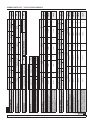
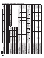
DIMENSIONS AND SPARE PARTS LIST
See pages: 38, 40, 41.

11
R. 10/22 850 840
SAMOA Industrial, S.A. · Pol. Ind. Porceyo, I-14 · Camino del Fontán, 831 · 33392 - Gijón - Spain · Tel.: +34 985 381 488 · www.samoaindustrial.com
2022_10_04-12:30
ES
DESCRIPCIÓN
Enrollador de manguera carenado para aire, agua fría o caliente, aceites lubricantes, grasa, y otros fluidos según modelos.
Al tirar de la manguera, ésta se desenrolla pudiendo bloquearse a la longitud deseada por acción de un trinquete.
Para recoger la manguera, basta con tirar ligeramente de ella para que sea recogida automáticamente por acción de un resorte.
ATENCIÓN
• Este equipo es para uso profesional.
• Acompañe siempre la recogida de la manguera.
• No sobrepase la presión o el rango de temperatura de trabajo del componente menos resistente de la instalación.
• Use con fluidos compatibles con los materiales de las partes húmedas.
• Elimine la presión interior del fluido durante las operaciones de mantenimiento.
• Utilice dispositivos de protección durante el uso y mantenimiento del equipo.
• Los fluidos sometidos a presión, pueden causar graves daños.
• No altere ni modifique el equipo.
• Manténgase alejado de las partes móviles durante su funcionamiento.
• El resorte está siempre bajo tensión. Para reducir el riesgo de daño, no intente cambiar ni manipular el resorte.
• Para no dañar el resorte, no sobrepase nunca las vueltas máximas de trabajo del resorte, indicadas en este manual.
!
INSTALACIÓN
El enrollador puede instalarse directamente sobre la superficie de
montaje, una base de fijación (fig. A) o un soporte pivotante (fig. B).
Asegúrese de que la superficie de montaje es lo suficientemente
resistente como para soportar el peso del equipo, de los fluidos en su
interior, y de los esfuerzos realizados al tirar de la manguera.
El enrollador dispone de varias posiciones de montaje para adaptarse a
las necesidades del usuario. Para un adecuado funcionamiento, evite que
la manguera adopte curvaturas o ángulos muy cerrados. A continuación
se muestran las posiciones recomendadas mas comunes: Fig. A Fig. B
1. Para posicionar el enrollador, primero monte la base (1) (fig. 2) en el
lateral deseado. Para ello, utilice los tornillos roscachapa (2) (fig. 2). La
base se puede montar en 3 posiciones diferentes (fig. 2).
POSICIÓN SUELO POSICIÓN PARED POSICIÓN TECHO
Fig. 2
1
2

12 850 840 R. 10/22
SAMOA Industrial, S.A. · Pol. Ind. Porceyo, I-14 · Camino del Fontán, 831 · 33392 - Gijón - Spain · Tel.: +34 985 381 488 · www.samoaindustrial.com
2022_10_04-12:30
ES
Fig. 3
1
2
Fig. 4
3
INSTALACIÓN DE LA MANGUERA
INSTALACIÓN DE LA MANGUERA POR PRIMERA VEZ:
1. Para instalar la manguera por primera vez, asegúrese de que el
enrollador está bien sujeto sobre una superficie plana y estable. El
resorte no debe tener tensión, de tal modo que con el trinquete
liberado, el tambor no tienda a girar libremente por si solo.
¡PELIGRO!:
Maneje el enrollador con cuidado usando guantes gruesos y los
elementos de seguridad necesarios. Al girar el tambor, el resorte
puede llegar a coger gran fuerza y velocidad, especialmente si se
deja girar libremente. Sujete firmemente el tambor del enrollador,
evitando que gire libremente, pues en dicho caso podría causar
daños. Manténgase alejado de las partes móviles durante su
funcionamiento.
2. Monte el tope de manguera en el extremo de salida de la manguera
(fig. 5).
3. Retire los tornillos (1) (fig. 6) que sujetan la fijación resorte, para que
ésta quede libre y el resorte no coja tensión aunque se gire el tambor.
4. Desmonte la tapa se servicio (1) (fig. 7) aflojando las tuercas plásticas
(2) (fig. 7). No se requiere de herramienta para aflojar estas tuercas.
5. Introduzca el extremo de la manguera (el extremo opuesto al tope
de manguera) por la salida de manguera (3) (fig. 7), y métala a
través de la ventana del disco, para conectarla al racor del enrollador
(4) (fig. 7). Una amplia ventana en la carena facilitará esta tarea.
Tenga cuidado al apretar las roscas de no hacer excesiva palanca
sobre el disco plástico, el cual podría dañarse.
6. Una vez la manguera esta conectada al racor (4) (fig. 7),
introducir una llave allen (1) (fig. 8) de 7 mm entre caras en el
hexágono de latón (2) (fig. 8), y con esta llave, girar el tambor en
sentido positivo siguiendo la indicación (4) (fig. 8) presente en la
carcasa. De este modo se irá recogiendo la manguera poco a
poco dentro del tambor sin que el resorte coja tensión. Cuando
el tope de manguera llegue a contactar con los rodillos de la
salida de manguera (3) (fig. 7), deje de girar el tambor.
INSTALACIÓN
2. Para instalar el enrollador sobre la superficie de montaje (2) (fig. 3),
primero se recomienda introducir 2 tornillos de M10 (1) (fig. 3)
sobre la superficie, dejando sobresalir las cabezas de estos sobre las
que se colgará el enrollador.
Fig. 5
3. Una vez el enrollador esté colgado, sin dejar de sujetarlo, introducir
los otros 2 tornillos restantes (3) (fig. 4), los cuales no deberán tener
una longitud superior a 10 mm para poder introducirlos con
facilidad.
Fig. 6
1
Fig. 7
1
2
5
4
3
!

13
R. 10/22 850 840
SAMOA Industrial, S.A. · Pol. Ind. Porceyo, I-14 · Camino del Fontán, 831 · 33392 - Gijón - Spain · Tel.: +34 985 381 488 · www.samoaindustrial.com
2022_10_04-12:30
ES
INSTALACIÓN DE LA MANGUERA
!
ATENCIÓN: Asegúrese de que el resorte nunca alcanza más de
19 vueltas totales. Si se sobrepasan, la vida útil y la fuerza de
recogida del mismo, se verán reducidas.
Si tuviese dudas de cuanta pretensión aplicar, primero cuente el
número de vueltas del disco necesarias “N” para recoger
totalmente la manguera a utilizar. Después reste 19-N = máxima
pretensión disponible.
9. Tras aplicar las vueltas de pretensión, sin dejar de sujetar la llave (1)
(fig. 9) y agarrándola firmemente, proceder a introducir los tornillos
(3) (fig. 9). Durante el apretado de estos tornillos prestar atención a
que no se escape la llave, pues existe riesgo de lesión. Una vez está
introducido el primer tornillo, no intentar girar de nuevo la llave,
pues el esfuerzo podría dañar la pieza pretensora (2) (fig. 9).
10. Tras apretar los 4 tornillos (3) (fig. 9), retire la llave (1) (fig. 9).
Compruebe que el enrollador recoge la manguera adecuadamente,
extrayéndola y recogiéndola varias veces. Si fuese necesario, ajuste la
tensión del resorte siguiendo las instrucciones del apartado “Ajuste
de la tensión del resorte”.
11. Coloque de nuevo la tapa de servicio (1) (fig. 7) utilizando las tuercas
plásticas (2) (fig. 7). No aplique excesivo par a las tuercas para evitar
pasar la rosca. No se requieren herramientas para esta operación.
12. Conecte la manguera de acometida a la rótula. Procure no ejercer
excesivo par torsor a la rótula, para ello utilice una llave plana si fuese
necesario, para contrarestar el par.
TABLA 1. VUELTAS DE PRETENSIÓN
Manguera Longitud Vueltas de pretensión
1/2", 3/8", y 1/4" 30' & 50' 5
7. Retire la llave Allen (1) (fig. 8), y en su lugar introduzca una llave
cuadrada (1) (fig. 9). Al girar esta llave, se estará girando la fijación
resorte (2) (fig. 9) (el disco permanecerá estático) y el resorte
empezará a coger tensión.
ATENCIÓN: Extreme la precaución. Durante la aplicación de la
pretensión, el resorte empezara a coger gran fuerza. Agarre
firmemente la llave y el enrollador utilizando guantes gruesos. Si
el resorte empieza a girar libremente sin control, puede causar
serias heridas.
- Nunca permita al disco girar libremente. Si gira sin control, puede alcanzar
grandes velocidades, pudiendo dañar componentes y causar heridas si es
alcanzado por la manguera o algún componente en movimiento.
- Siempre sujete firmemente y con seguridad el tambor y las llaves
utilizadas para aplicar pretensión. Si se sueltan, el resorte puede
hacer que las llaves se muevan violentamente.
- Sujete firmemente el enrollador en una superficie plana durante las
operaciones de instalación/mantenimiento.
8. Aplicar la pretensión indicada en la siguiente Tabla 1, girando la llave
en sentido positivo siguiendo la indicación que aparece en la carena
(4) (fig. 8):
!
Para sustituir la vieja manguera por otra nueva de iguales características,
seguir el siguiente procedimiento:
1. Con el enrollador firmemente sujeto a una superficie, extraer toda la
manguera y dejar el tambor bloqueado por el trinquete en la
posición más cercana. Para mayor seguridad, utilice una herramienta
que impida el giro del tambor. En su defecto, se recomienda
!
Fig. 8
1
2
3
4
5
Fig. 9
12 3
Fig. 10
2
1
3
4
5
SUSTITUCIÓN DE LA MANGUERA
bloquear el tambor utilizando una llave Allen de 7 mm entre caras
(1) (fig. 10) introduciéndola en el hexágono de latón (2) (fig. 10), a
través de la pieza pretensora (3) (fig. 10).
ATENCIÓN: Tenga cuidado para que el trinquete no se suelte y el
enrollador empiece a girar libremente, lo cual puede causar heridas.

14 850 840 R. 10/22
SAMOA Industrial, S.A. · Pol. Ind. Porceyo, I-14 · Camino del Fontán, 831 · 33392 - Gijón - Spain · Tel.: +34 985 381 488 · www.samoaindustrial.com
2022_10_04-12:30
ES
2. Desconectar la manguera del racor del enrollador (4) (fig. 7), y
desmontar el tope de manguera.
3. Colocar el tope de manguera en el extremo de salida de la nueva
manguera.
4. Introduzca el extremo de la nueva manguera por la salida de manguera
(3) (fig. 7), y métala a través de la ventana del disco, para conectarla al
racor del enrollador (4) (fig. 7). Una amplia ventana en la carena
facilitará esta tarea. Tenga cuidado al apretar las roscas de no hacer
excesiva palanca sobre el disco plástico, el cual podría dañarse.
SUSTITUCIÓN DE LA MANGUERA
5. Libere el disco eliminando todos los elementos de seguridad y el
trinquete, y deje recoger la manguera dejándola deslizar suavemente
entre las manos.
6. Compruebe que el enrollador recoge la manguera adecuadamente,
extrayéndola y recogiéndola varias veces. Si fuese necesario, ajuste
la tensión del resorte siguiendo las instrucciones del apartado
“Ajuste de la tensión del resorte”.
AJUSTE DE LA TENSIÓN DEL RESORTE
Los enrolladores suministrados con manguera, llevan de manera
estándar la máxima pretensión disponible, que es la que se indica en la
Tabla 1. Si no le resultara confortable y prefiere ajustar la fuerza de
recogida a su gusto, puede seguir el siguiente procedimiento:
1. Primero es necesario eliminar la tensión del resorte. Para ello, con toda
la manguera enrollada y el tope de manguera en contacto con los
rodillos, introduzca una llave cuadrada (1) (fig. 9) en la fijación resorte
(2) (fig. 9), y desenrosque los tornillos (3) (fig. 9). No intentar girar la
llave (1) (fig. 9) hasta que todos los tornillos hayan sido retirados,
pues el esfuerzo podría dañar la pieza pretensora (3) (fig. 10).
ATENCIÓN: Extreme la precaución. Durante los ajustes de la
pretensión, el resorte tiene gran fuerza. Agarre firmemente la llave
y el enrollador utilizando guantes gruesos. Si el resorte empieza a
girar libremente sin control, puede causar serias heridas.
- Nunca permita al disco girar libremente. Si gira sin control, puede alcanzar
grandes velocidades, pudiendo dañar componentes y causar heridas si es
alcanzado por la manguera o algún componente en movimiento.
- Siempre sujete firmemente y con seguridad el tambor y las llaves
utilizadas para aplicar pretensión. Si se sueltan, el resorte puede
hacer que las llaves se muevan violentamente.
- Sujete firmemente el enrollador en una superficie plana durante las
operaciones de instalación/mantenimiento.
!
2. Al girar la llave en sentido negativo siguiendo la indicación que
aparece en la carena (4) (fig. 8), el resorte empezará a perder
tensión. Al girar la llave en sentido positivo el resorte ganará tensión.
Reste o añada vueltas según convenga teniendo siempre en cuenta
en dejar un mínimo de 2 vueltas de pre-tensión y un máximo que
evite sobrepasar las vuelas totales del resorte.
ATENCIÓN: Asegúrese de que el resorte nunca alcanza más de
19 vueltas totales. Si se sobrepasan, la vida útil y la fuerza de
recogida del mismo, se verán reducidas.
Si tuviese dudas de cuanta pretensión aplicar, primero cuente el
número de vueltas del disco necesarias “N” para recoger
totalmente la manguera a utilizar. Después reste 19-N = máxima
pretensión disponible.
3. Finalmente, y sin dejar de sujetar firmemente la llave, introduzca de
nuevo los tornillos (3) (fig. 9). Recuerde no intentar girar la llave
cuando los tornillos ya están colocados, pues el esfuerzo podría
dañar la pieza pretensora (3) (fig. 10). Cuando todos los tornillos
estén apretados, retirar la llave. Compruebe que el enrollador recoge
la manguera adecuadamente, extrayéndola y recogiéndola varias
veces. Si fuese necesario, repita la operación.
!
SUSTITUCIÓN DEL TRINQUETE
1. Desmonte la tapa de servicio (2) (fig. 11) aflojando las tuercas
plásticas (1) (fig. 11). No se requiere de herramienta para realizarlo.
2. Gire el tambor hasta que el trinquete quede visible por la
amplia ventana de servicio.
3. Bloquee el tambor utilizando herramienta adecuada.
En su defecto, se recomienda bloquear el tambor utilizando
una llave Allen de 7 mm entre caras (1) (fig. 8) introduciéndola en el
hexágono de latón (2) (fig. 8), a través de la pieza pretensora (3) (fig.
8). También puede desplazar el tope de manguera (fig. 5) a una nueva
posición, donde el trinquete pueda ser visto a través de la ventana de
servicio cuando el tope apoye en los rodillos de la salida de manguera.
4. Afloje el tornillo (3) (fig. 11) y extraiga la chapa de refuerzo (4) (fig. 11),
el trinquete (5) (fig. 11), y el resorte del trinquete (6) (fig. 11).
5. Limpie los componentes o sustitúyalos por otros nuevos.
6. Monte el nuevo trinquete y su resorte sobre el eje del disco (7) (fig. 11),
teniendo en cuenta que las patillas del resorte deben estar posicionadas
del lado del trinquete, y entre ambas debe quedar la patilla que
sobresale en el disco, y que mantiene el trinquete en posición.
7. Coloque la chapa de refuerzo (4) (fig. 11) y aplique una gota de
fijador de rosca fuerza media al tornillo (3) (fig. 11) antes de
introducirlo. Al apretar el tornillo asegúrese de no sobrepasar los 4 N·m
de par de apriete, de lo contrario, el tornillo puede pasarse de rosca.
ATENCIÓN: Tenga cuidado de que el disco no empiece a
girar libremente, lo cual puede causar lesiones.
!
Fig. 11
1 2 3 4 5 6
7
8. Compruebe que el trinquete se mueve adecuadamente y vuelva a
colocar la tapa de servicio apretando las tuercas plásticas (cuidado
de no pasar la rosca), y sujetando la manguera, libere el tambor
retirando las herramientas de sujeción. Deje recoger suavemente el
tramo de manguera restante.

15
R. 10/22 850 840
SAMOA Industrial, S.A. · Pol. Ind. Porceyo, I-14 · Camino del Fontán, 831 · 33392 - Gijón - Spain · Tel.: +34 985 381 488 · www.samoaindustrial.com
2022_10_04-12:30
ES
SUSTITUCIÓN DE LA RÓTULA Y SUS JUNTAS
Se puede sustituir la rótula fácilmente desde el exterior del enrollador, sin
necesidad de desmontar la carena, para ello siga los siguientes pasos:
1. Asegurarse de que el tope de manguera está tocando los rodillos de
la salida de manguera.
2. Retire el circlip (1) (fig. 12) del eje y extraiga la rótula (2) (fig. 12).
3. Sustituya las juntas de estanqueidad (3) (fig. 12). En los modelos de
media y alta presión, las juntas están ubicadas en la rótula. En los
modelos de baja presión, las juntas están ubicadas en el eje. Si además
de las juntas, necesita sustituir la rótula, desconecte la manguera de
acometida de ésta, y vuelva a conectarla a la nueva rótula.
4. Aplique un poco de grasa al eje (4) (fig. 12) y la rótula para volver a
introducirla con cuidado sobre el eje.
5. Coloque el circlip de nuevo sobre el eje.
SUSTITUCIÓN DEL EJE Y JUNTAS
Se puede sustituir el eje fácilmente desde el exterior del enrollador, sin
necesidad de desmontar la carena, para ello siga los siguientes pasos:
1. Asegurarse de que el tope de manguera está tocando los rodillos de
la salida de manguera.
2. Retire el circlip (1) (fig. 13) del eje y extraiga la rótula (3) (fig. 13).
3. Si fuese necesario, en este punto se pueden sustituir las juntas de la
rótula o el conjunto rótula entero, tal y como se explica en el
apartado anterior “sustitución de la rótula y sus juntas”.
4. Desenrosque el eje (4) (fig. 13). Para ello, es necesario hacer
contrafuerza utilizando una llave Allen de 7 mm entre caras (1) (fig. 8)
introduciéndola en el hexágono de latón (2) (fig. 8), a través de la
pieza pretensora (3) (fig. 8). Evite en lo posible que el esfuerzo se
transmita a otros componentes del enrollador.
5. Una vez ha extraído el eje, podrá tener acceso a la junta interior de
estanqueidad (5) (fig. 13). Sustitúyala si fuese necesario. Esta junta
está presente en todos los modelos del enrollador, sobre la pieza
giratoria interna (6) (fig. 13), para aportar estanqueidad al eje.
6. Introduzca con cuidado el nuevo eje sobre la pieza giratoria interna
(6) (fig. 13), a través de la junta de estanqueidad (5) (fig. 13). Tenga
precaución de no dañar la junta con la rosca del eje. Se recomienda
limpiar las roscas y utilizar un fijador de rosca de fuerza media en
esta unión roscada. Para apretar el eje, vuelva a hacer contrafuerza
con la llave Allen utilizada anteriormente, evitando en lo posible que
el esfuerzo se transmita a otros componentes del enrollador.
7. Engrase ligeramente la rótula y el eje, e introduzca la rótula con
cuidado sobre el eje.
8. Finalmente coloque de nuevo el circlip (1) (fig. 13) sobre el eje y
retire la llave Allen (1) (fig. 8).
Fig. 12
1
2
34
Fig. 13
12
3
4 5 6

16 850 840 R. 10/22
SAMOA Industrial, S.A. · Pol. Ind. Porceyo, I-14 · Camino del Fontán, 831 · 33392 - Gijón - Spain · Tel.: +34 985 381 488 · www.samoaindustrial.com
2022_10_04-12:30
ES
1. Extraiga un tramo de manguera para evitar que el tope de manguera
contacte con los rodillos de salida. Asegúrese de dejar el tambor
trincado. Para mayor seguridad, utilice una herramienta que impida
el giro del tambor. En su defecto, se recomienda bloquear el tambor
utilizando una llave Allen de 7 mm entre caras (1) (fig. 8)
introduciéndola en el hexágono de latón (2) (fig. 8), a través de la
pieza pretensora (3) (fig. 8).
ATENCIÓN: Tenga cuidado para que el trinquete no se suelte y el
enrollador empiece a girar libremente, lo cual puede causar heridas.
2. Afloje los tornillos (1) (fig. 14) y retire el conjunto salida de
manguera (2) (fig. 14) que se podrá extraer de una pieza. El
conjunto se puede desmontar en piezas para su limpieza. También
puede sustituirlo por un conjunto nuevo.
3. Una vez limpio o sustituido por uno nuevo, montar el conjunto
salida de manguera. Para ello, primero coloque los rodillos largos (1)
(fig. 15) en su posición sobre los soportes rodillos (2) (fig. 15), y
atraviese este montaje con el eje largo (3) (fig. 15). De este modo
dispondrá de dos componentes idénticos premontados (4) (fig. 15).
4. Ahora introduzca los ejes cortos (1) (fig. 16) a través de los rodillos
cortos (2) (fig. 16) y use estos componentes premontados para unir
los componentes montados en el paso anterior (4) (fig. 15). Para
ello, introduzca manualmente a presión los tetones de los ejes cortos
en los agujeros de los ejes largos (3) (fig. 16).
5. Lleve el conjunto premontado al enrollador, y fíjelo a este utilizando
los tornillos (1) (fig. 14).
SUSTITUCIÓN DE LA SALIDA DE MANGUERA
SUSTITUCIÓN DEL DISCO Y DEL RESORTE
Este modelo de enrollador utiliza un potente resorte para recoger la
manguera. Estos resortes de potencia no requieren mantenimiento
habitual, y con un uso razonable del enrollador, es extraño el caso de
fallo debido al resorte, por lo que es probable que usted no tenga que
cambiar el resorte en toda la vida útil del enrollador.
El resorte es un elemento sometido a elevadas cargas, incluso cuando
está relajado, por eso se recomienda no manipular ni sustituir el resorte
para evitar riesgos de lesiones graves.
En cualquier caso, si fuese necesario reemplazar el resorte, está disponible
un kit de disco que ya contiene el resorte confinado en su interior. De este
modo, no será necesario manipular el resorte directamente.
PARA SUSTITUIR EL DISCO DEL ENROLLADOR, SEGUIR LOS
SIGUIENTES PASOS:
1. Primero es necesario eliminar la tensión del resorte. Para ello, con
toda la manguera enrollada y el tope de manguera en contacto con
los rodillos, introduzca una llave cuadrada (1) (fig. 9) en la fijación
resorte (2) (fig. 9), y desenrosque los tornillos (3) (fig. 9). No intentar
girar la llave hasta que todos los tornillos hayan sido retirados, pues
el esfuerzo podría dañar la pieza pretensora (3) (fig. 10).
ATENCIÓN: Extreme la precaución. Durante los ajustes de la
pretensión, el resorte tiene gran fuerza. Agarre firmemente la llave
y el enrollador utilizando guantes gruesos. Si el resorte empieza a
girar libremente sin control, puede causar serias heridas.
Fig. 16
1
2
3
4
Fig. 14
1
2
1
Fig. 15
1
2
3
4
!
!
6. Sujetando la manguera, libere el disco y deje recoger suavemente
la manguera.

17
R. 10/22 850 840
SAMOA Industrial, S.A. · Pol. Ind. Porceyo, I-14 · Camino del Fontán, 831 · 33392 - Gijón - Spain · Tel.: +34 985 381 488 · www.samoaindustrial.com
2022_10_04-12:30
ES
SUSTITUCIÓN DEL DISCO Y DEL RESORTE
- Nunca permita al disco girar libremente. Si gira sin control, puede alcanzar
grandes velocidades, pudiendo dañar componentes y causar heridas si es
alcanzado por la manguera o algún componente en movimiento.
- Siempre sujete firmemente y con seguridad el tambor y las llaves
utilizadas para aplicar pretensión. Si se sueltan, el resorte puede
hacer que las llaves se muevan violentamente.
- Sujete firmemente el enrollador en una superficie plana durante las
operaciones de instalación/mantenimiento.
2. Al girar la llave en sentido negativo siguiendo la indicación que
aparece en la carena (4) (fig. 10), el resorte empezará a perder
tensión. Asegúrese de que el resorte quede sin tensión y el disco no
tienda a girar por si mismo.
3. Con el resorte sin tensión, y la fijación resorte sin los tornillos de
fijación (3) (fig. 9), Retire la llave cuadrada(1)(fig. 9) y desenrolle
manualmente toda la manguera. De este modo podrá extraer la
manguera sin que el resorte coja tensión.
4. Desmonte la tapa de servicio (1) (fig. 7) aflojando las tuercas plásticas
(2) (fig. 7). No se requiere de herramientas para realizar esta operación.
5. Desconecte la manguera del racor del disco (4) (fig. 7) y guárdela
para instalarla mas adelante sobre el nuevo disco.
6. Desmonte el trinquete según se explica en el punto 4 del apartado
“Sustitución del trinquete” y guárdelo para instalarlo en el nuevo disco.
7. Desmonte el conjunto eje-rótula (1) (fig. 17). No es necesario
desmontar la rótula del eje. Introduzca llave plana sobre el hexágono
del eje y asegúrese de hacer contrafuerza utilizando una llave Allen
de 7 mm entre caras (1) (fig. 10) introduciéndola en el hexágono de
latón (2) (fig. 10), a través de la pieza pretensora (3) (fig. 10). Evite
en lo posible que el esfuerzo se transmita a otros componentes del
enrollador y no haga palanca con la llave plana sobre la rótula.
Guarde el conjunto eje-rótula para volver montarlo más adelante.
8. Desmonte la base (2) (fig. 17) aflojando los tornillos (3) (fig. 17).
Guarde la base para volver a montarla más adelante.
9. Retire los dos tornillos (4) (fig. 17) que sujetan uno de los laterales
de la salida de manguera.
10. Afloje los cuatro tornillos (5) (fig. 17) de la carena. En este punto ya
se pueden retirar las dos mitades de la carena (6) (fig. 17).
11. Con el conjunto tambor fuera de las carenas, la pieza pretensora (1)
(fig. 18) queda suelta, extráigala sin desmontar su chapa metálica
interior. Guarde los componentes para volver a instalarlos más adelante.
12. Retire el circlip (2) (fig. 18) que mantiene sujeta la fijación resorte (3)
(fig. 18) al eje del disco (4) (fig. 18), y extráigala, sin desmontar el
rodamiento alojado en ella. Guarde los componentes para volver a
instalarlos más adelante.
13. Por el lado opuesto del tambor, desenrosque los tornillos (1) (fig. 19)
que mantienen fijado el eje del tambor (2) (fig. 19) al disco (3) (fig. 19).
Guarde los componentes para volver a instalarlos más adelante.
14. Sustituya el conjunto disco (3) (fig. 19) por el nuevo disco, y vuelva
a montar los componentes en orden inverso. Empiece montando el
eje de latón del disco (2) (fig. 19) apretando los tornillos (1) (fig. 19).
Para evitar roturas del plástico, no aplique un par de apriete superior
a 4Nm al apretar estos tornillos. Para montar el eje (2) (fig. 19) del
disco en la posición correcta, asegúrese de montarlo con el racor
apuntando hacia la ventana del disco (4) (fig. 19).
15. Monte la fijación resorte (con el rodamiento en su interior) (3) (fig. 18)
sobre el eje del disco y sujételo en su sitio colocando el circlip (2) (fig. 18).
16. Coloque el pretensor (1) (fig. 18) (con su chapa interior montada)
sobre la fijación resorte (3) (fig. 18). Esta pieza pretensora estará
suelta, sujétela con la mano mientras lleva el conjunto disco sobre la
carcasa (la que no tiene la venta de servicio). Asegúrese de que el
pretensor encaja en el agujero central de la misma.
17. Colocar el otro lateral de la carena (el que tiene la ventana de
servicio), encajando el agujero central de ésta sobre el eje de latón
del disco. Para una correcta posición de montaje, alinee las aletas de
la salida de manguera que hay en ambas carenas, y una ambas
piezas apretando los tornillos (5) (fig. 17).
18. Monte los tornillos de sujección de la salida de manguera (4) (fig. 17).
19. Monte el conjunto eje-rótula (1) (fig. 17). Para ello Introduzca con
cuidado el eje a través del rodamiento de la carena. Tenga precaución
de no dañar la junta interna con la rosca del eje. Se recomienda
limpiar las roscas y utilizar un fijador de rosca de fuerza media en esta
unión roscada. Para apretar el eje, asegúrese de hacer contrafuerza
utilizando una llave Allen de 7 mm entre caras (1) (fig. 8)
introduciéndola en el hexágono de latón (2) (fig. 8), a través de la
pieza pretensora (3) (fig. 8). Evite en lo posible que el esfuerzo se
transmita a otros componentes del enrollador y no haga palanca con
la llave plana sobre la rótula.
20. Coloque la base (2) (fig. 17) sobre la carena utilizando los tornillos
roscachapa (3) (fig. 17)
21. Monte el conjunto trinquete sobre el tambor según se indica en los
puntos 6 y 7 del apartado “sustitución del trinquete”.
22. Proceda a montar la manguera según se indica del punto 5 al 12 del
apartado “instalación de la manguera”.
Fig. 17
1
2
3
4
5
6
3
5

18 850 840 R. 10/22
SAMOA Industrial, S.A. · Pol. Ind. Porceyo, I-14 · Camino del Fontán, 831 · 33392 - Gijón - Spain · Tel.: +34 985 381 488 · www.samoaindustrial.com
2022_10_04-12:30
ES
SUSTITUCIÓN DEL DISCO Y DEL RESORTE
SUSTITUCIÓN DEL PRETENSOR
- Si el enrollador ya tiene instalada la manguera con la pretensión
aplicada, es necesario quitar dicha pretensión al resorte. Como la
pieza pretensora no se puede utilizar para realizar esta operación, es
necesario seguir el siguiente método alternativo. Salte al paso 1 y
siga el procedimiento.
- Si el enrollador no tiene pretensión aplicada y el resorte permanece
relajado, salte al punto 7 y siga el procedimiento:
1. Quitar la pretensión al resorte. Como la pieza pretensora está
dañada y no se puede utilizar para realizar esta operación, siga el
siguiente procedimiento alternativo: Bloquee el tambor desde el
exterior, para ello asegúrese de que el enrollador no está trincado, y
utilizando una llave Allen de 7 mm entre caras (1) (fig. 8)
introdúzcala en el hexágono de latón (2) (fig. 8), a través de la pieza
pretensora (3) (fig. 8). Una vez introducida la llave, verifique que el
tambor no tiende a girar al tirar ligeramente de la manguera.
2. Sujetando la llave Allen, retire los tornillos (5) (fig. 8) que sujetan la
fijación resorte a la carena.
3. Sin desmontar la llave Allen, desenrolle aproximadamente 6 metros
de manguera. Fijese que la fijación resorte y la llave allen empezarán
a girar conjuntamente. Al desenrollar la manguera de este modo, el
resorte no cogerá mas tensión de la que ya tiene.
4. Con los 6 m de manguera fuera, vuelva a introducir los tornillos (5)
(fig. 8).
5. Sujete firmemente la manguera y retire la llave Allen, en ese
momento el enrollador comenzará a recoger la manguera. No la
suelte, deje que el enrollador la recoja, dejándola deslizar suavemente
entre sus manos. Notará como al ir recogiendo la manguera, el
resorte va perdiendo fuerza de recogida al ir perdiendo vueltas de
pretensión.
Si accidentalmente se aplica esfuerzo sobre la pieza plástica pretensora
(3) (fig. 8) girando la llave cuadrada (1) (fig. 9), sin haber retirado
previamente los cuatro tornillos (5) (fig. 8) que la sujetan a la carena, la
pieza plástica pretensora (7) (fig. 20) puede resultar dañada. Esto podría
ocurrir durante la instalación/sustitución de la manguera, así como
durante las operación de ajuste de la pretensión.
SI LA PIEZA PRETENSORA RESULTARA DAÑADA Y FUESE NECESARIO SUSTITUIRLA, SEGUIR LOS SIGUIENTES PASOS:
Fig. 20
1
23
6
8
9
310 5 4
3
7
5
Fig. 18
12345
1
2
3
4
Fig. 19
Tal y como se advierte en los apartados correspondientes, asegúrese de
retirar todos los tornillos (5) (fig. 8) antes de aplicar esfuerzo con la llave
(1) (fig. 9) sobre la pieza pretensora plástica (3) (fig. 8).

19
R. 10/22 850 840
SAMOA Industrial, S.A. · Pol. Ind. Porceyo, I-14 · Camino del Fontán, 831 · 33392 - Gijón - Spain · Tel.: +34 985 381 488 · www.samoaindustrial.com
2022_10_04-12:30
ES
6. Probablemente el resorte deje de tirar de la manguera antes de
enrollar totalmente los 6 m extraídos previamente. Eso es buen
síntoma de que estamos realizando el procedimiento adecuadamente.
En cualquier caso, tenga cuidado de que el extremo de la manguera
no se introduzca dentro del enrollador.
7. Evite que el extremo de la manguera se introduzca dentro del
enrollador, y asegúrese de que el resorte ha perdido toda su
pretensión y permanece relajado. El disco debe permanecer neutro,
sin tendencia a girar. Si aún queda pretensión en el resorte, repita el
procedimiento desde el punto 1.
8. Ahora es necesario quitar el lateral de la carena, para ello, proceda a
retirar los tornillos (1) (fig. 20).
9. Retire los dos tornillos (2) (fig. 20) del lateral de la salida de manguera.
10. Desmonte la base (4) (fig. 20) aflojando los tornillos (5) (fig. 20).
ELIMINACIÓN Y RECICLAJE
• Este enrollador de manguera está desarrollado y fabricado con
materiales de alta calidad y componentes que en su mayoría pueden
ser reutilizables o reciclables, tales como metales (latón, aluminio, y
acero principalmente) y polímeros termoplásticos (HIPS y PP
principalmente).
Este producto debe ser desechado al final de su vida útil, de manera
separada de los desechos ordinarios del hogar.
Por favor, deseche este producto en su punto de recogida de
residuos local, o contacte con la compañía de recogida de residuos
que corresponda. Haga esto para asegurarse de que el producto es
reciclado de manera respetuosa con el medio ambiente en el cual
todos vivimos.
• Este producto ha sido diseñado para minimizar en medida de lo
posible su impacto medioambiental. Para ello, además de estar
fabricado en su mayor parte con componentes reciclables y no
peligrosos, se han llevado a cabo diferentes estrategias, algunas de
ellas se describen a continuación:
- Se ha reducido el número de piezas que lo componen, y se ha
minimizado la variedad de materias primas diferentes necesarias
para su fabricación.
- Se ha reducido el tamaño y peso total del enrollador, para minimizar
el impacto principalmente durante el transporte y almacenaje.
- En medida de lo posible se han utilizado piezas ya existentes para
reducir el número de nuevos componentes a crear.
- Los componentes han sido ensayados para conseguir su máxima
robustez y durabilidad.
- Estos enrolladores funcionan gracias a un resorte autónomo y no
requiere del uso de baterías, o consumo de electricidad u otra
fuente de energía para su funcionamiento. No contiene tampoco
ningún componente electrónico.
- El uso de enrolladores de manguera en el lugar de trabajo,
contribuye a alargar la vida de las mangueras y favorece el manejo
de fluidos de forma limpia y segura, evitando vertidos y mejorando
la salud y seguridad laboral.
• Todas estas medidas, entre otras, están orientadas a conseguir un
producto más respetuoso con el medio ambiente, pues contribuyen
a reducir tanto los recursos necesarios para su fabricación, montaje,
y mantenimiento; como los desechos generados a lo largo de su vida
útil, pasando por reducir también la energía necesaria en el
transporte y almacenaje del producto.
SUSTITUCIÓN DEL PRETENSOR
11. Quite los tornillos (3) (fig. 20) que unen ambas carenas. Ahora ya
puede retirar el lateral de la carena (6) (fig. 20) permitiendo el
acceso a la pieza pretensora (7 & 8) (fig. 20).
12. Sustituya la pieza pretensora (7) (fig. 20) y su chapa interior (8)(fig.
20) por las nuevas. Asegúrese de montar la chapa metálica encajada
dentro de la pieza plástica, antes de llevar el conjunto a su posición
en la fijación resorte (9) (fig. 20).
13. Vuelva a montar los componentes en orden inverso, colocando la
carena (6) (fig. 20) y fijándola con los tornillos (3) (fig. 20).
14. Vuelva a ensamblar la base (4 & 5) (fig. 20), y los tornillos (2) (fig. 20)
de la salida de manguera.
15. Finalmente, vuelva aplicar la pretensión siguiendo los pasos indicados
del punto 6 al 10 del apartado “instalación de la manguera”.
LISTA DE RECAMBIOS Y DIMENSIONES
Ver páginas: 38, 40, 41.

20 850 840 R. 10/22
SAMOA Industrial, S.A. · Pol. Ind. Porceyo, I-14 · Camino del Fontán, 831 · 33392 - Gijón - Spain · Tel.: +34 985 381 488 · www.samoaindustrial.com
2022_10_04-12:30
FR
DESCRIPTION
Enrouleur de tuyau pour l’air, l’eau froide ou chaude, les huiles de graissage, les graisses et autres fluides selon le modèle.
Lorsque le tuyau est tiré, il se déroule et peut être bloqué à la longueur souhaitée par l’action d’un cliquet.
Pour rétracter le tuyau, il suffit de le tirer légèrement pour qu’il se rétracte automatiquement par l’action du ressort.
ATTENTION
• Cet équipement est destiné à un usage professionnel.
• Accompagnez toujours la collecte du tuyau.
• Ne pas dépasser la pression de service ou la plage de température du composant le moins résistant de l’installation.
• Utiliser des fluides compatibles avec les matériaux des pièces en contact avec le fluide.
• Éliminer la pression interne du fluide lors des opérations de maintenance.
• Utilisez des dispositifs de protection pendant l’utilisation et l’entretien de l’équipement.
• Les fluides sous pression peuvent causer de graves dommages.
• Ne pas altérer ou modifier l’équipement.
• Tenir à l’écart des pièces mobiles pendant le fonctionnement.
• Le ressort est toujours sous tension. Pour réduire le risque d’endommagement, n’essayez pas de changer ou d’altérer le ressort.
• Pour éviter d’endommager le ressort, ne dépassez jamais les tours maximums de fonctionnement du ressort indiqués dans ce manuel.
• Lorsque le tuyau est tiré, il se déroule et peut être bloqué à la longueur souhaitée par l’action d’un cliquet.
• Pour rétracter le tuyau, il suffit de le tirer légèrement pour qu’il se rétracte automatiquement par l’action du ressort.
!
INSTALLATION
L’enrouleur peut être installé directement sur la surface de montage, sur
une base de montage (fig. A) ou sur un support pivotant (fig. B).
Assurez-vous que la surface de montage est suffisamment solide pour
supporter le poids de l’équipement, les fluides à l’intérieur et les
contraintes causées par la traction du tuyau.L’enrouleur dispose de
plusieurs positions de montage pour répondre aux besoins de l’utilisateur.
L’enrouleur de tuyau a plusieurs positions de montage pour s’adapter
aux besoins de l’utilisateur. Pour un bon fonctionnement, le tuyau ne
doit pas être plié ou incliné trop fortement. Les positions recommandées
les plus courantes sont indiquées ci-dessous:
Fig. A Fig. B
1. Pour positionner l’enrouleur, monter d’abord la base (1) (fig. 2) sur le
côté souhaité. Pour ce faire, utilisez les vis à tête (2) (fig. 2). La base
peut être montée dans 3 positions différentes (fig. 2).
POSITION AU SOL POSITION MUR POSITION PLAFOND
Fig. 2
1
2
Seite wird geladen ...
Seite wird geladen ...
Seite wird geladen ...
Seite wird geladen ...
Seite wird geladen ...
Seite wird geladen ...
Seite wird geladen ...
Seite wird geladen ...
Seite wird geladen ...
Seite wird geladen ...
Seite wird geladen ...
Seite wird geladen ...
Seite wird geladen ...
Seite wird geladen ...
Seite wird geladen ...
Seite wird geladen ...
Seite wird geladen ...
Seite wird geladen ...
Seite wird geladen ...
Seite wird geladen ...
Seite wird geladen ...
Seite wird geladen ...
Seite wird geladen ...
Seite wird geladen ...
-
 1
1
-
 2
2
-
 3
3
-
 4
4
-
 5
5
-
 6
6
-
 7
7
-
 8
8
-
 9
9
-
 10
10
-
 11
11
-
 12
12
-
 13
13
-
 14
14
-
 15
15
-
 16
16
-
 17
17
-
 18
18
-
 19
19
-
 20
20
-
 21
21
-
 22
22
-
 23
23
-
 24
24
-
 25
25
-
 26
26
-
 27
27
-
 28
28
-
 29
29
-
 30
30
-
 31
31
-
 32
32
-
 33
33
-
 34
34
-
 35
35
-
 36
36
-
 37
37
-
 38
38
-
 39
39
-
 40
40
-
 41
41
-
 42
42
-
 43
43
-
 44
44


Samoa 502151 Instructions Manual
- Typ
- Instructions Manual
in anderen Sprachen
- English: Samoa 502151
- français: Samoa 502151
- español: Samoa 502151
Verwandte Artikel
-
Samoa 508810 Instructions Manual
-
-
-
-
-
-
-
-
-
