Bresser Junior 60/700 AZ1 Refractor Telescope Bedienungsanleitung
- Kategorie
- Teleskope
- Typ
- Bedienungsanleitung
Dieses Handbuch ist auch geeignet für

Telescope 60/700
Art. No. 8843100
DE
Bedienungsanleitung
GB
Operating Instructions

DE
Besuchen Sie unsere Website über den folgenden QR Code oder Weblink um weitere Informationen zu diesem Produkt
oder die verfügbaren Übersetzungen dieser Anleitung zu finden.
EN
Visit our website via the following QR Code or web link to find further information on this product or the available translations
of these instructions.
FR
Si vous souhaitez obtenir plus d’informations concernant ce produit ou rechercher ce mode d’emploi en d’autres langues,
rendez-vous sur notre site Internet en utilisant le code QR ou le lien correspondant.
NL
Bezoek onze internetpagina via de volgende QR-code of weblink, voor meer informatie over dit product of de beschikbare
vertalingen van deze gebruiksaanwijzing.
ES
¿Desearía recibir unas instrucciones de uso completas sobre este producto en un idioma determinado? Entonces visite
nuestra página web utilizando el siguiente enlace (código QR) para ver las versiones disponibles.
IT
Desidera ricevere informazioni esaustive su questo prodotto in una lingua specifica? Venga a visitare il nostro sito Web al
seguente link (codice QR Code) per conoscere le versioni disponibili.
www.bresser.de/download/P8843100
www.bresser.de/warranty_terms
GARANTIE · WARRANTY · GARANTÍA · GARANZIA

DE
Bedienungsanleitung .................................. 4
GB
Operating Instructions .............................. 12
i
B
c
d
e
F
G
H
1!
1(
1#
1$
1^
1&
1%
j
1)
1@
1*
2)
2!
2@
E
F

4
GEFAHR für Ihr Kind!
Schauen Sie mit diesem Gerät niemals
direkt in die Sonne oder in die Nähe
der Sonne. Es besteht ERBLINDUNGSGE-
FAHR!
Kinder sollten das Gerät nur unter Aufsicht
benutzen. Verpackungsmaterialien (Plastiktü-
ten, Gummibänder, etc.) von Kindern fernhal-
ten! Es besteht ERSTICKUNGSGEFAHR!
BRANDGEFAHR!
Setzen Sie das Gerät – speziell die
Linsen – keiner direkten Sonnenein-
strahlung aus! Durch die Lichtbündelung
könnten Brände verursacht werden.
GEFAHR von Sachschäden!
Bauen Sie das Gerät nicht auseinan-
der! Wenden Sie sich im Falle eines
Defekts bitte an Ihren Fachhändler. Er nimmt
mit dem Service-Center Kontakt auf und kann
das Gerät ggf. zwecks Reparatur einschi-
cken.
Setzen Sie das Gerät keinen Temperaturen
über 60° C aus!
HINWEISE zur Reinigung
Reinigen Sie die Linsen (Okulare
und/oder Objektive) nur mit dem
beiliegeden Linsenputztuch oder
mit einem anderen weichen und fusselfreien
Tuch (z.B. Microfaser) ab. Das Tuch nicht zu
stark aufdrücken, um ein Verkratzen der Lin-
sen zu vermeiden.
Zur Entfernung stärkerer Schmutzreste be-
feuchten Sie das Putztuch mit einer Brillen-
Reinigungsflüssigkeit und wischen Sie damit
die Linsen mit wenig Druck ab.
Schützen Sie das Gerät vor Staub und Feuch-
tigkeit! Lassen Sie es nach der Benutzung –
speziell bei hoher Luftfeuchtigkeit – bei Zim-
mertemperatur einige Zeit akklimatisieren, so
dass die Restfeuchtigkeit abgebaut werden
kann. Setzen Sie die Staubschutzkappen auf
und bewahren Sie es in der mitgelieferten Ta-
sche auf.
SCHUTZ der Privatsphäre!
Das Teleskop ist für den Privatge-
brauch gedacht. Achten Sie die
Privatsphäre Ihrer Mitmenschen –
schauen Sie mit diesem Gerät zum Beispiel
nicht in Wohnungen!
ENTSORGUNG
Entsorgen Sie die Verpackungsmate-
rialien sortenrein. Informationen zur
ordnungsgemäßen Entsorgung erhalten Sie
beim kommunalen Entsorgungsdienstleister
oder Umweltamt.

5
DE
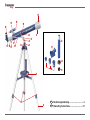
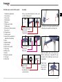
Aus diesen Teilen besteht dein Teleskop
1 Höhenfeineinstellung
2 Fokussiertrieb
3 Fokussierrohr
4 Zenitspiegel
5 Okulare
6 Sucherfernrohr-Halterung
7 Sucherfernrohr
8 Fernrohr (Teleskop-Tubus)
9 Sonnenblende
10 Objektivlinse
11 Feststellschraube
12 Schraube zur Höheneinstellung
13 Joch
14 Azimut-Sicherung
15 Stativkopf
16 Zubehörablage
17 Stativbein
18 Flügelschraube
19 Schraube
20 Okularverlängerung
21 Kompass
22 Mondfilter
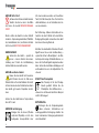
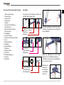
Befestige die Stativbeine mit Hilfe der Flügel-
schrauben, Unterlegscheiben und Flügelmut-
tern am Stativkopf.
Bringe die Mittelstrebe mit den kleinen
Schrauben an den Stativbein-Streben an.
– Wichtig! Der goldene Kreis der Mittelstrebe
muss nach oben zeigen.
Schraube zum
Schluss den
Zubehörteller
auf der Mittel-
strebe fest.
Der Aufbau
Du beginnst mit dem Aufbau des Stativs und
benötigst dazu folgende Teile:
Stativbeine u. Streben
Mittelstrebe
Stativkopf
Zubehörteller
Flügelschrauben
Flügelmuttern
Kleine Schrauben
Unterlegscheiben
Schraubwerkzeug
b
c
d

6
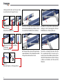
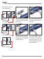
Jetzt wendest Du Dich dem Teleskop-Tubus
zu und findest noch folgende Teile vor:
Teleskop-Tubus
Sucherfernrohr
Sucherfernrohr-Halterung
Höhenfeineinstellung u. Schrauben
Zenitspiegel
Okularverlängerung
Okulare
Wendelschrauben u. Unterlegscheiben
Zuerst musst Du das Sucherfernrohr mit der
Sucherfernrohr-Halterung verbinden (einset-
zen und mit drei Schräubchen festdrehen).
Am Teleskop-Tubus erkennst Du zwei heraus-
ragende Gewinde. Dort schraubst Du die Hal-
terung mit dem Sucherfernrohr fest.
Als Nächstes schraubst Du die Höhenfeinein-
stellung an dem herausragenden silbernen
Metallstutzen des Teleskop-Tubus an.
Nun wird es schwierig! Am besten lässt Du
Dir von jemandem helfen. Du musst den Te-
leskop-Tubus mit dem Stativ verbinden. Nimm
dazu die Wendelschrauben mit den Unterleg-
scheiben und schraube den Tubus am Sta-
tivkopf an.
b
c
d
E

7
DE
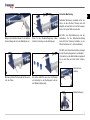
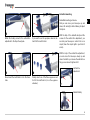
Azimutale Montierung
Azimutale Montierung bedeutet nichts an-
deres, als dass Du Dein Teleskop auf- und
abwärts und nach links und rechts bewegen
kannst, ohne das Stativ zu verstellen.
Mit Hilfe der Azimut-Sicherung und der
Schrauben für die Höhenfeineinstellung
kannst Du Dein Teleskop feststellen, um ein
Objekt zu fixieren (d. h. fest anzublicken).
Mit Hilfe der Höhenfeineinstellung bewegst
Du das Teleskop langsam auf- und abwärts.
Und nach Lösen der Azimut-Sicherung kannst
Du es nach links und nach rechts schwen-
ken.
Höhenfeinein-
stellung
Azimut-Sicherung
Bringe die Feststellschraube für die Höhen-
feineinstellung am Joch des Stativkopfes an.
Montiere jetzt den Zenitspiegel am Fokussier-
rohr des Tubus.
Wenn Du die Okularverlängerung nutzen
möchtest, befestige sie am Zenitspiegel.
Als Letztes wählst Du eines der drei Okulare
und befestigst es am Zenitspiegel (oder an
der Okularverlängerung).
F
G
H
I
1)
j

8
Vor der ersten Beobachtung
Bevor du zum ersten Mal etwas beobach-
test, musst du das Sucherfernrohr und das
Fernrohr aufeinander abstimmen. Du musst
das Sucherfernrohr so einstellen, dass du
dadurch das gleiche siehst wie durch das
Okular des Fernrohrs. Nur so kannst du bei
deinen Beobachtungen das Sucherfernrohr
zum groben Anpeilen von Objekten benutzen,
bevor du sie vergrößert durch das Fernrohr-
Okular betrachtest.
Sucherfernrohr und das Fernrohr aufein-
ander abstimmen
Schaue durch das Okular des Fernrohrs und
peile ein gut sichtbares Objekt (z.B. einen
Kirchturm) in einiger Entfernung an. Stelle es
mit dem Scharfeinstellungsrad scharf wie es
in Abb. 11 gezeigt wird.
Wichtig: Das Objekt muss mittig im Blickfeld
des Okulars zu sehen sein.
Tipp: Löse die Fixierschrauben für die Hö-
henfeineinstellung und die Vertikalachse, um
das Fernrohr nach rechts und links oder nach
oben und unten bewegen zu können. Wenn
du das Objekt richtig im Blickfeld hast, kannst
du die Fixierschrauben wieder anziehen, um
die Position des Fernrohrs zu fixieren.
Als nächstes schaust du durch das Sucher-
fernrohr. Du siehst das Bild deines angepeil-
ten Objekts in einem Fadenkreuz. Das Bild
steht auf dem Kopf.
Hinweis: Das Bild, das du durch das Sucher-
fernrohr siehst, steht auf dem Kopf, weil das
Bild durch die Optik umgekehrt wird. Das ist
völlig normal und kein Fehler.
Falls das Bild, das du durch das Sucherfern-
rohr siehst, nicht genau mittig im Fadenkreuz
steht (Abb. 12a), musst du an den Justier-
schrauben für das Sucherfernrohr drehen.
Drehe solange an den Schrauben, bis das
Bild mittig im Fadenkreuz steht (Abb. 12b).
Du solltest nun beim Blick durch das Okular
den gleichen Bildausschnitt wie beim Blick
durch das Sucherfernrohr (aber natürlich auf
dem Kopf stehend) sehen.
Wichtig: Erst wenn beide Bildausschnitte
gleich sind, sind Sucherfernrohr und Fern-
rohr richtig aufeinander abgestimmt.
1!
1@
b
a

9
DE
Verwendung des Mondfilters
Wenn dir das Bild des Mondes irgendwann zu
hell ist, dann kannst du den grünen Mondfilter
von unten in das Gewinde des Okulars ein-
schrauben. Das Okular kannst du dann ganz
normal in den Zenitspiegel einsetzen.
Das Bild das du nun beim Blick durch das
Okular siehst, ist grünlich. Die Helligkeit des
Mondes wird dadurch verringert, das Beob-
achten ist angenehmer.
Welches ist das richtige Okular?
Wichtig ist zunächst, dass du für den Beginn deiner Beobachtungen immer ein Okular mit der
höchsten Brennweite wählst. Du kannst dann nach und nach andere Okulare mit geringerer
Brennweite wählen. Die Brennweite wird in Millimeter angegeben und steht auf dem jeweiligen
Okular. Generell gilt: Je größer die Brennweite des Okulars, desto niedriger ist die Vergröße-
rung! Für die Berechnung der Vergrößerung gibt es eine einfache Rechenformel:
Brennweite des Fernrohrs : Brennweite des Okulars = Vergrößerung
Du siehst: Die Vergrößerung ist auch von der Brennweite des Fernrohrs abhängig. Dieses Tele-
skop beinhaltet ein Fernrohr mit 700 mm Brennweite. Daraus ergibt sich anhand der Rechen-
formel folgende Vergrößerung, wenn du ein Okular mit 20 mm Brennweite verwendest:
700 mm : 20 mm = 35fache Vergrößerung
Zur Vereinfachung habe ich dir hier eine Tabelle mit einigen Vergrößerungen
zusammengestellt:
Teleskop-Brennweite Okular-Brennweite Vergrößerung mit 1,5x Umkehrlinse
700 mm 24 mm 29x 43,5x
700 mm 20 mm 35x 52,5x
700 mm 12,5 mm 56x 84x
700 mm 6 mm 116 x 174x
700 mm 4 mm 175x 262,5x
F
2@
1%
E

10 10
Technische Daten:
• Bauart: achromatischer Refraktor
• Brennweite: 700 mm
• Objektivdurchmesser: 60 mm
• Sucher: 5x24
• Montierung: azimutal auf Stativ
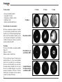
Mögliche Beobachtungsobjekte:
Nachfolgend haben wir für dich einige sehr
interessante Himmelskörper und Sternhaufen
ausgesucht und erklärt. Auf den zugehörigen
Abbildungen am Ende der Anleitung kannst du
sehen, wie du die Objekte durch dein Teles-
kop mit den mitgelieferten Okularen bei guten
Sichtverhältnissen sehen wirst:
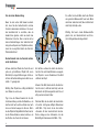
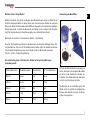
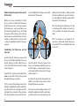
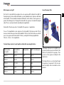
Der Mond
Der Mond ist der einzige natürliche Satellit der
Erde. (Abb. 13)
Durchmesser: 3.476 km
Entfernung: ca. 384.401 km
Der Mond ist seit prähistorischer Zeit bekannt.
Er ist nach der Sonne das zweithellste Objekt
am Himmel. Da der Mond einmal im Monat
um die Erde kreist, verändert sich ständig der
Winkel zwischen der Erde, dem Mond und
der Sonne; man sieht das an den Zyklen der
Mondphasen. Die Zeit zwischen zwei aufei-
nander folgenden Neumondphasen beträgt
etwa 29,5 Tage (709 Stunden).
1#
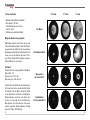
f=20 mm f=12 mm f=4 mm
Der Mond
Orion-Nebel (M 42)
Ringnebel in
der Leier (M 57)
Hantel-Nebel
im Füchslein (M 27)
1$
1%
1^

11
DE
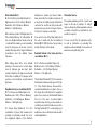
Orion-Nebel (M 42)
M 42 im Sternbild Orion (Abb. 14)
Rektaszension: 05:32,9 (Stunden : Minuten)
Deklination: –05:25 (Grad : Bogenminuten)
Entfernung: 1.500 Lichtjahre
Mit einer Entfernung von etwa 1500 Lichtjah-
ren ist der Orion-Nebel (Messier 42, kurz M
42) der hellste diffuse Nebel am Himmel – mit
dem bloßen Auge sichtbar, und ein lohnendes
Objekt für Teleskope in allen Größen, vom
kleinsten Feldstecher bis zu den größten erd-
gebundenen Observatorien und dem Hubble
Space Telescope.
Es handelt sich um den Hauptteil einer weit
größeren Wolke aus Wasserstoffgas und
Staub, die sich mit über 10 Grad gut über die
Hälfte des Sternbildes Orion erstreckt. Die
Ausdehnung dieser gewaltigen Wolke beträgt
mehrere hundert Lichtjahre.
Ringnebel in der Leier (M 57)
M 57 im Sternbild Leier (Abb. 15)
Rektaszension: 18:51,7 (Stunden : Minuten)
Deklination: +32:58 (Grad : Bogenminuten)
Entfernung: 2.000 Lichtjahre
Der berühmte Ringnebel M 57 im Sternbild
Leier wird oft als der Prototyp eines plane-
tarischen Nebels angesehen; er gehört zu
den Prachtstücken des Sommerhimmels der
Nordhalbkugel. Neuere Untersuchungen ha-
ben gezeigt, dass es sich aller Wahrschein-
lichkeit nach um einen Ring (Torus) aus hell
leuchtender Materie handelt, die den Zent-
ralstern umgibt (nur mit größeren Teleskopen
sichtbar), und nicht um eine kugel- oder ellip-
soidförmige Gasstruktur.
Würde man den Ringnebel von der Seitene-
bene betrachten, würde er dem Hantel-Nebel
(M 27) ähneln. Wir blicken bei diesem Objekt
genau auf den Pol des Nebels.
Hantel-Nebel im Füchslein (M 27)
M 27 im Sternbild Füchslein (Abb. 16)
Rektaszension: 19:59,6 (Stunden : Minuten)
Deklination: +22:43 (Grad : Bogenminuten)
Entfernung: 1.250 Lichtjahre
Der Hantel-Nebel (M 27) im Füchslein war der
erste planetarische Nebel, der überhaupt ent-
deckt worden ist. Am 12. Juli 1764 entdeckte
Charles Messier diese neue und faszinieren-
de Klasse von Objekten. Wir sehen dieses
Objekt fast genau von seiner Äquatorialebe-
ne. Würde man den Hantel-Nebel von einem
der Pole sehen, würde er wahrscheinlich die
Form eines Ringes aufweisen und dem An-
blick ähneln, den wir von dem Ringnebel M 57
kennen. Dieses Objekt kann man bereits bei
halbwegs guten Wetterbedingungen bei klei-
nen Vergrößerungen gut sehen.
Garantie & Service
Die reguläre Garantiezeit beträgt 2 Jahre und
beginnt am Tag des Kaufs. Um von einer ver-
längerten, freiwilligen Garantiezeit wie auf
dem Geschenkkarton angegeben zu profitie-
ren, ist eine Registrierung auf unserer Websi-
te erforderlich.
Die vollständigen Garantiebedingungen so-
wie Informationen zu Garantiezeitverlänge-
rung und Serviceleistungen können Sie unter
www.bresser.de/garantiebedingungen einse-
hen.

12
RISK to your child!
Never look through this device directly
at or near the sun. There is a risk of
BLINDING YOURSELF!
Children should only use this device under su-
pervision. Keep packaging materials (plastic
bags, rubber bands, etc.) away from children.
There is a risk of SUFFOCATION!
Fire/Burning RISK!
Never subject the device - especially
the lenses - to direct sunlight. Light ray
concentration can cause fires and/or burns.
RISK of material damage!
Never take the device apart. Please
consult your dealer if there are any de-
fects. The dealer will contact our service cen-
tre and send the device in for repair if needed.
Do not subject the device to temperatures ex-
ceeding 60 C.
TIPS on cleaning
Clean the lens (objective and eyepi-
ece) only with the cloth supplied or
some other soft lint-free cloth (e.g.
micro-fibre). Do not use excessive pressure -
this may scratch the lens.
Dampen the cleaning cloth with a spectacle
cleaning fluid and use it on very dirty lenses.
Protect the device against dirt and dust. Lea-
ve it to dry properly after use at room tempe-
rature. Then put the dust caps on and store
the device in the case provided.
RESPECT privacy!
This device is meant for private use.
Respect others‘ privacy – do not
use the device to look into other
people‘s homes, for example.
DISPOSAL
Dispose of the packaging material/s as
legally required. Consult the local au-
thority on the matter if necessary.

Your telescope consists of these parts:
1 Vertical fine adjustment
2 Focus wheel
3 Focus tube
4 Zenith mirror
5 Eyepiece
6 Finderscope holder
7 Finderscope
8 Telescope (Telescope tube)
9 Lens hood
10 Objective lens
11 Locking screw
12 Screw for the vertical fine
adjustment mechanism
13 Yoke
14 Azimuth Safety
15 Tripod head
16 Accessories caddy
17 Tripod leg
18 Wing screw
19 Screw
20 Eyepiece extender
21 Compass
22 Moon filter
Fix the tripod to the tripod head with the help
of the wing screw, washers and wing nuts.
Attach the middle span to the tripod spans
with the small screws. - Important! The gol-
den circle on the middle span must be poin-
ting upwards.
Finally, screw
the accessory
plate onto the
middle span.
Assembly
First, you assemble the tripod. For this, you‘ll
need the following parts:
Tripod leg and spans
Division bar
Tripod head
Accessories plate
Wing screw
Wing nuts
Small screws
Washers
Assembly tools for
screws and nuts
GB
13
b
c
d

14
Now, you turn to the telescope tube
and find the following pieces:
Telescope tube
Finderscope
Finderscope holder
Vertical adjustment
zenith mirror
eyepiece extenders and screws
Eyepieces
Spiral screws and Washers
First, you need to fix connect the finderscope
to the finderscope holder (insert and tighten
with three screws).
You will notice three threads protruding from
the telescope tube. Here, you can attach the
holder with the finderscope.
Next, screw the vertical fine adjustment to
the protruding silver metal supports on the
telescope tube.
Now it’s going to get difficult! It is best if you
let someone help you. You need to attach the
telescope tube to the tripod. To do so, take
the spiral screw with the washers and screw
the tube to the tripod head.
b
c
d
E

Azimuthal mounting
Azimuthal mounting just means
that you can move your telescope up and
down, left and right, without having to adjust
the tripod.
With the help of the azimuth safety and the
screws for the vertical fine adjustment, you
can lock your telescope in order to fix on an
object (have this object right in your field of
vision).
With the help of the vertical fine adjustment,
you can move the telescope slowly up and
down. And after you release the azimuth sa-
fety, you can move it right and left.
Vertical fine
adjustment
Azimuth Safety
Attach the locking screw for the vertical fine
adjustment to the tripod head yoke.
Now, mount the zenith mirror on to the focus
tube.
If you want to use the eyepiece extender, at-
tach it to the zenith mirror.
Finally, select one of the three eyepieces and
fix it to the zenith mirror (or on the eyepiece
extender).
F
G
H
I
1)
j
GB
15

16
Before looking through your telescope for
the first time
Before you look at something for the first
time, you must coordinate the finderscope
and the telescope lens. You have to position
the finderscope in such a way that you see
the same thing through it as you do through
the eyepiece of the telescope. This is the only
way you can use your finderscope to hone in
roughly on objects before you observe the-
se objects magnified through the telescope
eyepiece.
Coordinating the finderscope and the
telescope
Look through the telescope eyepiece and
hone in on a far away object that you can see
well (for instance, a church tower). Focus in
on the object with the focus knob in the way
shown in figure 11.
Important: The object must be located in the
middle of your field of vision when you look
through the telescope eyepiece.
Tip: If you loosen the locating screws for the
vertical fine adjustment and the vertical axis,
you will be able to move the telescope to the
right and left, up and down. When you have
the object well placed in your field of vision,
you can retighten the locating screws and fix
the position of the telescope.
Next, look through the finderscope. You will
see the image of the object you honed in on
in the crosshairs. The image will be upside
down.
Note: The image you see through the fin-
derscope is upside down because the lenses
are inverting it. This is completely normal, and
not an error.
1)
1!
b
a

GB
17
Use of the moon filter
If the image of the moon is too bright for you,
you can screw the green moon filter into the
bottom of the thread of the eyepiece. Then
you can set the eyepiece normally into the
zenith mirror.
The image that you see by looking through
the eyepiece is now greenish. The moon ap-
pears less bright, and so observation is more
pleasant.
Which eyepiece is right?
First of all, it is important that you always choose an eyepiece with the highest focal width for
the beginning of your observation. Afterwards, you can gradually move to eyepieces with smal-
ler focal widths. The focal width is indicated in millimeters, and is written on each eyepiece. In
general, the following is true: The larger the focal width of an eyepiece, the smaller the magnifi-
cation! There is a simple formula for calculating the magnification:
Focal width of the telescope tube : Focal width of the eyepiece = magnification
You see: The magnification is also depends on the focal width of the telescope tube. This te-
lescope contains a telescope tube with focal width of 700 mm. From this formula, we see that if
you use an eyepiece with a focal width of 20 mm, you will get the following magnification:
700 mm / 20 mm = 35 x magnification
To make things simpler, I’ve put together a table with some magnifications:
Telescope tube
focal width
Focal width of
eyepiece
Magnification with 1.5x inverting lens
700 mm 24 mm 29x 43,5x
700 mm 20 mm 35x 52,5x
700 mm 12,5 mm 56x 84x
700 mm 6 mm 116 x 174x
700 mm 4 mm 175x 262,5x
F
2@
1%
E

18
Technical data:
• Design: achromatic refractor
• Focal width: 700 mm
• Objective lens diameter: 60 mm
• Viewfinder: 5x24
• Mounting: azimuthal with tripod
Possible objects for observation:
We have compiled and explained a number
of very interesting celestial bodies and star
clusters for you. On the accompanying images
at the end of the instruction manual, you can
see how objects will appear in good viewing
conditions through your telescope using the
eyepieces that came with it.
The Moon
The moon is the Earth’s only natural satellite.
Figure 13)
Diameter: 3.476 km
Distance: approx. 384 401 km
The moon has been known to humans since
prehistoric times. It is the second brightest
object in the sky (after the sun). Because
the moon circles the Earth once per month,
the angle between the Earth, the moon and
the sun is constantly changing; one sees this
change in the phases of the moon. The time
between two consecutive new moon phases
is about 29.5 days (709 hours).
1%
1^
1$
1#
f=20 mm f=12 mm f=4 mm
The Moon
Orion Nebula (M 42)
Ring Nebula in Lyra
constellation (M 57)
Dumbbell Nebula in
the Vulpecula (Fox)
constellation (M 27)

GB
19
Orion Nebula (M 42)
M 42 in the Orion constellation (Figure 14)
Right ascension: 05:32.9 (Hours: Minutes)
Declination: -05:25 (Degrees: Minutes)
Distance: 1.500 light years
With a distance of about 1500 light years, the
Orion Nebula (Messier 42, abbreviation: M
42) is the brightest diffuse nebula in the sky
– visible with the naked eye, and a rewarding
object for telescopes in all sizes, from the
smallest field glass to the largest earthbound
observatories and the Hubble Space
Telescope.
When talking about Orion, we‘re actually
referring to the main part of a much larger
cloud of hydrogen gas and dust, which
spreads out with over 10 degrees over the half
of the Orion constellation. The expanse of this
enormous cloud stretches several hundred
light years.
Ring Nebula in Lyra constellation (M 57)
M 57 in the Lyra constellation (Figure 15)
Right ascension: 18:51.7 (Hours: Minutes)
Declination: -+32:58 (Degrees: Minutes)
Distance: 2.000 light years
The famous Ring Nebula M 57 in the
constellation of Lyra is often viewed as the
prototype of a planetary nebula; it is one of
the magnificent features of the Northern
Hemisphere’s summer sky. Recent studies
have shown that it is probably comprised of
a ring (torus) of brightly shining material that
surrounds the central star (only visible with
larger telescopes), and not of a gas structure
in the form of a sphere or an ellipsis.
If you were to look at the Ring Nebula from
the side, it would look like the Dumbbell
Nebula (M27). With this object, we’re looking
directly at the pole of the nebula.
Dumbbell Nebula in the Vulpecula (Fox)
constellation (M 27)
M 27 in the Fox constellation (Figure 16)
Right ascension: 19:59.6 (Hours: Minutes)
Declination: -+22:43 (Angle: Minutes)
Distance: 1.250 light years
The Dumbbell Nebula (M 27) in Fox was the
first planetary nebula ever discovered. On July
12, 1764, Charles Messier discovered this
new and fascinating class of objects. We see
this object almost directly from its equatorial
plane. If you could see the Dumbbell Nebula
from one of the poles, it would probably
reveal the shape of a ring, and we would see
something very similar to what we know from
the Ring Nebula (M 57). In reasonably good
weather, we can see this object well even with
small magnifications.
Warranty & Service
The regular guarantee period is 2 years and
begins on the day of purchase. To benefit
from an extended voluntary guarantee period
as stated on the gift box, registration on our
website is required.
You can consult the full guarantee terms
as well as information on extending the
guarantee period and details of our services at
www.bresser.de/warranty_terms.

Bresser GmbH
Gutenbergstr. 2
DE-46414 Rhede
Germany
www.bresser-junior.de
Irrtümer und technische Änderungen vorbehalten. · Errors and technical changes reserved. · Sous réserve d’erreurs et de modifications techniques.
Vergissingen en technische veranderingen voorbehouden. · Con riserva di errori e modifiche tecniche.
Queda reservada la posibilidad de incluir modificaciones o de que el texto contenga errores. · Erros e alterações técnicas reservados.
Manual_8843100_Teleskop-60-700-Koffer_de-en_BRESSER_v082017a
-
 1
1
-
 2
2
-
 3
3
-
 4
4
-
 5
5
-
 6
6
-
 7
7
-
 8
8
-
 9
9
-
 10
10
-
 11
11
-
 12
12
-
 13
13
-
 14
14
-
 15
15
-
 16
16
-
 17
17
-
 18
18
-
 19
19
-
 20
20


Bresser Junior 60/700 AZ1 Refractor Telescope Bedienungsanleitung
- Kategorie
- Teleskope
- Typ
- Bedienungsanleitung
- Dieses Handbuch ist auch geeignet für
in anderen Sprachen
Verwandte Papiere
Sonstige Unterlagen
-
National Geographic Telescope Microscope Set for Advanced Users Bedienungsanleitung
-
-
Bresser National Geographic AZ MOUNT Bedienungsanleitung
-
-
National Geographic Compact Telescope and Microscope Set Bedienungsanleitung
-
National Geographic 50/360 Telescope Bedienungsanleitung
-
-
-
Vixen X002521 Bedienungsanleitung
-
Explore Scientific 0114220 Bedienungsanleitung