Yamaha 1 Bedienungsanleitung
- Kategorie
- Empfänger
- Typ
- Bedienungsanleitung
Dieses Handbuch eignet sich auch für

R
C
LS
RS
LFE
L
R
C
LS
RS
LFE
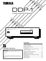
NATURAL SOUND DIGITAL PROCESSOR DDP–1
PARAMETERMENU
MODE
TEST
DDP-1
NATURAL SOUND DIGITAL PROCESSOR
CONTENTS
Safety Instructions ......................................... 2
Profile of This Unit ......................................... 4
Speaker System Setup .................................. 5
Connections ................................................... 6
Turning On/Off the Power of This Unit ........... 8
Table of Functions ......................................... 9
Adjustments Before Operation .................... 10
Playing an AC-3 Source .............................. 14
Adjusting Output Levels ............................... 14
Adjusting Delays and Dynamic Range ........ 16
Specifications .............................................. 18
Troubleshooting ........................................... 18
Block Diagram ............................................. 19
OWNER’S MANUAL
IMPORTANT!
Please record the serial number of this unit in the
space below.
Serial No.:
The serial number is located on the rear of the unit.
Retain this Owner’s Manual in a safe place for future
reference.

2
1 Read Instructions – All the safety and operating
instructions should be read before the unit is operated.
2 Retain Instructions – The safety and operating instructions
should be retained for future reference.
3 Heed Warnings – All warnings on the unit and in the
operating instructions should be adhered to.
4 Follow Instructions – All operating and other instructions
should be followed.
5 Water and Moisture – The unit should not be used near
water – for example, near a bathtub, washbowl, kitchen
sink, laundry tub, in a wet basement, or near a swimming
pool, etc.
6 Carts and Stands – The unit should be used only with a
cart or stand that is recommended by the manufacturer.
6A A unit and cart combination should be
moved with care. Quick stops,
excessive force, and uneven surfaces
may cause the unit and
cart combination to overturn.
7 Wall or Ceiling Mounting – The unit should be mounted to
a wall or ceiling only as recommended by the
manufacturer.
8 Ventilation – The unit should be situated so that its
location or position does not interfere with its proper
ventilation. For example, the unit should not be situated
on a bed, sofa, rug, or similar surface, that may block the
ventilation openings; or placed in a built-in installation,
such as a bookcase or cabinet that may impede the flow
of air through the ventilation openings.
9 Heat – The unit should be situated away from heat
sources such as radiators, stoves, or other appliances
that produce heat.
10 Power Sources – The unit should be connected to a
power supply only of the type described in the operating
instructions or as marked on the unit.
11 Power-Cord Protection – Power-supply cords should be
routed so that they are not likely to be walked on or
pinched by items placed upon or against them, paying
particular attention to cords at plugs, convenience
receptacles, and the point where they exit from the unit.
12 Cleaning – The unit should be cleaned only as
recommended by the manufacturer.
13 Nonuse Periods – The power cord of the unit should be
unplugged from the outlet when left unused for a long
period of time.
14 Object and Liquid Entry – Care should be taken so that
objects do not fall into and liquids are not spilled into the
inside of the unit.
15 Damage Requiring Service – The unit should be serviced
by qualified service personnel when:
A. The power-supply cord or the plug has been
damaged; or
B. Objects have fallen, or liquid has been spilled into the
unit; or
C. The unit has been exposed to rain; or
D. The unit does not appear to operate normally or
exhibits a marked change in performance; or
E. The unit has been dropped, or the cabinet damaged.
16 Servicing – The user should not attempt to service the unit
beyond those means described in the operating
instructions. All other servicing should be referred to
qualified service personnel.
17 Power Lines – An outdoor antenna should be located
away from power lines.
18 Grounding or Polarization – Precautions should be taken
so that the grounding or polarization is not defeated.
SAFETY INSTRUCTIONS
RISK OF ELECTRIC SHOCK
DO NOT OPEN
CAUTION: TO REDUCE THE RISK OF
ELECTRIC SHOCK, DO NOT REMOVE
COVER (OR BACK). NO USER-SERVICEABLE
PARTS INSIDE. REFER SERVICING TO
QUALIFIED SERVICE PERSONNEL.
The lightning flash with arrowhead
symbol, within an equilateral triangle,
is intended to alert you to the
presence of uninsulated “dangerous
voltage” within the product’s
enclosure that may be of sufficient
magnitude to constitute a risk of
electric shock to persons.
The exclamation point within an
equilateral triangle is intended to alert
you to the presence of important
operating and maintenance
(servicing) instructions in the
literature accompanying the
appliance.
•
Explanation of Graphical Symbols
CAUTION
WARNING
TO REDUCE THE RISK OF FIRE OR
ELECTRIC SHOCK, DO NOT EXPOSE THIS
UNIT TO RAIN OR MOISTURE.

3
1. IMPORTANT NOTICE : DO NOT MODIFY THIS UNIT!
This product, when installed as indicated in the
instructions contained in this manual, meets FCC
requirements. Modifications not expressly approved by
Yamaha may void your authority, granted by the FCC, to
use the product.
2. IMPORTANT : When connecting this product to
accessories and/or another product use only high quality
shielded cables. Cable/s supplied with this product
MUST be used. Follow all installation instructions.
Failure to follow instructions could void your FCC
authorization to use this product in the USA.
3. NOTE : This product has been tested and found to
comply with the requirements listed in FCC Regulations,
Part 15 for Class “B” digital devices. Compliance with
these requirements provides a reasonable level of
assurance that your use of this product in a residential
environment will not result in harmful interference with
other electronic devices.
This equipment generates/uses radio frequencies and, if
not installed and used according to the instructions
found in the users manual, may cause interference
harmful to the operation of other electronic devices.
Compliance with FCC regulations does not guarantee that
interference will not occur in all installations. If this product
is found to be the source of interference, which can be
determined by turning the unit “OFF” and “ON”, please try
to eliminate the problem by using one of the following
measures:
Relocate either this product or the device that is being
affected by the interference.
Utilize power outlets that are on different branch (circuit
breaker or fuse) circuits or install AC line filter/s.
In the case of radio or TV interference, relocate/reorient the
antenna. If the antenna lead-in is 300 ohm ribbon lead,
change the lead-in to coaxial type cable.
If these corrective measures do not produce satisfactory
results, please contact the local retailer authorized to
distribute this type of product. If you can not locate the
appropriate retailer, please contact Yamaha Electronics
Corp., U.S.A. 6660 Orangethorpe Ave, Buena Park, CA
90620.
The above statements apply ONLY to those products
distributed by Yamaha Corporation of America or its
subsidiaries.
FCC INFORMATION (for US customers only)
YAMAHA and the Electronic Industries Association’s
Consumer Electronics Group want you to get the most out of
your equipment by playing it at a safe level. One that lets the
sound come through loud and clear without annoying blaring
or distortion – and, most importantly, without affecting your
sensitive hearing.
Since hearing damage from loud sounds is often
undetectable until it is too late, YAMAHA and the
Electronic Industries Association’s Consumer
Electronics Group recommend you to avoid
prolonged exposure from excessive volume levels.
We Want You Listening For A Lifetime (for US customers only)
Caution: Read this before operating your unit
1 To assure the finest performance, please read this
manual carefully. Keep it in a safe place for future
reference.
2 Install this unit in a cool, dry, clean place – away from
windows, heat sources, sources of excessive vibration,
dust, moisture and cold. Avoid sources of humming
(transformers, motors). To prevent fire or electrical
shock, do not expose the unit to rain and water.
3 Do not operate the unit upside-down. It may overheat,
possibly causing damage.
4 Never open the cabinet. If something drops into the set,
contact your dealer.
5 Do not use force on switches, controls or connection
wires. When moving the unit, first disconnect the power
plug and the wires connected to other equipment.
Never pull the wires themselves.
6 Do not attempt to clean the unit with chemical solvents;
this might damage the finish. Use a clean, dry cloth.
7 To prevent lightning damage, pull out the power cord
and remove the antenna cable during an electrical
storm.
8 When not planning to use this unit for long periods
of time (ie., vacation, etc.), disconnect the AC power
plug from the wall outlet.
9 Be sure to read the “TROUBLESHOOTING” section
regarding common operating errors before concluding
that the unit is faulty.
10 AC outlet
Do not connect audio equipment to the AC outlet on the
rear panel if that equipment requires more power than
the outlet is rated to provide.
The apparatus is not disconnected from the AC power
source as long as it is connected to the wall outlet, even if
the apparatus itself is turned off.

4
Thank you for purchasing the Yamaha DDP-1, a sophisticated
digital sound processor designed specifically for decoding
Dolby AC-3.
This unit consists of an AC-3 RF demodulator, an AC-3
decoder and other original Yamaha functions developed using
the newest technology to reproduce AC-3 encoded sources
precisely as movie sound creators intended. AC-3 will lead
listeners into a totally new sound experience.
This unit is equipped with “discrete” terminals for sending AC-3
multi-channel audio signals individually. The audio amplifier or
receiver must have “discrete” input terminals to receive the
signals from the DDP-1. The use of Yamaha RX-V2090, a
multi-channel audio/video receiver equipped with discrete input
terminals combined with this unit is an ideal choice for the
purpose of experiencing AC-3 sound, and this is the best
system we recommend.
• Dynamic range (sound scale) of source can be
changed so that it will be suitable for the listening
conditions.
• Output of low bass from any channel can be
assigned to either the MAIN OUTPUT terminals or
SUBWOOFER OUTPUT terminal to maximize
system performance.
• Output of LFE can be assigned to either the MAIN
OUTPUT terminals or SUBWOOFER OUTPUT
terminal to maximize system performance.
• Test tone generator helps you adjust speaker level
balance.
• Center channel output can be sent to the main
speakers if you do not use a center channel
speaker.
• Three types of inputs (AC-3 RF, AC-3 Digital
Optical and Coaxial) are available for future use.
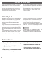
Dolby AC-3 is a new generation of multi-channel digital audio
technology, or the newest spatial sound processing format
developed for 35 mm film-movies by employing a new kind of
low bit-rate audio coding.
Dolby Surround AC-3 is a digital surround sound system that
provides completely independent multi-channel audio to
consumers.
In multi-channel form, Dolby Surround AC-3 provides five full
range channels in what is sometimes referred to as a “3/2”
configuration: three front channels (left, center and right), plus
two surround channels. A sixth bass-only effect channel is also
provided for output of LFE (low frequency effect), or low bass
effects that are independent of other channels. This channel is
counted as 0.1, thus giving rise to the term 5.1 channels in
total.
Compared to Dolby Pro Logic that is referred to a “3/1” system
(left front, center, right front and just one surround channel),
Dolby Surround AC-3 features two surround channels, called
stereo or split surrounds, each offering the same full range
fidelity as the three front channels.
Sound of wide dynamic range reproduced by the five full range
channels presents listeners much excitement that has never
been experienced before. Precise sound orientation by the
discrete digital sound processing expands realism that the
original movie possesses.
Laser Disc is a home audio format that could benefit from
Dolby AC-3. In the near future, Dolby AC-3 will also be applied
to DBS, CATV, DVD and HDTV. The ongoing release of Dolby
Stereo Digital theatrical films now underway will provide an
immediate source of AC-3 encoded video software.
Manufactured under license from Dolby Laboratories Licensing
Corporation. “Dolby”, “AC-3”, and the double-D symbol are
trademarks of Dolby Laboratories Licensing Corporation.
Copyright 1992 Dolby Laboratories, Inc. All rights reserved.
PROFILE OF THIS UNIT
What
’s Dolby AC-3?
Features of this unit

5
SPEAKER SYSTEM SETUP
As described on page 4, we recommend you to use this unit
connecting with the Yamaha RX-V2090. If you have already
set up a speaker system for the RX-V2090, you do not need to
prepare a new speaker system for this unit. Some functions on
this unit have been already preset to be suitable when this unit
is used with a speaker system for the RX-V2090. (Refer to
page 10 for details about those functions.)
This unit will provide the best performance with a five-speaker
system setup: one pair of main speakers for main sound
reproduction, one pair of surround speakers for effect and
surround sounds and one center speaker for dialog. A simple
speaker system excluding a center speaker will still provide
impressive ambience and effects, however, and may be a
good way to begin with this unit. You can always upgrade to
the five speaker system later.
* For the best performance of the RX-V2090, the system
needs one more pair of surround speakers at the front
position. (Refer to the owner’s manual of the RX-V2090 for
details.)
Main speakers should be high performance models and have
enough power handling capacity to accept the maximum
output of your system.
Surround speakers and a center speaker do not have to be
equal to the main speakers. For precise sound localization,
however, it is ideal to use high performance models that can
reproduce sounds in full range.
If for some reason it is not practical to use a center speaker,
you can enjoy AC-3 effect without it. Best results, however, are
obtained with the full system.
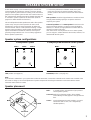
Main: In normal position. (The position of your present
stereo speaker system.)
Surround: Behind your listening position, facing slightly
inward. Nearly six feet (approx. 1.8 m) up from the
floor.
Center: Precisely between the main speakers. (To avoid
interference with TV sets, use a magnetically
shielded speaker.)
Set the center channel mode (C2. CENTER SP.) to the SML or
LRG position. (See page 10.)
Set the center channel mode (C2. CENTER SP.) to the
PHANTOM position. (See page 10.)
Speaker placement
Five-speaker system A simple system without a center speaker
Main L
Main R
Center
Surround L
Surround R
Main L Main RCenter
Surround L Surround R
Main L Main R
Surround L Surround R
Speaker system configurations
Note
If you will add a subwoofer in your system that includes the RX-V2090, connect the subwoofer to the “LOW PASS” terminal of the
RX-V2090. In doing so, the overall adjustment of speaker output levels including the subwoofer can be done with the master
VOLUME control of the RX-V2090.

6
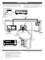
Note 1) If this unit is connected to the RX-V2090, no
connection is needed to this terminal. By the output
mode selections on function C2 to C5, low frequency
signals including signals from the LFE channel can
be output from the main L and R speakers. (See
page 10 for details.)
If the amplifier has a discrete subwoofer input
terminal, connect it with this unit’s SUBWOOFER
OUTPUT terminal.
Note 2) Do not connect a normal audio output terminal of a
laserdisc player etc. to this unit’s AC-3 RF terminal.
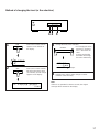
CONNECTIONS
•
Before attempting to make any connections to or from this
unit, be sure to first switch OFF the power to this unit and to
any other components to which connections are being made.
•
When making connections between this unit and other
components, be sure all connections are made correctly, L
(left) to L, R (right) to R. Also, refer to the owner’s manual for
each component to be connected to this unit.
AC-3 RF OUT
INPUT
OUTPUT
OPTICAL COAXIAL
AC–3 DIGITAL
AC–3 RF
MAIN CENTER SURROUND
SUBWOOFER
I20V 60Hz
I.6A MAX.
200W MAX.
UNSWITCHED
AC OUTLET
5CH
DISCRT
INPUT
LD/TV
MAIN
LD/TV
CENTER
LD/TV
SURROUND
AC-3 laserdisc player or another AC-3 unit
Refer to the next page.
Refer to “Note 1”
below.
Refer to “Note 2”
below.
To AC outlet
Audio cord
(not included)
Audio cords
(included)
Audio cords
(included)
(U.S.A. model)
Amplifier or receiver (RX-V2090 etc.)
equipped with 5-ch discrete AC-3 terminals

7
AC-3 DIGITAL OPTICAL/COAXIAL terminals
These terminals input AC-3 signals in digital signal format.
They are provided for future use.
* Do not remove the cover of the OPTICAL terminal unless
you will use this terminal in order to protect the terminal from
dust.
AC OUTLET (UNSWITCHED)
The power cord of any audio/video unit can be connected to
this outlet.
The power to this outlet is not controlled by this unit’s POWER
switch. This outlet will supply power to the connected unit even
if this unit is turned off.
The maximum power that can be connected to this outlet is
200 watts.
OPTICAL COAXIAL
AC–3 DIGITAL
I20V 60Hz
I.6A MAX.
200W MAX.
UNSWITCHED
AC OUTLET

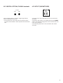
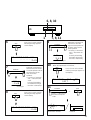
TURNING ON/OFF THE POWER OF THIS UNIT
To turn on the power
Press the POWER switch.
When an AC-3 data is input to this unit, the characteristics of
the data (from the source) are shown.
ex.)
When there is no data input, or data other than AC-3 is input to
this unit, the input terminal on the rear of this unit used for
connection is shown.
ex.)
About the Audio Code
Audio code shows the formation and the number of channels.
ch : 3/2
To turn off the power
Press the POWER switch so that the display turns off.
Turn on the power of this unit when you will play an AC-3 source (an AC-3 laserdisc etc.), or if you desire to make some
adjustments or mode setting changes to this unit.
YAMAHA
AC– 3 DECODER
AC– 3 DECODING
fs=48k ch : 3/2
NO AC–3 DATA
INPUT RF
Sampling frequencies Audio code
3:Three channel outputs at the front:
left main, center and right main
2:Two channel outputs at the front:
left main and right main
1:Center channel output only at the
front
2:Two channel outputs at the rear:
left surround and right surround
1:Monaural surround channel output
at the rear
0:No output at the rear
The display turns on and shows this message for about 2
seconds, and then turns into the following messages.
PARAMETERMENU
MODE
TEST
8

9
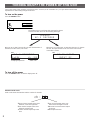
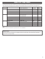
TABLE OF FUNCTIONS
MODE MENU (Function) PARAMETER Preset value Step of
(Category) (Control range/Choices) (Position) change
A 1. CENTER DELAY 0 ms to 5 ms 0 ms 1 ms
2. SURROUND DELAY 0 ms to 15 ms 5 ms 1 ms
3. DYNAMIC RANGE MAX/STANDARD MAX –
4. HIGH LEVEL CUT SCALE
* 0.0 to 1.0 1.0 0.2
5. LOW LEVEL BOOST SCALE
* 0.0 to 1.0 1.0 0.2
B 1. TEST: OFF/ON LEFT/CENTER/RIGHT/ OFF –
RIGHT SURROUND/
LEFT SURROUND
2. LEFT SURROUND LEVEL –6 dB to +6 dB 0 dB 1 dB
3. RIGHT SURROUND LEVEL –6 dB to +6 dB 0 dB 1 dB
4. LFE MIX LEVEL MUTE, –20 dB to 0 dB 0 dB 1 dB
5. OUTPUT TRIM –9 dB to 0 dB 0 dB 0.5 dB
C 1. INPUT RF/OPTICAL/COAXIAL RF –
2. CENTER SPEAKER SMALL/LARGE/PHANTOM SMALL –
3. REAR SPEAKERS SMALL/LARGE SMALL –
4. MAIN SPEAKERS SMALL/LARGE LARGE –
5. LFE/BASS OUT MAIN/SUBWOOFER MAIN –
The following 15 functions on this unit allows you to change several adjustments and mode settings for enhancing the performance
of your audio system including this unit. For adjustment or mode setting change on each menu function, refer to page 10–17.
Note
*
: Items A4 and A5 are adjustable only when item A3 is set to “STANDARD”.
Memory back up
Parameter changes you made the last time will remain memorized even if the power of this unit is switched off or the power cord
is disconnected. However, if the power is not supplied for more than about two weeks, all parameters will be automatically
changed back to the original settings.

10
C1. INPUT
Choices: RF/OPT./COAX.
Preset position: RF
Selects the name of the input terminal on the rear of this unit
used for the connection with an AC-3 laserdisc player or
another AC-3 unit.
C2. CENTER SPEAKER
Choices: SML/LRG/PHANTOM
Preset position: SML
SML: Select this position when you use a center speaker
that is smaller than the main speakers. In this
position, low bass signals (below 90 Hz) at the
center channel are output from the MAIN OUTPUT
terminals.
LRG: Select this position when your center speaker is
approximately the same size as the main speakers.
PHANTOM:
Select this position when you do not have a center
speaker. The center channel sound will be output
from the left and right main speakers.
C3. REAR SPEAKERS
Choices: SMALL/LARGE
Preset position: SMALL
SMALL: Select this position if your rear surround speakers do
not have a high ability for bass reproduction.
In this position, low bass signals (below 90 Hz) at the
surround channels are output from the MAIN
OUTPUT terminals.
LARGE: Select this position if your rear surround speakers
have a high ability for bass reproduction, or a
subwoofer is connected to the surround speaker in
parallel.
In this position, full range signals are output from the
SURROUND OUTPUT terminals.
C4. MAIN SPEAKERS
Choices: SMALL/LARGE
Preset position: LARGE
SMALL: Select this position if your main speakers do not
have a high ability for bass reproduction. However, if
your system does not include a subwoofer, do not
select this position.
In this position, low bass signals (below 90 Hz) at the
main channels are output from the SUBWOOFER
OUTPUT terminals (if the SUBWOOFER position is
selected on “C5. LFE/BASS OUT”).
LARGE: Be sure to select this position, if this unit is
connected to an amplifier or receiver (RX-V2090
etc.) equipped with 5-ch discrete AC-3 input
terminals.
In this position, full range signals present at the main
channels are output from the MAIN OUTPUT
terminals.
Select this position if your main speakers have a
high ability for bass reproduction.
C5. LFE/BASS OUT
Choices: MAIN/SUBWOOFER
Preset position: MAIN
MAIN: Be sure to select this position, if this unit is
connected to an amplifier or receiver (RX-V2090
etc.) equipped with 5-ch discrete AC-3 input
terminals.
In this position, full range signals present at the main
channels, signals from the LFE channel and other
low bass signals that are selected on C2 to C4 to be
distributed from other channels are output from the
MAIN OUTPUT terminals.
SUBWOOFER:
Select this position if this unit is connected to an
amplifier or receiver equipped with a subwoofer (or
LFE) input terminal.
In this position, signals at LFE channel and other low
bass signals that are selected on C2 to C4 to be
distributed from other channels are output from the
SUBWOOFER OUTPUT terminals.
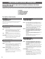
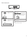
ADJUSTMENTS BEFORE OPERATION
SELECTING THE INPUT AND OUTPUT MODES SUITABLE FOR YOUR
SPEAKER SYSTEM
This unit provides you the following five functions to determine the modes of input and distribution of output signals to speakers
suitable for your audio system. C4 and C5 have been already preset in the position suitable for using this unit with the RX-V2090.
Description of each function
C1. INPUT
C2. CENTER SPEAKER
C3. REAR SPEAKERS
C4. MAIN SPEAKERS
C5. LFE/BASS OUT

PARAMETERMENU
MODE
TEST
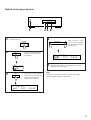
11
1
Turn the power on.
2
Press once or more until “C”
appears on the left side of
the display.
3
Press once or more until the
title of function on which you
will change the selection
appears on the display.
4
Press “+” side or “–” side
once or more so that the
arrow points the position
you will select.
5
Repeat step 3 and 4 to change selections on other
functions in the same way.
Note
If there is no operation for about 5 seconds, the original
message will be restored on the display.
MODE
MENU
PARAMETER
Method of changing selections
1 2 3 4
C1. INPU
RF O
C1. INPUT
RF OPT. COAX.
C1. INPUT
RF OPT. COAX.

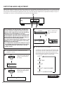
BEFORE MAKING THE ADJUSTMENT ON THIS UNIT
Be sure to adjust the output level balance among the
left main, center, right main and surround channels for
Dolby Pro Logic on the amplifier (or receiver)
connected to this unit using a test tone generator built
into the amplifier. Adjust the balance so that the levels
of those channels become almost the same when you
hear the test tone at the listening position.
If you have finished adjusting the output balance on the
amplifier, then go on to the adjustment on this unit by
following the procedure below.
* For output balance adjustment for Dolby Pro Logic on
the RX-V2090, refer to the instructions on the section
“ADJUSTMENT BEFORE OPERATION” of the RX-
V2090’s manual.
1
Turn down the volume to a minimum level on the
amplifier or receiver.
2
Press once or more until “B”
appears on the left side of
the display.
3
Press once or more until the
following message appears
on the display.
4
Press “+” side once so
that the arrow points
“ON”.
5
Turn up the volume on the amplifier.
You will hear a test tone (like pink noise) from the left
main speaker, then the center speaker, then the right
main speaker, then the right surround speaker and
then the left surround speaker, for about two seconds
each. The display changes as shown below.
12
MODE
MENU
PARAMETER
LEFT
CENTER
RIGHT
RIGHT SURROUND
LEFT SURROUND
OUTPUT BALANCE ADJUSTMENT
Adjusting the output level balance among all the channels are very important to maximize the performance of your system including
this unit. This unit lets you adjust the sound output level balance between the left and right surround channels using the built-in test
tone generator. Before making the adjustment on this unit, you should make the output balance adjustment for Dolby Pro Logic on
the amplifier (or receiver) connected with this unit. Follow the instructions below.
PARAMETERMENU
MODE
TEST
2 4
3
Continued
B1. TEST :
B1. TEST : OFF ON
OFF ON
FT
MODE
TEST
Lights up.

6
Press once or more until the
following message appears
on the display.
7
Adjust the sound level of
the test tone from the left
surround speaker to be at
the same level as the
main and center
speakers.
* Pressing “+” increases
and “–” decreases the
value.
Pressing and holding
the button will change
the value continuously.
8
Press once or more until the
following message appears
on the display.
9
Adjust the sound level of
the test tone from the
right surround speaker to
be at the same level as
other speakers.
* Pressing “+” increases
and “–” decreases the
value.
Pressing and holding
the button will change
the value continuously.
10
When the adjustments are finished;
Press once or more until the
following message appears on
the display.
11
The test tone will stop.
13
PARAMETER
MENU
PARAMETER
MENU
PARAMETERMENU
MODE
TEST
7, 9, 111
6, 8, 10
. LVL
..
0dB
Changes.
B3. RIGHT SUR. LVL
........
0dB
LVL
..
0dB
Changes.
B1. TEST : OFF ON
LEFT
PARAMETER
T : OFF ON
MODE
TEST
Goes off.
MENU
B2. LEFT SUR. LVL
........
0dB
MODE
or
Press “–” side once so
that the arrow points
“OFF”.

14
1
Turn down the volume to minimum on the amplifier.
2
Turn the power on to the AC-3 unit, this unit, the
amplifier, the monitor etc.
3
If necessary, change the input mode setting on the
amplifier to the “5-ch discrete AC-3 input”.
* For the RX-V2090, press the LD/TV button on the
front panel of the RX-V2090 so that “5 CH DISCRT”
appears on the display. (Refer to the section “Dolby
Surround AC-3” of the RX-V2090’s manual.)
4
Play an AC-3 source on the AC-3 unit.
5
Turn up the volume on the amplifier.
6
If desired, adjust output levels, delays, dynamic range,
etc. on this unit. (See page 14–17 for details.)
PARAMETERMENU
MODE
TEST
PLAYING AN AC-3 SOURCE
ADJUSTING OUTPUT LEVELS
The following output level adjustments are possible on this unit. Adjust them as you prefer, monitoring source sound.
B2. LEFT SURROUND LEVEL
B3. RIGHT SURROUND LEVEL
B4. LFE MIX LEVEL
B5. OUTPUT TRIM
Description of each function
B2. LEFT SURROUND LEVEL
Control range: –6 dB to +6 dB (in 1 dB step)
Preset value: 0 dB
Adjusts the output level at the left surround channel.
You had already adjusted the level in “OUTPUT BALANCE
ADJUSTMENT” on page 13, however you can change the
level if you wish.
B3. RIGHT SURROUND LEVEL
Control range: –6 dB to +6 dB (in 1 dB step)
Preset value: 0 dB
Adjusts the output level at the right surround channel.
You had already adjusted the level in “OUTPUT BALANCE
ADJUSTMENT” on page 13, however you can change the
level if you wish.
B4. LFE MIX LEVEL
Control range: MUTE, –20 dB to 0 dB (in 1 dB step)
Preset value: 0 dB
Adjusts the output level at the LFE (low frequency effect)
channel. If the LFE signals are mixed with signals at the main
channels, only the level of the LFE signals are adjusted.
When adjusted to MUTE, only the LFE sound will not be
output.
B5. OUTPUT TRIM
Control range: –9 dB to 0 dB (in 0.5 dB step)
Preset value: 0 dB
Adjusts the output level at all channels.

15
1
Press once or more until “B”
appears on the left side of
the display.
2
Press once or more until the
title of function whose level
you will change appears on
the display.
3
Adjust the level.
Pressing “+” increases
and “–” decreases the
value.
Pressing and holding the
button will change the
value continuously.
4
Repeat step 2 and 3 to adjust levels on other functions
in the same way.
Note
If there is no operation for about 5 seconds, the original
message will be restored on the display.
MODE
MENU
PARAMETER
Method of adjusting levels
PARAMETERMENU
MODE
TEST
1 2 3
B1. TEST :
B2. LEFT SUR. LVL
........
0dB
. LVL
..
0dB
Changes.

16
ADJUSTING DELAYS AND DYNAMIC RANGE
This unit provides you with the following functions to make the AC-3 sound field suitable for the conditions of your listening room.
A1. CENTER DELAY
A2. SURROUND DELAY
A3. DYNAMIC RANGE
A4. HIGH LEVEL CUT SCALE
A5. LOW LEVEL BOOST SCALE
Description of each function
A1. CENTER DELAY
Control range: 0 ms to 5 ms (in 1 ms step)
Preset value: 0 ms
Adjusts the delay between the main sounds (at the main
channels) and dialog etc. (at the center channel).
The larger the value, the later the dialog is generated.
A2. SURROUND DELAY
Control range: 0 ms to 15 ms (in 1 ms step)
Preset value: 5 ms
Adjusts the delay between the main sounds (at the main
channels) and the effect sounds (at the surround channels).
The larger the value, the later the effect sounds are generated.
A3. DYNAMIC RANGE
Choices: MAX/STANDARD
Preset position: MAX
MAX: “Dynamic range” is the difference between the
maximum level and the minimum level of sounds.
Sounds on a movie originally designed for movie
theaters feature very wide dynamic range.
AC-3 technology can bring the original sound track
into a home audio format with this wide dynamic
range unchanged.
In this position, an AC-3 source is reproduced in the
original sound track’s wide dynamic range providing
you with powerful sounds like a movie theater.
Selecting this position will be more ideal if you can
listen to a source in a high output level in a room
specially soundproofed for audio/video enjoyment.
STANDARD:
Powerful sounds of extremely wide dynamic range
are not always suitable for home use. Depending
upon the condition of your listening environment, it
may not possible to increase the sound output level
as high as a movie theater, however, in a level
proper for listening to in your room, the low level
parts of source sound cannot be heard as well
because they will be lost among noises in your
environment.
AC-3 technology also makes it possible to reduce an
original sound track’s dynamic range for a home
audio format by “compressing” the data.
In this position, an AC-3 source is reproduced in the
“compressed” dynamic range of the source suitable
for low level listening.
If you desire, you can also adjust the dynamic range
on function A4 and A5 only when this position is
selected. (See the right side for details.)
A4. HIGH LEVEL CUT SCALE
Control range: 0.0 to 1.0 (in 0.2 step)
Preset value: 1.0
Adjusts the dynamic range of high level signals of source. The
larger the value, the range is more reduced. The smaller the
value, the range is more widened.
Note: This function is available only when the “STANDARD”
position is selected on the function A3.
A5. LOW LEVEL BOOST SCALE
Control range: 0.0 to 1.0 (in 0.2 step)
Preset value: 1.0
Adjusts the dynamic range of low level signals of source. The
larger the value, the range is more widened. The smaller the
value, the range is more reduced.
Note: This function is available only when the “STANDARD”
position is selected on the function A3.

17
1
Press once or more until “A”
appears on the left side of
the display.
2
Press once or more until the
title of function whose level
(or selection) you will change
appears on the display.
3
Change the level (or the selection).
* For changing the value,
pressing “+” increases
and “–” decreases the
value.
Pressing and holding
the button will change
the value continuously.
4
Repeat step 2 and 3 to make changes on other
functions in the same way.
Note
If there is no operation for about 5 seconds, the original
message will be restored on the display.
MODE
MENU
PARAMETER
Method of changing the level (or the selection)
PARAMETERMENU
MODE
TEST
1 2 3
A1. CENT
..
A1. CENTER DELAY
........
0ms
DELAY
....
0ms
Changes.

18
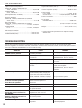
SYMPTOM
The unit fails to turn on when the
POWER switch is pressed.
No sound.
Sound “hums”.
Poor bass reproduction.
Sound output level to either or both
of the rear surround speakers is
lower than other speakers.
No sound from the center speaker.
No output of LFE sound.
Whole sound level is low, even
though the volume is increased on
the amplifier.
The difference of sound level
between a high level part and a low
level part is too great.
Noise from nearby TV or tuner.
CAUSE
Power cord is not plugged in or is not
completely inserted.
Incorrect input or output cord
connections.
Improper input mode selection.
Improper input mode selection on the
amplifier.
Incorrect cord connections.
The setting of LFE/BASS OUT is at the
SUBWOOFER position, though your
system does not include a subwoofer.
Output mode selection for each channel
(MAIN, CENTER or REAR) is improper.
Sound output level to either or both of
the rear surround speakers is
decreased.
The setting of CENTER SP. is at the
PHANTOM position.
The output level of LFE (LFE MIX LVL)
is adjusted to MUTE.
Output level (OUTPUT TRIM)
adjustment on this unit is low.
The setting of the DYNAMIC RANGE is
at the MAX position.
This unit is too close to the affected
equipment.
REMEDY
Firmly plug in the power cord.
Connect the cords properly. If the
problem persists, the cords may be
defective.
Select the proper input mode (RF, OPT
or COAX).
Select the “5-ch discrete AC-3 input”
mode on the amplifier.
Firmly connect the audio plugs. If the
problem persists, the cords may be
defective.
Select the MAIN position.
Make output mode selections suitable
for your speaker system.
Increase the level.
Select the SML or LRG position.
Increase the level.
Increase the level.
Select the STANDARD position.
Move this unit further away from the
affected equipment.
If the unit fails to operate normally, check the following points to determine whether the fault can be corrected by the simple
measures suggested. If it cannot be corrected, or if the fault is not listed in the SYMPTOM column, disconnect the power cord and
contact your authorized YAMAHA dealer or service center for help.
TROUBLESHOOTING
SPECIFICATIONS
Output Level/Output Impedance
MAIN L/R, CENTER, SURROUND L/R
1 kHz, 0 dB INPUT...............................................2V/1.2 kΩ
SUBWOOFER
50 Hz, 0 dB INPUT...............................................6V/1.2 kΩ
Input Impedance (RF, COAXIAL).........................................75Ω
Frequency Response
MAIN L/R, CENTER, SURROUND L/R (LARGE)
20 Hz–20 kHz..........................................................051 dB
Filter Characteristics
MAIN L/R, CENTER, SURROUND L/R (SMALL)
H.P.F. ..................................................fc=90 Hz, 12 dB/oct.
SUBWOOFER
L.P.F....................................................fc=90 Hz, 24 dB/oct.
Total Harmonic Distortion
MAIN L/R, CENTER, SURROUND L/R (1 kHz)
...........................................................................0.01% or less
SUBWOOFER (50 Hz) ......................................0.01% or less
Signal to Noise Ratio (IHF-A).............................105 dB or more
Channel Separation (1 kHz).................................80 dB or more
Power Supply
U.S.A. model..................................................AC 120V, 60 Hz
General model.....................AC 110/120/220/240V, 50/60 Hz
Power Consumption............................................................35W
AC OUTLET
UNSWITCHED x 1................................................200W max.
Dimensions (W x H x D)............435 mm x 126 mm x 351.7 mm
(17-1/8” x 4-15/16” x 13-7/8”)
Weight........................................................6.1 kg (13 lbs. 7 oz.)
* Please note that all specifications are subject to change
without notice.

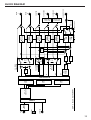
19
BLOCK DIAGRAM
AC-3
DECODER
SMALL
HPF
B4.
LFE MIX
LEVEL
-4.5dB
+10dB
-4.5dB
AC-3
RF
OPTICAL
COAXIAL
DEMO-
DULATOR
LARGE
PHANTOM
LARGE
SMALL
LARGE
SMALL
HPF
HPF
-3dB
-4.5dB
HPF
HPF
HPF
LPF
4th
order
LPF
4th
order
2nd order
2nd order
2nd order
2nd order
2nd order
20bit
D/A
C4. MAIN
SPEAKERS
C2. CENTER
SPEAKER
C3. REAR
SPEAKERS
C5. LFE/BASS OUT
20bit
D/A
CROSSOVER 90Hz
MAIN
L
MAIN
R
CENTER
SURROUND
L
SURROUND
R
DDP-1
BLOCK DIAGRAM
SUBWOOFER
RS
LFE
LS
C
L
R
SUBWOOFER
MAIN
20bit
D/A
C1. INPUT
B5. OUTPUT TRIM
B2. LEFT
SUR LEVEL
B3. RIGHT
SUR LEVEL

YAMAHA ELECTRONICS CORPORATION, USA 6660 ORANGETHORPE AVE., BUENA PARK, CALIF. 90620, U.S.A.
YAMAHA CANADA MUSIC LTD. 135 MILNER AVE., SCARBOROUGH, ONTARIO M1S 3R1, CANADA
YAMAHA ELECTRONIK EUROPA G.m.b.H. SIEMENSSTR. 22-34, 25462 RELLINGEN BEI HAMBURG, F.R. OF GERMANY
YAMAHA ELECTRONIQUE FRANCE S.A. RUE AMBROISE CROIZAT BP70 CROISSY-BEAUBOURG 77312 MARNE-LA-VALLEE CEDEX02, FRANCE
YAMAHA ELECTRONICS (UK) LTD. YAMAHA HOUSE, 200 RICKMANSWORTH ROAD WATFORD, HERTS WD1 7JS, ENGLAND
YAMAHA SCANDINAVIA A.B. J A WETTERGRENS GATA 1, BOX 30053, 400 43 VÄSTRA FRÖLUNDA, SWEDEN
YAMAHA MUSIC AUSTRALIA PTY, LTD. 17-33 MARKET ST., SOUTH MELBOURNE, 3205 VIC., AUSTRALIA
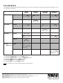
FOR REFERENCE
The following table shows what terminal(s) the signals of each channel are output to according to the output mode settings on C2 to
C5. (See page 10 for details.)
*
1 : When C5. LFE/BASS OUT is set at the MAIN position
*
2 : When C5. LFE/BASS OUT is set at the SUBWOOFER position
*
3 : When C2. CENTER is set at the SMALL position
*
4 : When C3. REAR is set at the SMALL position
*
5 : When C4. MAIN is set at the SMALL position
: The shaded areas show the original settings and output modes.
C2. CENTER
C3. REAR
C4. MAIN
C5. LFE
/BASS OUT
SMALL
LARGE
SMALL
LARGE
SMALL
LARGE
MAIN
SUBWOOFER
MAIN
OUTPUT
CENTER
OUTPUT
SURROUND
OUTPUT
SUBWOOFER
OUTPUT
90 Hz or more*
2
90 Hz or more
90 Hz or more
90 Hz or less *
2
90 Hz or less *
2
90 Hz or less *
1
90 Hz or less *
1
90 Hz or less (from
MAIN, CENTER
*
3
and REAR
*
4
)
90 Hz or less *
2
FULL *
1
FULL
FULL
FULL
LFE
90 Hz or less (from
MAIN
*
5
, CENTER
*
3
and REAR
*
4
)
LFE
VT89040 Printed in Japan
-
 1
1
-
 2
2
-
 3
3
-
 4
4
-
 5
5
-
 6
6
-
 7
7
-
 8
8
-
 9
9
-
 10
10
-
 11
11
-
 12
12
-
 13
13
-
 14
14
-
 15
15
-
 16
16
-
 17
17
-
 18
18
-
 19
19
-
 20
20


Yamaha 1 Bedienungsanleitung
- Kategorie
- Empfänger
- Typ
- Bedienungsanleitung
- Dieses Handbuch eignet sich auch für
in anderen Sprachen
- English: Yamaha 1 Owner's manual
- français: Yamaha 1 Le manuel du propriétaire
- español: Yamaha 1 El manual del propietario
- italiano: Yamaha 1 Manuale del proprietario
- русский: Yamaha 1 Инструкция по применению
- Nederlands: Yamaha 1 de handleiding
- português: Yamaha 1 Manual do proprietário
- dansk: Yamaha 1 Brugervejledning
- polski: Yamaha 1 Instrukcja obsługi
- čeština: Yamaha 1 Návod k obsluze
- svenska: Yamaha 1 Bruksanvisning
- Türkçe: Yamaha 1 El kitabı
- suomi: Yamaha 1 Omistajan opas
- română: Yamaha 1 Manualul proprietarului
Verwandte Artikel
-
Yamaha DDP-2 Bedienungsanleitung
-
-
-
-
Yamaha DSP-A1 Benutzerhandbuch
-
-
-
-
Yamaha DSP-AZ2 Benutzerhandbuch
-